 Open Access Article
Creative Commons Attribution 3.0 Unported Licence
Quenching-assisted actuation mechanisms in core–shell structured BiFeO3–BaTiO3 piezoceramics†
Ilkan
Calisir
 a,
Annette K.
Kleppe
 b,
Antonio
Feteira
 c and
David A.
Hall
 *a
*a
aSchool of Materials, University of Manchester, M13 9PL, Manchester, UK. E-mail: david.a.hall@manchester.ac.uk
bDiamond Light Source Ltd, Harwell Science and Innovation Campus, OX11 0DE, Didcot, UK
cDepartment of Engineering and Maths, Sheffield Hallam University, S1 1WB, Sheffield, UK
First published on 29th July 2019
Abstract
Electromechanical actuation in piezoceramics is usually enhanced by creating chemically homogeneous materials with structurally heterogeneous morphotropic phase boundaries, leading to abrupt changes in ion displacement directions within the perovskite unit cell. In the present study, an alternative mechanism to enhance electromechanical coupling is found in both chemically and structurally heterogeneous BiFeO3–BaTiO3 lead-free piezoceramics. Such a mechanism is observed in a composition exhibiting core–shell type microstructure, associated with donor-type substitution of Ti4+ for Fe3+, and is primarily activated by thermal quenching treatment. Here, we describe the use of in situ high-energy synchrotron X-ray powder diffraction upon the application of a high electric field to directly monitor the ferroelectric and elastic interactions between these composite-like components, formed as core and shell regions within grains. Translational short or long-range ordering is observed in the BiFeO3-depleted shell regions which undergo significant structural alterations from pseudocubic Pm![[3 with combining macron]](https://www.rsc.org/images/entities/char_0033_0304.gif) m relaxor-ferroelectric in slow-cooled ceramics to rhombohedral R3c or R3m with long-range ferroelectric order in the quenched state. The strain contributions from each component are calculated, leading to the conclusion that the total macroscopic strain arises predominantly from the transformed shell after quenching. Such observations are also complemented by investigations of microstructure and electrical properties, including ferroelectric behaviour and temperature-dependent dielectric properties.
m relaxor-ferroelectric in slow-cooled ceramics to rhombohedral R3c or R3m with long-range ferroelectric order in the quenched state. The strain contributions from each component are calculated, leading to the conclusion that the total macroscopic strain arises predominantly from the transformed shell after quenching. Such observations are also complemented by investigations of microstructure and electrical properties, including ferroelectric behaviour and temperature-dependent dielectric properties.
1. Introduction
Electromechanical coupling is a characteristic feature of piezoceramics attained through large ion displacements, which are generated in the unit cell, yielding observable mechanical strain in response to an applied electric field and vice versa. This coupling allows piezoceramics to be used as electroactive materials in a number of applications requiring mechanical actuation (actuators), acoustic and resonance (transducers and ultrasonics) and sensing (sensors).1,2 To achieve high electromechanical sensitivity and piezoelectric coefficients in piezoceramics, there has been a tremendous effort to understand the origin of the high piezoelectric response in both lead-based and lead-free ceramics. Most investigations on the search for lead-free replacements (arising due to the worldwide legislation to reduce the use of hazardous substances such as lead-based oxides including all sectors),3 aim to achieve at least an equivalent performance to that of lead-based compounds. The search has been mainly focused on identifying the region or boundary, known as the morphotropic phase boundary (MPB), where associated piezoelectric activities are optimised in a solid solution, including piezoelectric coefficient d33, electrostrain x33, relative permittivity εr and electromechanical coupling coefficient kp, for example. Exhaustive compositional studies on the promising lead-free ceramics including sodium-bismuth-titanate (NBT)-, potassium sodium niobate (KNN)-, barium calcium zirconate titanate (BCZT)- and bismuth ferrite (BF)-based solid solutions have revealed the occurrence of such regions in those solid solutions, though the reported properties are often insufficient for use as a replacement for lead-based compounds.Nevertheless, new findings and approaches are still being reported and intriguing properties demonstrated. Such investigations exploit the high flexibility of the perovskite structure, doping strategies, abundance of oxides and their combinations, and composition- or temperature-dependent phase transformations. Reported novel phenomena such as presence/role of incommensurate phases within multiphase coexistence region/boundary/points, ergodicity in relaxor ferroelectrics and microstructure design approaches undoubtedly provide an alternative perspective on finding a green and multifunctional material.
BiFeO3 (BF) is regarded as a special multiferroic compound and has attracted great attention as a room temperature multiferroic.4 Its solid solutions with other ABO3-type perovskite end-members have recently been of great interest amongst ferro-piezoelectric polar dielectric materials, particularly after the issues associated with inherent high leakage current4 and phase decomposition5 were addressed successfully via doping6–8 and synthesis strategies.9 Particular attention can be drawn to BiFeO3–BaTiO3 (BF–BT) solid solutions, which have been intensively studied as promising candidates for high temperature piezoceramic applications,8,10,11 surpassing the temperature capability of typical lead-based ferroelectrics. To date, the highest d33 in xBF–BT ceramics was reported as 402 pC N−1, with a small amount of BiGaO3 being incorporated in the composition with x = 0.67; these ceramics were prepared by water-quenching and were assumed to have an MPB composition, with coexistence of rhombohedral and tetragonal phases.10 However, this report still remains as the only one showing such a high d33 and claiming the presence of a rhombohedral and tetragonal phase boundary in a BF–BT-based solid solution.
Intriguingly, the influence of quenching treatment regardless of the factors such as cooling methods10,12 (e.g. liquid nitrogen, water, air, NaCl solution) and type of dopants,10,13,14 is readily accepted as an effective means to modify the piezo-ferroelectric performance in BF-based ceramics, including pristine BiFeO3.9 However, the underlying mechanism is yet to be understood fully and is under debate.7,13,15,16 On the other hand, in conventional type ferroelectrics such as acceptor-doped hard PZT and BT-based ferroelectrics, the quenching-induced enhancement in polarisation switching behaviour is mainly attributed to the randomization of dipolar defect associates, which generally become oriented along the local domain polarisation direction during an extended ageing period at room temperature and thereby act to constrain domain wall motion.17
The present work aims to shed light on the origin of enhancement in the electromechanical coupling as a result of thermal quenching treatments in BF–BT solid solutions. A fine compositional adjustment involving the incorporation of 1 mol% Ti4+ as a donor substitution for Fe3+ has been applied to the selected composition. Donor dopants play a key role in soft PZT ceramics, improving insulation resistance, enhancing domain wall mobility and hence increasing the piezoelectric performance.18 In contrast, for BF–BT ceramics we have recently demonstrated that donor-doping with La3+ substituted for Ba2+ resulted in a unique core–shell type microstructure as a result of chemical phase segregation on the micro- and nano-scale, leading to significant degradation in polarisation switching.6 Moreover, the application of quenching significantly altered the crystal structure in the shell regions, accompanied by a dramatic enhancement in polarisation.
In the present study, the effect of quenching on the actuation mechanisms in core–shell structured BF–BT composition and its influence on the phase assemblages have been revealed by using in situ high-energy synchrotron diffraction techniques. The results of these investigations provide an unprecedented insight into the understanding of this novel actuation mechanism, thereby providing a route to tailor the electromechanical responses of newly-designed piezoceramics in future.
2. Results and discussion
Ti-substituted BF–BT ceramics were synthesised by the solid state reaction method, based on the chemical formula of 0.75Bi(Fe1−xTix)O3–0.25BaTiO3 with x = 0.01, 0.03 and 0.05. Sintered ceramics were annealed at 800 °C for 20 min and then divided into two groups based on the cooling procedure employed, which was either (a) a slow cooling rate of 300 °C h−1 or (b) air-quenching to room temperature. The ceramic samples resulting from these procedures are hereafter denoted as either slow-cooled and quenched. Further details of the processing and characterisation methods are provided in the ESI.†2.1 Phase content and microstructure
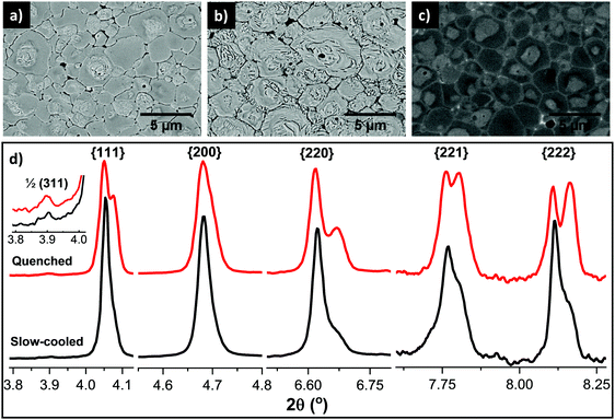
Micrographs and X-ray diffraction patterns of 1 mol% Ti substituted-0.75BiFeO3–0.25BaTiO3 (BF–BT–1Ti) ceramics, for both slow-cooled and quenched states are presented in Fig. 1. Microstructural examination of the chemically-etched polished surfaces of the sintered ceramics is also shown in Fig. 1(a) and (b), respectively. The appearance of ferroelectric-type domain structures can be clearly observed for both slow-cooled and quenched states. However, the domain features are mainly concentrated in the central regions of the grains after slow cooling, while quenching led to additional domain features between the grain boundaries and the centres of the grains. Such features led us to investigate the polished surfaces without the application of etching; the occurrence of chemical heterogeneity was qualitatively confirmed using SEM in back-scattered electron (BSE) mode at high energy, as shown Fig. 1(c). It is apparent that the grain boundaries and most grain centres consist of heavier elements giving lighter contrast under BSE mode, indicating that those regions are bismuth-rich, while the darker regions are lacking in bismuth, which is the heaviest element relative to Fe, Ba and Ti.Since the solid solution is primarily composed of two perovskite phases, with end members BiFeO3 and BaTiO3, the observed regional contrast could be due to phase separation of these two components as a result of both thermodynamic and kinetic factors. This issue has been discussed in detail in our previous investigations of BiFeO3–BaTiO3 ceramics.7 It is also noted that minor amounts of impurities were detected, which appeared as the brightest contrast and could indicate the presence of expelled or excess bismuth oxide. The segregated phases, determined as BiFeO3-rich and -depleted regions, will hereinafter be referred to as core and shell regions, respectively. These results provide microstructural evidence of chemical heterogeneity at the micro-scale and will be used as the basis of discussions in the following sections. Note that although 1 mol% Ti-doped ceramics are the main focus of the present study, further systematic studies were also carried out, including doping levels up to 5 mol% Ti. The micrographs given in the ESI† (Fig. S1), show that highly uniform and homogeneous grain-domain types were obtained for the undoped composition, while further doping of Ti (>1 mol%) in BF–BT–Ti composition results in increased amounts of Bi-rich secondary phases, together with a reduced volume fraction of core regions.
The aforementioned chemical and domain heterogeneity within grains was also qualitatively confirmed using high-energy X-ray diffraction, as illustrated by the detailed peak profiles of particular crystallographic orientations for {111}, {200}, {220} and {222} shown in Fig. 1(d). The slow-cooled samples show a pseudocubic structure, which is discernible by the absence of preferred orientation, namely lack of splitting of the {111} and {200} peaks. However weak additional peaks were evident along with the main pseudocubic reflections at higher scattering angles, corresponding to {220}, {221} and {222} reflections, thereby suggesting a coexistence of multiple phases. Furthermore, the application of quenching caused pronounced peak splitting of {111} and significant broadening of {200} peaks. This observation strongly suggests that the crystal structure, which is multiphase due to the formation of the core–shell microstructure, undergoes significant transformations upon quenching.
Of particular note is a weak peak at 2θ ≈ 3.9° in Fig. 1(d), representing the super-lattice peak, which is indexed as 1/2(311) with respect to the pseudocubic unit cell. It is visible in the diffraction patterns obtained from both ceramics. This superlattice reflection corresponds to the a−a−a− tilt system in the space group R3c in Glazer's notation.19 It is due to oxygen planes caused by antiferrodistortive rotation of oxygen octahedra with an antiphase tilt in relation to the neighbouring octahedra,5 and thus it has a low intensity due to the weak interactions between X-rays and light ions such as oxygen. Since the microstructural evidence suggests that the core is present in both cases without any prominent changes, in comparison with those in the transformed shell, it is concluded that the observed superlattice peak in both patterns corresponds to the common phase of the BiFeO3-rich core.
2.2 Structural analysis
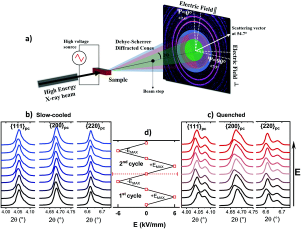
In the light of these observations, full-pattern refinement was performed to identify the crystal structures of the phases present. The high-energy X-ray diffraction patterns for the in situ study were recorded on the panel detector, yielding 2D Debye–Scherrer diffraction rings that provide an insight into the full range of grain orientations as a function of crystallographic orientation (Fig. 4(a)). However, among these rings there is one specific orientation angle, satisfying the relation cos2![[thin space (1/6-em)]](https://www.rsc.org/images/entities/char_2009.gif) ψ = 1/3,
ψ = 1/3,  , which can be used for full-pattern structural refinement even after poling under a high electric field.20 At this orientation, the domains are randomly oriented and therefore crystallographic texture is almost negligible. Furthermore, the elastic lattice strains associated with the development of inter-granular stresses are close to zero at this orientation, which facilitates the refinement of crystal structure and calculation of phase fractions without the need to incorporate models for the domain and strain orientation distribution functions (DOD and SOD, respectively).
After the determination of the specific orientation angle required for the full pattern refinement, the structural model was first constructed based on rhombohedral symmetry with R3c space group, which is the well-known crystal structure of BiFeO3.4,5,9 However, it was found that the single phase model could not resolve the structure properly and therefore another crystal symmetry, pseudocubic Pm![[3 with combining macron]](https://www.rsc.org/images/entities/char_0033_0304.gif) m, which is commonly assigned for xBF–BT ceramics (x < 75%),21–24 was added into the model. The refinement was significantly improved. However, the R3c + Pm
m, which is commonly assigned for xBF–BT ceramics (x < 75%),21–24 was added into the model. The refinement was significantly improved. However, the R3c + Pm![[3 with combining macron]](https://www.rsc.org/images/entities/char_0033_0304.gif) m model is only reasonable for the slow-cooled state since the R3c phase corresponds to the ferroelectric core, while the featureless shell could comprise the non-polar Pm
m model is only reasonable for the slow-cooled state since the R3c phase corresponds to the ferroelectric core, while the featureless shell could comprise the non-polar Pm![[3 with combining macron]](https://www.rsc.org/images/entities/char_0033_0304.gif) m phase. On the other hand, it is not appropriate for the quenched state since the appearance of ferroelectric domains in the shell appears to indicate the transformation from non-polar or relaxor Pm
m phase. On the other hand, it is not appropriate for the quenched state since the appearance of ferroelectric domains in the shell appears to indicate the transformation from non-polar or relaxor Pm![[3 with combining macron]](https://www.rsc.org/images/entities/char_0033_0304.gif) m to a polar ferroelectric R3c configuration. To simplify the model for both states, a new binary model was designated as comprising R3cCore and R3cShell phases, which serves to represent the core and shell regions in both the slow-cooled and quenched states, as illustrated in Fig. 2(a) and (b). According to this simplified approach, the pseudocubic phase can be represented by a rhombohedral structure with near-zero rhombohedral distortion.
m to a polar ferroelectric R3c configuration. To simplify the model for both states, a new binary model was designated as comprising R3cCore and R3cShell phases, which serves to represent the core and shell regions in both the slow-cooled and quenched states, as illustrated in Fig. 2(a) and (b). According to this simplified approach, the pseudocubic phase can be represented by a rhombohedral structure with near-zero rhombohedral distortion.
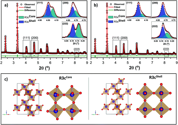 | ||
| Fig. 2 Full-pattern structure refinement of (a) quenched and (b) slow-cooled BF–BT–1Ti ceramics. (c) (Fe/Ti)O6 octahedral illustrations of core and shell structures in the quenched state. | ||
The structural parameters obtained from the refinement are summarised in Table S1 (see the ESI†). It is evident that the R3c phase fractions of the core and shell regions changed significantly as a result of the quenching process, although deviations in the unit cell parameters were minimal. Although R3c crystal symmetry is used in the hexagonal setting for the refinement, it is more convenient to convert the hexagonal lattice parameters (ah and ch) into the pseudocubic setting, calculated as below:
 | (1) |
Another important parameter in structural analysis is the lattice distortion and associated inter-axial angles. The rhombohedral lattice distortion, ηrh can be calculated by eqn (2)25 while the relation between the lattice inter-axial angles for rhombohedral, αrh, and pseudocubic, αpc, is given in eqn (3).26
 | (2) |
 | (3) |
To demonstrate the differences between the core and shell structures sharing R3c symmetry in the quenched state, a crystallographic information file (CIF) was generated from the refinement and illustrated in Fig. 2(c). It is evident that the distortions of the (Fe/Ti)O6 octahedra are clearly distinguished between the core and shell structures. The Fe–O–Fe angle for BiFeO3 itself is reported as 154.1°.27 Therefore, it can be deduced that the regions with high BiFeO3 phase content are responsible for the observed large distortions in the octahedra, yielding a B–O–B angle of 157.4°, for the quenched state, commensurate with the occurrence of a−a−a− tilt. On the other hand, suppression of octahedral tilting and a slight deviation in the B–O–B angle of the shell could be an indication of untilted R3c, namely R3m, as similarly observed in 0.75Bi(Fe2/8Mg3/8Ti3/8)O3–0.25BaTiO3 reported by Dolgos et al.28 The origin of such contrasting character could be due to large differences in ionic radii of the A-site ions (rBa = 1.61 Å and rBi = 1.45 Å) since the shell phase is BiFeO3-depleted. This confirms the correlation between tilting and cation size of A-site ions as reported by Megaw,26 suggesting that reduction in the radii of the A-cations in relation to octahedron edge length, l ((rA + rOxygen)/l) causes the suppression of octahedral tilting.
2.3 Dielectric and ferroelectric properties
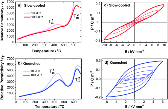
The results presented in Fig. 3 illustrate the εr–T and P–E relationships for the slow-cooled and quenched BF–BT ceramics. In the former case, a lower-temperature dielectric anomaly is evident in the vicinity of T1m ≈ 400 °C; whilst with further heating another dielectric maximum is apparent at a higher temperature T2m ≈ 625 °C for both slow-cooled and quenched states. However, a dramatic increase in the magnitude of εr near T1m was observed in the quenched ceramic, but the magnitude was relatively suppressed and diffuse with a marked frequency-dependence for the slow-cooled ceramic. Such changes in the magnitude of εr can be understood on the basis of the increase in intrinsic polarizability near the phase transition temperatures, while the frequency dispersion is a typical signature of relaxor ferroelectric behaviour. In common with our previous publications,6,7 we attributed the transitions at T1m and T2m to contribution from the shell and core regions, respectively.Variations in dielectric loss, tan![[thin space (1/6-em)]](https://www.rsc.org/images/entities/char_2009.gif) δ, as a function of temperature and frequency for slow-cooled and quenched ceramics are shown in Fig. S3 (ESI†). Multiple anomalies in the dielectric permittivity are clearly observed in the cases of slow-cooled and quenched ceramics (Fig. 3a and b), whereas there is only one loss peak in the region of the Curie point, at a temperature of 575 °C, becoming more pronounced for the quenched case. This may be due to increased ferroelectric domain wall density after the quenching operation, which accordingly leads to higher dielectric loss near the Curie temperature. It is also observed that dielectric loss increases rapidly above 400 °C due to high electrical conductivity, as commonly reported in BiFeO3-based ceramics.7–11 Dielectric loss responses in the core and shell regions are masked by the observed high conductivity and thus cannot be easily distinguished.
δ, as a function of temperature and frequency for slow-cooled and quenched ceramics are shown in Fig. S3 (ESI†). Multiple anomalies in the dielectric permittivity are clearly observed in the cases of slow-cooled and quenched ceramics (Fig. 3a and b), whereas there is only one loss peak in the region of the Curie point, at a temperature of 575 °C, becoming more pronounced for the quenched case. This may be due to increased ferroelectric domain wall density after the quenching operation, which accordingly leads to higher dielectric loss near the Curie temperature. It is also observed that dielectric loss increases rapidly above 400 °C due to high electrical conductivity, as commonly reported in BiFeO3-based ceramics.7–11 Dielectric loss responses in the core and shell regions are masked by the observed high conductivity and thus cannot be easily distinguished.
Ferroelectric P–E hysteresis loops for the slow-cooled and quenched ceramics are shown in parts (c) and (d) of Fig. 3, respectively. For the slow-cooled state, constricted P–E loops were obtained under AC electric fields with magnitude up to 10 kV mm−1. This constrained switching behaviour is attributed to the presence of polar nanodomains, commonly found in relaxor ferroelectric phases, indicating that oriented ferroelectric domains developed under high electric fields are unstable and cannot be retained after the removal of the field. It is evident that at a moderate electric field (E = 5 kV mm−1), an almost linear response was recorded. According to the common interpretation given in the literature for such cases, it is linked to the transformation of randomly oriented polar nano regions (PNRs) to ordered ferroelectric domains, leading to the observed increase in polarization, while upon removal of the electric field the developed domains are dispersed into discrete PNRs, thus leading to almost zero net polarization at zero field.29 Nevertheless, upon further increasing the field to 10 kV mm−1, the loop transformed into a more open shape around the tip, although the polarisation was not retained on removal of the field. Similar behaviour has been observed previously in acceptor-doped normal ferroelectrics, although in that case it is generally attributed to domain wall pinning effects rather than the presence of PNRs.30 On the other hand, for the quenched case, a nonlinear and strongly hysteretic P–E response was developed even at a field of 3 kV mm−1, and a near-saturated loop was obtained at 6 kV mm−1.
Temperature-dependent ferroelectric P–E hysteresis loops for both slow-cooled and quenched ceramics were measured at 6 kV mm−1 up to 150 °C, as illustrated in Fig. S2 (ESI†). Ferroelectric domain switching or domain wall movement in conventional ferroelectric-type ceramics can be enhanced by increasing temperature, resulting in reduced coercive field and higher switched polarisation values, as seen for the quenched case. Nonetheless, for the slow-cooled case, a gradual increase in polarisation and relatively larger increase at EMax = 6 kV mm−1, is observed. However, a constricted appearance of the P–E hysteresis loop was maintained. At a temperature of 150 °C, rounded hysteresis loops were observed for both the slow-cooled and quenched states, indicating increased leakage current due to thermally-activated conductivity.
It is known that the nucleation and growth of ferroelectric domains, together with their subsequent mobility, greatly impacts upon the macroscopic polarisation switching behaviour. It is speculated that grain boundaries act as pinning centres for the ferroelectric domains, thereby generally restricting the domain wall motion, which in turn reduces the magnitude of bulk polarization changes during external stimuli.31 Based on this view, the absence of domain features in the shell regions of the slow-cooled ceramic could be used as a strong argument that the featureless shell can be treated as an intra-grain boundary that acts to restrain domain switching in the ferroelectric core, for electric field levels exceeding its coercive field. On the other hand, the observation of micro-sized ferroelectric domains in the shell region of the quenched ceramic indicates that the restrictive intra-granular elastic constraint was diminished and an environment for effective domain wall mobility was created. Therefore, it can be concluded that the observed heterogeneous microstructure gives rise to heterogeneous polarisation switching mechanisms. In such a case, there is no need to invoke any defect-related pinning mechanisms to explain the constrained polarisation switching behaviour of the slow-cooled ceramic.
2.4 In situ investigation of microscopic actuation mechanisms
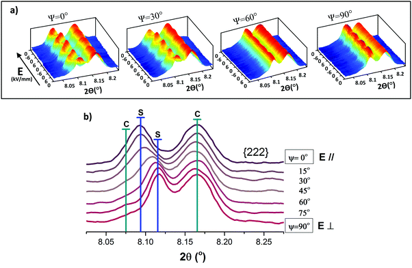
A polycrystalline ferroelectric ceramic subjected to an applied electric field will give rise to a unique diffraction pattern on the detector for each grain orientation, ψ, relative to the applied field direction, as illustrated schematically in Fig. 4(a). For example, the relative intensities of the hhh-type diffraction peaks in rhombohedral symmetry change due to the electric field-induced changes in crystallographic texture (i.e. preferred orientation of the non-180° ferroelectric domain structure), whereas peak shifts occur in h00-type peaks due to variations in the lattice spacing.20,32 To monitor and quantify the contribution of such changes relative to the total electrostrain, it is necessary to determine the extrinsic and intrinsic contributions associated with domain switching and lattice strain, respectively.20,32–34 Thus, certain crystallographic orientations such as {111}, {200} and {220} will be examined in order to make an initial assessment of the microscopic actuation mechanisms.Diffraction patterns corresponding to ψ = 0° (i.e. representing grain families oriented with their scattering vectors parallel to the electric field) for the slow-cooled and quenched ceramics are shown in Fig. 4(b) and (c), respectively. These patterns correspond to the points where the electric field varies from 0 to ±6 kV mm−1 (±EMAX), yielding 2 bipolar cycles in the triangular waveform, as illustrated in Fig. 4(d). It is evident that on increasing the electric field, the structural variations in the slow-cooled state were minimal and only a slight peak broadening was observed at ±EMAX. In contrast, the influence of the applied electric field on the peak profiles of {111}, {200} and {220} for the quenched ceramic was substantial, particularly at ±EMAX. After the removal of the field, peak splitting for {111} and {220} was more pronounced and a noticeable peak broadening was also observed for {200}. Qualitatively, these observations indicate that the electromechanical response in the slow-cooled state is minimal and cannot be assessed readily due to the presence of asymmetric peak broadening and lack of noticeable features. However, the pronounced variations in the {111}, {200} and {220} peak profiles for the quenched state show clear evidence of the ferroelectric domain switching phenomena and electric field-induced strain.
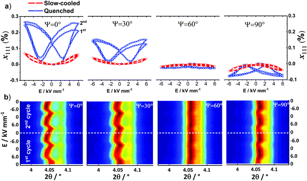
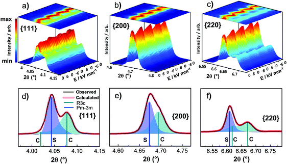
To quantify the microscopic strain for the slow-cooled and quenched ceramics, the {111} peak profile, which is the characteristic polar direction for rhombohedral symmetry, was de-convoluted into two peaks using a pseudo-Voigt function within Matlab. The effective average lattice strain associated with this grain orientation, x111ψ, was estimated on the basis of a simple weighted average of the diffraction peak positions. This operation was performed on particular grain orientations, with ψ = 0°, 30°, 60° and 90° (Fig. 5(a)). It was found that the variations in the strain, x111 as a function of grain orientation are consistent with the response of a typical rhombohedral ferroelectric.20 The largest positive strain was observed at ψ = 0°, for the quenched state, indicating development of tensile strain along the field direction; this was reduced in magnitude at 30° and diminished almost to zero at 60°, which is expected to be near the texture-free orientation of 54.7°. Subsequently, negative strains were observed at 90° due to development of compressive strain along the transverse direction. It is also evident that the application of the 2nd bipolar cycle to the quenched ceramic enhanced the symmetric shape of the loop. This observation indicates that re-orientation of domains under an electric field was stabilised with subsequent cycling, which in turn led to a symmetric loop as a result of improved poling. On the other hand, by inspection of the surface contour plots for {111} given in Fig. 5(b), it appears that the characteristic preferred orientation in the (111) and (![[1 with combining macron]](https://www.rsc.org/images/entities/char_0031_0304.gif) 11) doublet, which is normally expected for domain switching in a typical rhombohedral ferroelectric, is absent.20,32 Instead, there was a combination of large peak shift starting from 2θ ≈ 4.06° and slight intensity fluctuations in the peak at 2θ ≈ 4.09°.
11) doublet, which is normally expected for domain switching in a typical rhombohedral ferroelectric, is absent.20,32 Instead, there was a combination of large peak shift starting from 2θ ≈ 4.06° and slight intensity fluctuations in the peak at 2θ ≈ 4.09°.
To seek a further indication of domain switching, the variations in the peak profile of the {222} reflection as a function of grain orientation were also examined, as shown in Fig. 6, for the quenched state. Similar to the behaviour of the {111} diffraction peak under the electric field, variations in the {222} peak profiles are predominantly composed of peak shifts and intensity fluctuations, which differ with grain orientation angle, ψ. However, from the diffraction profile of {222} in the remanent state (after the 1st cycle) plotted as a function of grain orientation (Fig. 6(b)), it can be seen that systematic intensity variations and hence preferred domain orientation can be identified with the assistance of the previous structural refinement presented in Fig. 2(a).
If we take the scattering angles corresponding to R3cCore and R3cShell of {222} from the full-pattern refinement and position them on the plot, denoted as C and S, respectively (Fig. 6(b)), there is a close match with the observed large peak shift, indicating that it could be indeed a consequence of domain switching within the shell component. Since the rhombohedral distortion in the shell is not as large as that in the core, the individual peaks are not resolved and we observe significant peak shifts instead of the typical texturing in rhombohedral R3c symmetry.20,32 This introduces a complication in that the intrinsic and extrinsic contributions of the shell phase cannot be readily distinguished and therefore, for the following strain analysis, it is treated as an effective average lattice strain, which is a sum of the intrinsic and extrinsic contributions. On this basis, the strain contributions from the core and shell regions are quantified in the following section.
The detailed fitting procedure employed the following steps:
(i) The {111}, {200} and {220} crystallographic orientations were evaluated to provide a representative weighted average, enabling an estimation of the total macroscopic strain of the polycrystal.35 Full pattern fitting of the diffraction patterns obtained under an applied electric field was not considered to be appropriate due to elastic interactions between differently-oriented grains together with anisotropy of elastic and piezoelectric properties, which are not currently accounted for within standard diffraction software.
(ii) An initial attempt was made to fit the individual diffraction peak profiles with R3cCore and R3cShell phases, as suggested by the structural refinement in Fig. 2(a). However, it was challenging to extract the individual intensities of the (111) and (![[1 with combining macron]](https://www.rsc.org/images/entities/char_0031_0304.gif) 11) peaks for the fitted shell phase, due to a combination of peak broadening and the limited resolution of the detector. This problem is exacerbated since the rhombohedral lattice distortion in the shell (ηrh = 0.18%) was relatively small in comparison with that of the core (ηrh = 1.2%), as given in Table S1 (see the ESI†). Therefore, the crystal structure of the shell phase was approximated as pseudocubic Pm
11) peaks for the fitted shell phase, due to a combination of peak broadening and the limited resolution of the detector. This problem is exacerbated since the rhombohedral lattice distortion in the shell (ηrh = 0.18%) was relatively small in comparison with that of the core (ηrh = 1.2%), as given in Table S1 (see the ESI†). Therefore, the crystal structure of the shell phase was approximated as pseudocubic Pm![[3 with combining macron]](https://www.rsc.org/images/entities/char_0033_0304.gif) m.
m.
(iii) Asymmetric and broad peaks were fitted by de-convoluting into three peaks for {111} and {220}, and two peaks for {200}. The modified Pseudo-Voigt function (PV-TCHZ) was used to extract the information from which the structural parameters of the associated core and the shell phases (e.g. magnitude of integrated intensity, inter-planar lattice spacing, structure factors) were determined.
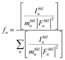
Based on the fitting procedure described above, the crystal structure is now considered to comprise a combination of R3cCore and Pm![[3 with combining macron]](https://www.rsc.org/images/entities/char_0033_0304.gif) mShell phases. Each phase fraction, fn can be then determined by
mShell phases. Each phase fraction, fn can be then determined by
 | (4) |
![[1 with combining macron]](https://www.rsc.org/images/entities/char_0031_0304.gif) 11) domain orientations of the core respectively, and calculated accordingly using eqn (4).
11) domain orientations of the core respectively, and calculated accordingly using eqn (4).
The structure factors for each hkl were obtained from the full-pattern structure refinement of the unpoled (randomly-oriented) ceramic. During this peak fitting analysis, the phase fraction of Pm![[3 with combining macron]](https://www.rsc.org/images/entities/char_0033_0304.gif) mShell was found to be around 60% and it was invariant under the electric field variation, for ψ = 0°. Therefore, the electric field-induced phase transformation was disregarded in the following strain calculations.
mShell was found to be around 60% and it was invariant under the electric field variation, for ψ = 0°. Therefore, the electric field-induced phase transformation was disregarded in the following strain calculations.
Subsequently, the average effective d-spacing at zero electric field,  , and under the electric field dhkltotal can be expressed in relation to the corresponding phase fractions obtained from eqn (4),
  and fhkln, as follows:
 | (5) |
 | (6) |
 | (7) |
It should be noted that overlapping of the selected diffraction peaks corresponding to core and shell phases as observed in Fig. 7(d) and (f) may cause relatively large uncertainties and deviations in the individual contribution to the strain profiles. Thus, a further modification is required for reliable strain determination, as described in the following section.
The macroscopic strain was estimated based on the weighted average of the effective lattice strains associated with different crystallographic orientations, according to the equation shown below32,36
 | (8) |
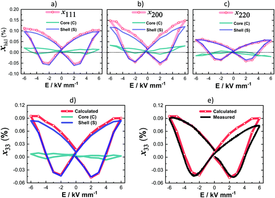
The total longitudinal strain, x33, was calculated in terms of a volume weighted average of the different effective lattice strains, xhkl, measured parallel to the applied electric field direction, ψ = 0°. The calculated results are illustrated in Fig. 8(d), comparing each contribution of core and shell phases as well as the net macroscopic strain. It is evident that the macroscopic strain obtained from the shell is predominant, while the core contribution is almost negligible, indicating that the observed large electromechanical actuation is a result of mainly one component in the electric field range up to 6 kV mm−1. These results are consistent with the presence of a BiFeO3-rich core having a coercive field significantly higher than those accessed during the present study.
On the other hand, strain anisotropy and elastic coupling parameters must also be taken into account when analysing heterogeneous-type actuation mechanisms associated with a grain and its surroundings. The cyclic variations in lattice strain for {111}, {200} and {220} as a function of frame number along the electric field direction, ψ = 0°, are shown in Fig. S4a (ESI†). It can be seen that the largest strain contribution was from {200} grain families, which tends to contradict the expected dominance of the polar 〈111〉 directions for materials exhibiting rhombohedral crystal structure. It should be noted that although the shell phase has been refined as rhombohedral structure with reduced rhombohedral lattice distortion and octahedral tilting, it was characterised as Pm![[3 with combining macron]](https://www.rsc.org/images/entities/char_0033_0304.gif) m during peak profile fitting due to the relatively low resolution. Although strain anisotropy in the grain families of {111}, {200} and {220} is apparent, normalisation of x111, x200 and x220 depicted in Fig. S4b (ESI†) shows that the cyclic strains induced by the electric field in these grain families are strongly correlated due to elastic coupling between grains having different crystallographic orientations. It has been reported recently that in structurally heterogeneous regions such as near phase boundaries in BiFeO3-based ceramics, field-induced phase transformation dynamics and rates are particularly important to obtain high electromechanical response.37,38 However, there is no evidence of any such electric field-induced phase transformations in the present results.
m during peak profile fitting due to the relatively low resolution. Although strain anisotropy in the grain families of {111}, {200} and {220} is apparent, normalisation of x111, x200 and x220 depicted in Fig. S4b (ESI†) shows that the cyclic strains induced by the electric field in these grain families are strongly correlated due to elastic coupling between grains having different crystallographic orientations. It has been reported recently that in structurally heterogeneous regions such as near phase boundaries in BiFeO3-based ceramics, field-induced phase transformation dynamics and rates are particularly important to obtain high electromechanical response.37,38 However, there is no evidence of any such electric field-induced phase transformations in the present results.
The accuracy of the calculated total strain is evaluated in Fig. 8(e) by comparison with the macroscopic strain–electric field data, measured on a different test specimen using an AixACCT TF 2000 system. It is apparent that the calculated S–E loop is highly symmetric with a good match on the negative side of electric field, but showing a discrepancy with the asymmetric macroscopic strain measurement for positive fields. This discrepancy is attributed primarily to differences in the experimental procedures employed for the 2 methods, with a much shorter measurement time being employed for the macroscopic measurement in comparison with the in situ diffraction study (10 s compared with 500 s for a single cycle).
The results presented here show that the shell phase comprises approximately 60% of the total phase content (Table S1 of the ESI†) in the quenched state and provides almost 93% strain contribution to the maximum total strain (xshell33 = 0.13%; xtotal33 = 0.14%). From the dielectric permittivity data presented in Fig. 3(b), it is concluded that the broad lower-temperature peak in the εr–T relationship is associated with the BaTiO3-rich shell phase. Since T1m is significantly lower than T2m, it is highly probable that the room temperature permittivity of the shell regions is higher than that of the core phase and consequently the electrostrictive contribution to strain is larger. Furthermore, the lower Curie temperature for the shell phase should yield a lower ferroelectric coercive field and hence improved domain switching behaviour. Both of these factors contribute to the observed dominant strain response from the shell regions.
Based on this observation, it is evident that higher electromechanical performance could be obtained in a material comprising solely or major shell phase having the appropriate composition. It should also be noted that the shell phase is prone to be BiFeO3-deficient, which means that the reduction of BiFeO3 content is necessary. However, this may significantly reduce the Curie temperature of the solid solution system. Such a trade-off in the functional properties should be carefully adjusted according to either the BF/BT ratio, covering a wide compositional range of BF–BT solid solutions, or the volume fractions of core and shell phases in a selected composition with pre- (doping trials) or post-processing (thermal treatments) methods.
Another aspect to consider is that the core–shell microstructure was not synthesized intentionally in this study, whereas it is a common feature in 0–3 type composites39–41 or for BaTiO3-based ceramic capacitors,42,43 for example. In the present case, it is a result of kinetic and thermodynamic factors, associated with differences in the reactivity of the precursor oxides/carbonates and immiscibility between BiFeO3- and BaTiO3-rich phases respectively. In common with our previous study6 we suppose that the incorporation of a minor amount of donor dopant (Ti4+ for Fe3+) hinders grain growth and homogenisation of the solid solution during high temperature sintering. It is important to emphasise that although the ferroelectric BiFeO3 core is relatively inactive upon the application of an electric field, based on its negligible contribution to the total strain, it plays a critical role in forming the nucleus within the self-grown core–shell microstructure, which could indeed be of great interest and advantageous in various applications including high temperature ultrasonic transducers, dielectric energy storage and magnetoelectric devices.
3. Conclusions
Thorough and comparative investigations were carried out to evaluate the influence of cooling method on the structure and functional properties of heterogeneous 1 mol% Ti-substituted BF–BT piezoceramics with an emphasis on the electromechanical actuation mechanisms. Structural and microstructural investigations show clear evidence of chemical segregation. The segregated regions were then assigned as core and shell phases. Their effects on the functional properties were analysed based on their ferroelectric nature and the influence of cooling conditions. The crystal structure of the shell region is shown to comprise pseudocubic (Pm![[3 with combining macron]](https://www.rsc.org/images/entities/char_0033_0304.gif) m) in the slow-cooled state and untilted rhombohedral phase (R3m) in the quenched state, whilst the core region is defined as a highly distorted rhombohedral phase with R3c space group in both cases. The mechanisms that contribute to the electric field-induced strain are evaluated by considering both the intrinsic and extrinsic contributions from each phase through the use of in situ synchrotron X-ray diffraction, illustrating a good agreement with macroscopic strain measurements. The total peak-to-peak strain is found to be x33 ≈ 0.14%; the transformed shell is actively involved in the electric field-induced actuation mechanism (x33 ≈ 0.13%), while the rhombohedral core is almost inactive upon poling, which yields negligible strain response (x33 ≈ 0.01%). The diffraction results demonstrate the presence of a heterogeneous, constrained actuation mechanism that can be readily observed after thermal quenching in core–shell structured BiFeO3–BaTiO3 ceramics and may provide a novel route for the development of next generation piezoceramics.
m) in the slow-cooled state and untilted rhombohedral phase (R3m) in the quenched state, whilst the core region is defined as a highly distorted rhombohedral phase with R3c space group in both cases. The mechanisms that contribute to the electric field-induced strain are evaluated by considering both the intrinsic and extrinsic contributions from each phase through the use of in situ synchrotron X-ray diffraction, illustrating a good agreement with macroscopic strain measurements. The total peak-to-peak strain is found to be x33 ≈ 0.14%; the transformed shell is actively involved in the electric field-induced actuation mechanism (x33 ≈ 0.13%), while the rhombohedral core is almost inactive upon poling, which yields negligible strain response (x33 ≈ 0.01%). The diffraction results demonstrate the presence of a heterogeneous, constrained actuation mechanism that can be readily observed after thermal quenching in core–shell structured BiFeO3–BaTiO3 ceramics and may provide a novel route for the development of next generation piezoceramics.
4. Experimental method
Experimental details are provided in the ESI.†Conflicts of interest
There are no conflicts of interest to declare.Acknowledgements
We thank Diamond Light Source for access to beamline I15 (proposal number EE16390) that contributed to the results presented here. I. Calisir thanks the National Education of Turkish Republic for financial support throughout his PhD.Notes and references
- K. Uchino, Piezoelectric Energy Harvesting Systems—Essentials to Successful Developments, Energy Technol., 2018, 6, 829–848 CrossRef.
- K. Uchino, Glory of piezoelectric perovskites, Sci. Technol. Adv. Mater., 2015, 16, 046001 CrossRef PubMed.
- J. Rödel, et al., Perspective on the Development of Lead-free Piezoceramics, J. Am. Ceram. Soc., 2009, 92, 1153–1177 CrossRef.
- G. Catalan and J. F. Scott, Physics and applications of bismuth ferrite, Adv. Mater., 2009, 21, 2463–2485 CrossRef CAS.
- S. M. Selbach, T. Tybell, M. A. Einarsrud and T. Grande, The ferroic phase transitions of BiFeO3, Adv. Mater., 2008, 20, 3692–3696 CrossRef CAS.
- I. Calisir, A. A. Amirov, A. K. Kleppe and D. A. Hall, Optimisation of functional properties in lead-free BiFeO3–BaTiO3 ceramics through La3+ substitution strategy, J. Mater. Chem. A, 2018, 6, 5378–5397 RSC.
- I. Calisir and D. A. Hall, Chemical heterogeneity and approaches to its control in BiFeO3–BaTiO3 lead-free ferroelectrics, J. Mater. Chem. C, 2018, 6, 134–146 RSC.
- S. O. Leontsev and R. E. Eitel, Dielectric and Piezoelectric Properties in Mn-Modified (1-x)BiFeO3–xBaTiO3 Ceramics, J. Am. Ceram. Soc., 2009, 92, 2957–2961 CrossRef CAS.
- T. Rojac, et al., BiFeO3 Ceramics: Processing, Electrical, and Electromechanical Properties, J. Am. Ceram. Soc., 2014, 97, 1993–2011 CrossRef CAS.
- M. H. Lee, et al., High-performance lead-free piezoceramics with high Curie temperatures, Adv. Mater., 2015, 27, 6976–6982 CrossRef CAS PubMed.
- J. Wei, D. Fu, J. Cheng and J. Chen, Temperature dependence of the dielectric and piezoelectric properties of xBiFeO3–(1 − x)BaTiO3 ceramics near the morphotropic phase boundary, J. Mater. Sci., 2017, 52, 10726–10737 CrossRef CAS.
- S. Shen, et al., The effect of cooling rate on structural and electrical properties of multiferroic BLF-PT ceramics, J. Am. Ceram. Soc., 2018, 1–6 Search PubMed.
- D. S. Kim, C. Il Cheon, S. S. Lee and J. S. Kim, Effect of cooling rate on phase transitions and ferroelectric properties in 0.75BiFeO3–0.25BaTiO3 ceramics, Appl. Phys. Lett., 2016, 109, 202902 CrossRef.
- T. Zheng, C. Zhao, J. Wu, K. Wang and J. F. Li, Large strain of lead-free bismuth ferrite ternary ceramics at elevated temperature, Scr. Mater., 2018, 155, 11–15 CrossRef CAS.
- T. Rojac, M. Kosec, B. Budic, N. Setter and D. Damjanovic, Strong ferroelectric domain-wall pinning in BiFeO3 ceramics, J. Appl. Phys., 2010, 108, 074107 CrossRef.
- S. Kim, et al., Revealing the role of heat treatment in enhancement of electrical properties of lead-free piezoelectric ceramics, J. Appl. Phys., 2017, 122, 014103 CrossRef.
- U. Robels and G. Arlt, Domain wall clamping in ferroelectrics by orientation of defects, J. Appl. Phys., 1993, 73, 3454–3460 CrossRef CAS.
- D. Damjanovic, Hysteresis in piezoelectric and ferroelectric materials, The Science of Hysteresis, 2006, vol. 3 Search PubMed.
- A. M. Glazer, The classification of tilted octahedra in perovskites, Acta Crystallogr., Sect. B: Struct. Crystallogr. Cryst. Chem., 1972, 28, 3384–3392 CrossRef CAS.
- D. A. Hall, et al., Domain switching in rhombohedral PZT ceramics under electrical and mechanical loading, Mater. Sci. Technol., 2008, 24, 927–933 CrossRef CAS.
- Y. Yoneda, K. Yoshii, S. Kohara, S. Kitagawa and S. Mori, Local structure of BiFeO3–BaTiO3 mixture, Jpn. J. Appl. Phys., 2008, 47, 7590–7594 CrossRef CAS.
- M. M. Kumar, A. Srinivas and S. V. Suryanarayana, Structure property relations in BiFeO3/BaTiO3 solid solutions, J. Appl. Phys., 2000, 87, 855–862 CrossRef CAS.
- A. Singh, C. Moriyoshi, Y. Kuroiwa and D. Pandey, Evidence for local monoclinic structure, polarization rotation, and morphotropic phase transitions in (1 − x)BiFeO3–xBaTiO3 solid solutions: a high-energy synchrotron X-ray powder diffraction study, Phys. Rev. B: Condens. Matter Mater. Phys., 2013, 88, 024113 CrossRef.
- R. Kiyanagi, et al., Structural and magnetic phase determination of (1 − x)BiFeO3–xBaTiO3 solid solution, J. Phys. Soc. Jpn., 2012, 81, 024603 CrossRef.
- M. Hinterstein, et al., Cyclic electric field response of morphotropic Bi1/2Na1/2TiO3–BaTiO3 piezoceramics, Appl. Phys. Lett., 2015, 106, 222904 CrossRef.
- D. H. Megaw and C. N. W. Darlington, Geometrical and Structural Relations in the Rhombohedral Perovskites, Acta Crystallogr., Sect. A: Cryst. Phys., Diffr., Theor. Gen. Crystallogr., 1975, 31, 161–173 CrossRef.
- F. Kubel and H. Schmid, Structure of a ferroelectric and ferroelastic monodomain crystal of the perovskite BiFeO3, Acta Crystallogr., Sect. B: Struct. Sci., 1990, 46, 698–702 CrossRef.
- M. Dolgos, et al., Chemical control of octahedral tilting and off-axis A cation displacement allows ferroelectric switching in a bismuth-based perovskite, Chem. Sci., 2012, 3, 1426 RSC.
- F. Li, S. Zhang, D. Damjanovic, L. Q. Chen and T. R. Shrout, Local Structural Heterogeneity and Electromechanical Responses of Ferroelectrics: Learning from Relaxor Ferroelectrics, Adv. Funct. Mater., 2018, 1801504, 1–21 Search PubMed.
- L. Jin, F. Li and S. Zhang, Decoding the Fingerprint of Ferroelectric Loops: Comprehension of the Material Properties and Structures, J. Am. Ceram. Soc., 2014, 97, 1–27 CrossRef CAS.
- S. Mantri, J. Oddershede, D. Damjanovic and J. E. Daniels, Ferroelectric domain continuity over grain boundaries, Acta Mater., 2017, 128, 400–405 CrossRef CAS.
- A. Pramanick, D. Damjanovic, J. E. Daniels, J. C. Nino and J. L. Jones, Origins of Electro-Mechanical Coupling in Polycrystalline Ferroelectrics During Subcoercive Electrical Loading, J. Am. Ceram. Soc., 2011, 94, 293–309 CrossRef CAS.
- D. A. Hall, A. Steuwer, B. Cherdhirunkorn, T. Mori and P. J. Withers, A high energy synchrotron X-ray study of crystallographic texture and lattice strain in soft lead zirconate titanate ceramics, J. Appl. Phys., 2004, 96, 4245–4252 CrossRef CAS.
- D. Ghosh, et al., Domain wall displacement is the origin of superior permittivity and piezoelectricity in BaTiO3 at intermediate grain sizes, Adv. Funct. Mater., 2014, 24, 885–896 CrossRef CAS.
- L. Daniel, et al., Revisiting the blocking force test on ferroelectric ceramics using high energy X-ray diffraction, J. Appl. Phys., 2015, 117, 174104 CrossRef.
- J. E. Daniels, T. R. Finlayson, A. J. Studer, M. Hoffman and J. L. Jones, Time-resolved diffraction measurements of electric-field-induced strain in tetragonal lead zirconate titanate, J. Appl. Phys., 2007, 101, 094104 CrossRef.
- J. Walker, et al., Temperature dependent piezoelectric response and strain–electric-field hysteresis of rare-earth modified bismuth ferrite ceramics, J. Mater. Chem. C, 2016, 4, 7859–7868 RSC.
- J. Ormstrup, et al., Dynamics and grain orientation dependence of the electric field induced phase transformation in Sm modified BiFeO3 ceramics, J. Mater. Chem. C, 2018, 6, 7635–7641 RSC.
- J. Ma, J. Hu, Z. Li and C. W. Nan, Recent progress in multiferroic magnetoelectric composites: from bulk to thin films, Adv. Mater., 2011, 23, 1062–1087 CrossRef CAS PubMed.
- C. A. F. Vaz, J. Hoffman, C. H. Ahn and R. Ramesh, Magnetoelectric coupling effects in multiferroic complex oxide composite structures, Adv. Mater., 2010, 22, 2900–2918 CrossRef CAS PubMed.
- X. Qi, et al., A ferroelectric ferromagnetic composite material with significant permeability and permittivity, Adv. Funct. Mater., 2004, 14, 920–926 CrossRef CAS.
- M.-J. Pan and C. A. Randall, A Brief Introduction to Ceramic, IEEE Electr. Insul. Mag., 2010, 26, 44–50 Search PubMed.
- H. Kishi, Y. Mizuno and H. Chazono, Base-metal electrode-multilayer ceramic capacitors: past, present and future perspectives, Jpn. J. Appl. Phys., Part 1, 2003, 42, 1–5 CrossRef CAS.
Footnote |
| † Electronic supplementary information (ESI) available. See DOI: 10.1039/c9tc01583c |
| This journal is © The Royal Society of Chemistry 2019 |

