 Open Access Article
Accelerated growth by flash heating of high critical current trifluoroacetate solution derived epitaxial superconducting YBa2Cu3O7 films†
Ziliang
Li
,
Mariona
Coll
 ,
Bernat
Mundet
,
Anna
Palau
,
Teresa
Puig
,
Bernat
Mundet
,
Anna
Palau
,
Teresa
Puig
 and
Xavier
Obradors
 *
*
Institut de Ciència de Materials de Barcelona, CSIC, Campus de la UAB, 08193 Bellaterra, Catalonia, Spain. E-mail: obradors@icmab.es
First published on 21st March 2019
Abstract
Trifluoroacetate solution derived epitaxial YBa2Cu3O7 film growth is a high throughput cost-effective approach to preparation of high critical current superconducting materials for power applications. Nonetheless, controlling the kinetic transformation of a multiphasic (Ba1−xYxF2+x, CuO) polycrystalline state to an epitaxial film requires preserving at the nanoscale the initial molecular homogeneity of the solutions. Here we present a flash heating approach (∼30 times faster than conventional thermal annealing) to preparation of epitaxial films. We investigate through X-ray diffraction and TEM images the compositional and microstructural evolution at the nanoscale and we disclose how the nucleation rate is enhanced (3–5 times faster than conventional thermal annealing). We conclude that minimizing the coarsening of the intermediate nanocrystalline phases has a very positive role in accelerating the total required growth process, as well as in decreasing the growth temperature to achieve high quality epitaxy and microstructure. An additional advantage of the flash heating process is an increase of the density of nanometric defects (intergrowths), making a positive contribution to enhancing the vortex pinning efficiency and increasing the high magnetic field critical current density. Overall, implementing the flash heating process to grow YBa2Cu3O7 films appears to be a very promising opportunity to reduce the cost/performance ratio of high temperature superconducting materials because it reduces the growth time and it enhances their performance.
1. Introduction
Preparing epitaxial thin films from chemical solutions (Chemical Solution Deposition, CSD) has been a very hot topic for years in the field of functional materials because it is a bottom-up and low cost approach to the growth of solid materials from molecular precursors.1–5 However, a fundamental prerequisite of this approach is that the homogeneity of the precursors is maintained at all stages of the process, i.e. solution preparation, deposition and the formation of intermediate solid precursors.6–10 Unfortunately, in complex multi-element oxides such as YBa2Cu3O7 (YBCO) these conditions are usually not fulfilled and so some inhomogeneity may be created in the final epitaxially grown film which degrades their properties.6–10 The main step where nanoscale homogeneity is lost is the slow heating process from pyrolysis to the growth temperature which generates a very relevant coarsening of the intermediate solid nanoparticles created after the pyrolysis.7,8,11 CSD used for the growth of YBCO films is a topic attracting much interest because it is one of the competitive approaches to manufacturing long length coated conductors, i.e. epitaxial YBCO layers on top of metallic substrates, for electrical power and large scale applications.12–18In this work we report a novel approach to CSD YBCO film growth, flash heating (FH), which overcomes the main difficulty in maintaining nanometric compositional homogeneity in all stages.
As demonstrated, the FH process strongly reduces the coarsening of the nanocrystalline intermediate precursors to the YBCO formation and so a thorough enhancement of the nanoscale homogeneity is achieved. This modified compositional and microstructural landscape shows, as an immediate consequence, a faster stabilization of the YBCO nuclei formed at the interface following a Volmer–Weber mechanism. The incubation time required to form stable nuclei is strongly reduced due to the shortening of the corresponding atomic diffusing lengths to form the YBCO phase. This is the first time, to our knowledge, that such a phenomenon is clearly demonstrated in the growth of CSD complex multicomponent thin films, although the use of rapid thermal annealing in CSD film growth has already been demonstrated to have many advantages.19–22 In addition to shortening the required processing time for film growth, the growth temperature of YBCO films has been reduced as well, the final film homogeneity is improved and the superconducting performances were enhanced due to a more favorable nanoscale structure. Particularly, we show that FH YBCO films have a high concentration of YBa2Cu4O8 (Y248) intergrowths. These planar defects are characterized by a double CuO chain in the structure and they are surrounded by partial dislocations.23 Overall, it has been recently shown that the intergrowths positively contribute to enhancing the critical current density in YBCO materials and so it becomes very appealing to discover new paths to control the formation of these defects.24,25
2. Experimental methods
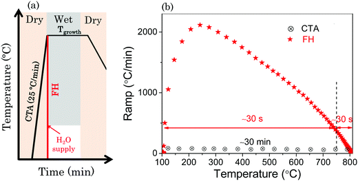
The YBCO precursor solutions used in this work were prepared by the trifluoroacetate (TFA) route as described in detail elsewhere26 with a metal concentration of 1.5 M. Essentially, the preparation of TFA–YBCO solution consisted in dissolution, in an inert atmosphere, of YBCO powder in an excess of trifluoroacetic anhydride, a small quantity of trifluoroacetic acid (Aldrich 99%) as a catalyst and recently distilled acetone as a solvent. A mixture of TFA salts (Ba(TFA)2, Cu(TFA)2 and Y(TFA)3) was then dissolved in sufficient anhydrous methyl alcohol or dry acetone to yield a solution with the corresponding metal ion concentration. This solution was stored in sealed vials, in an inert atmosphere. The viscosity was measured using a Haake RheoStress 600 rheometer reaching values of 2–5 mPa s. The metal stoichiometry was confirmed by titration analysis and the water content was evaluated using the Karl–Fischer method to be always <1 wt%. The films were prepared by single deposition spin coating the solution at 6000 rpm for 2 min on 5 × 5 mm2 (100) commercially available LaAlO3 (LAO) single-crystal substrates. Prior to the deposition of the solution onto the substrates high temperature annealing at 900 °C in an O2 flow for 300 min was performed to ensure a high quality and smooth substrate surface which then displays flat terraces separated by unit-cell high steps. After solution deposition, the coatings were pyrolyzed in a humid oxygen atmosphere to form uniform precursor films. The heating rate during the pyrolysis process was maintained at 3 K min−1 in the temperature range from 100 °C to 310 °C. Humid gas was injected by bubbling dry gas through deionized water (dew point 25 °C and P(H2O) = 23 mbar) into the furnace when the furnace temperature was higher than 110 °C.27 The gas flow was typically 0.07 l min−1 and annealing lasted for 30 min at 310 °C.Schematics of the thermal annealing profiles used in this work to crystallize the films after being pyrolyzed are shown in Scheme 1. Scheme 1(a) shows the general profiles of high temperature thermal treatments for the YBCO formation with optimized processing parameters.28–30 The conventional thermal annealing (CTA) process to grow YBCO films is characterized by a heating ramp of 25 °C min−1 while the FH process undergoes fast heating with an inconstant heating ramp (see Scheme 1(b)) which results in a short heating process of 1 min, i.e. with a total time reduction by a factor ∼30 as compared to CTA. Under both thermal conditions, the nucleation and growth occurred in a constant gas atmosphere: total pressure (PT = 1 bar), water partial pressure P(H2O) = 23 mbar, oxygen partial pressure (P(O2) = 0.2 mbar) and total gas flow (F = 0.6 l min−1). In this work, CTA was conducted with the introduction of humid gas during the heating process at 110 °C. In the case of the FH process, we conducted a systematic investigation of the influence of temperature where the humid gas is introduced (see the ESI†), and ultimately we focused our work on the humid gas atmosphere initiated at 110 °C during the heating process. After the crystallization thermal annealing process, we can obtain YBCO films with a thickness of 250 nm which was estimated by profilometry.
The microstructure and phase analyses of the quenched and fully converted YBCO thin films were carried out by two-dimensional (2D) X-ray diffraction (XRD) using a Bruker AXS General Area Detector Diffraction System (GADDS) diffractometer operating with Cu Kα radiation. This equipment allows rapid viewing of a large volume of reciprocal space within a single collection frame where epitaxial (single spots) and polycrystalline (ring-like patterns) reflections of the intermediate phase transition process during thermal process can be easily identified. The mean size of the crystalline precursor domains of the quenched films was determined according to the Debye–Scherrer formula by analyzing the peaks in the XRD patterns which were obtained integrating the area of the GADDS frames. The instrumental broadening of the Bruker AXS diffractometer was properly corrected through measurement of the integral breadth βi of a LaB6 reference sample. The absolute value of the nanoparticle diameter τ was calculated using the formula τ = (Kλ/βs![[thin space (1/6-em)]](https://www.rsc.org/images/entities/char_2009.gif) cos
cos![[thin space (1/6-em)]](https://www.rsc.org/images/entities/char_2009.gif) θ), where λ is the X-ray wavelength, βs is the line broadening of the FWHM of the XRD peak (in radian), after subtracting the instrumental broadening contribution βi, θ is the Bragg angle (in degree), and K is a dimensionless parameter (K = 0.9 for spherical particles). In our experiments the experimental total integral breadth was larger enough than the instrumental integral breadth, i.e. the nanoparticle sizes investigated were small enough (<35 nm).
θ), where λ is the X-ray wavelength, βs is the line broadening of the FWHM of the XRD peak (in radian), after subtracting the instrumental broadening contribution βi, θ is the Bragg angle (in degree), and K is a dimensionless parameter (K = 0.9 for spherical particles). In our experiments the experimental total integral breadth was larger enough than the instrumental integral breadth, i.e. the nanoparticle sizes investigated were small enough (<35 nm).
Nanostrain (ε) was determined using the Williamson–Hall (WH) method31,32 by analyzing the symmetric (00l) 2θ Bragg diffraction integral breadth acquired using a Siemens D5000 diffractometer. In-plane and out-of-plane texture analysis was conducted using the (103) YBCO phi-scan (ϕ-scan) and (005) YBCO rocking curve (ω-scan), respectively. The morphological characteristics of the films were investigated using scanning electron microscopy (SEM, FEI Quanta 200 FEG) in a planar view and in a transversal cut made by a focused ion beam (FIB). The microstructural scenario of the YBCO films was studied by scanning transmission electron microscopy (STEM) using a FEI Titan 60-300 microscope equipped with an X-FEG gun, a CETCOR probe corrector and a Gatan TRIDIEM 866 ERS energy filter operating in STEM mode at 300 kV. The critical current density (Jc), the superconducting transition temperature (Tc) and the transition width (ΔTc) were obtained from inductive measurements performed using a superconducting quantum interference device (SQUID) magnetometer (Quantum Design, San Diego, CA) equipped with a 7 T magnet. Hysteretic magnetization loops were measured to determine Jc(H) based on the Bean model while low field (μ0H ∼ 0.1 mT) magnetization measurements, following a Zero Field Cooled process, were used to determine Tc and ΔTc. The criteria used to determine ΔTc was 10–90% drop of the total magnetization.
3. Results and discussion
The main goal of this work is to develop an epitaxial YBCO film growth process with enhanced kinetics using a CSD approach. For this reason, we first investigated the intermediate phase transformations and the kinetic evolution of the nanoparticles leading to YBCO film growth. Finally, the microstructure and superconducting properties of the epitaxial films were also examined.Intermediate phase evolution and YBCO epitaxial growth
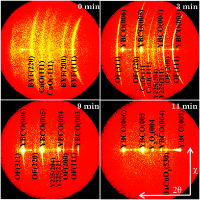
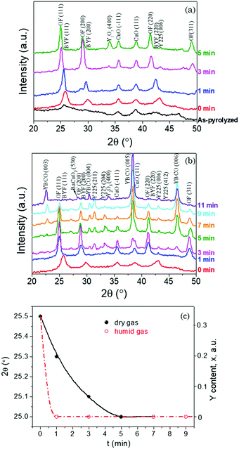
Fig. 1 displays the XRD GADDS patterns showing the intermediate phase evolution with time of films quenched after following a FH process up to 810 °C in a humid gas atmosphere (P(H2O) = 23 mbar, started at 110 °C). Fig. 2(a) and (b) show the corresponding θ–2θ integrated XRD patterns of FH thin films when a humid atmosphere is used together with those treated in a dry gas atmosphere. These XRD patterns allow us to follow the different phase transformation paths during the FH growth process and so analyze the path towards epitaxial YBCO thin films.After FH to the growth temperature, it is clearly seen from Fig. 1, 2(a) and (b) that all the quenched YBCO films consist of polycrystalline Ba1−xYxF2+x (BYF) and CuO phases. The θ–2θ XRD patterns show sharp BYF peaks, as compared with those of the as-pyrolyzed film, indicating strong recrystallization of BYF during the FH process. The results demonstrate, therefore, that no intermediate phase transformation occurs during the heating process of our novel FH growth route, in contrast to what has been previously revealed for TFA YBCO thin films grown based on the CTA growth process.33–37 In this scenario, all the intermediate phase transformations and YBCO formation are evidenced to occur at a selected high temperature, where supersaturation for YBCO nucleation and growth can be carefully tuned, thus promoting an enhanced control of the nucleation process.30,38,39
Upon annealing for different time periods at a constant temperature (810 °C), several relevant changes are observed. Overall, the formation process of YBCO follows the same chemical route which has been illustrated in detail in previous studies based on the CTA process;5,36,40,41 however, the kinetic effects are strongly relevant in our present conditions. The first trace of a compositional change is the liberation of Y from BYF solid solutions with the formation of barium oxyfluoride (OF). This is clearly illustrated by a shift of BYF Bragg peaks to smaller angle positions (Fig. 2(c)), indicating an increase of the lattice parameter of this fluorite structure.36,37 For instance, the BYF(111) peak moves from 2θ–25.5° to 2θ–25° when the Y content in BYF evolves from x = 0.33 to x = 0.11,36 As shown in Fig. 2(a) and (c), a complete conversion of BYF to OF is obtained after annealing for 3 min in a dry gas atmosphere. By contrast, this time is shortened to less than 1 min when films were annealed in a humid gas atmosphere, see Fig. 2(b) and (c). This phenomenon is in accordance with previous results which disclosed that water vapor facilitates this intermediate phase evolution releasing Y from the BYF solid solution.33 In films annealed in a dry atmosphere the formation of Y2O3 is clearly appreciated when the Y release from BYF is completed (Fig. 2(a)).
In the case of humid annealing, instead, the formation of crystalline Y2O3 is not clearly disclosed, while the formation of the Y225 phase is clearly appreciated. The difficulty in observing Y2O3 is due to peak overlap of the most intense Y2O3 peak (i.e. Y2O3(222) and BYF(002) peaks at 2θ ≈ 29°) although the appearance of the Y2O3 phase in the amorphous state cannot be discarded.36 It has been proposed by several authors11,42,43 that the formation of the Y225 phase from the reaction CuO + Y2O3 is probably a competing reaction towards the formation of YBCO directly from Y2O3.5,44
For films annealed in a humid gas atmosphere after FH, the first traces of YBCO nucleation are seen after annealing for 3 min, where the strongest YBCO peak appears at 2θ ≈ 38.5° as a shoulder of the CuO(111) peak. In the meantime, the intermediate Y225 phase appears at 2θ positions of 31.4°, 33.3° and 43.2° corresponding to the (211), (204) and (006) reflections, respectively. Upon annealing, a gradual weakened XRD diffraction pattern of OF and CuO peaks can be observed, together with the increase of YBCO and Y225 peaks. Finally, a fully converted YBCO film can be achieved after annealing at 810 °C in a humid gas atmosphere for 11 min, even though some secondary phases (Y225, Y2O3 or BaCuO2) could remain at impurity levels. For the films quenched in a dry gas atmosphere, instead, no traces of the Y225 phase are seen after 5 min of annealing while no YBCO nucleation is observed in the present annealing time range. This confirms that a humid atmosphere is required to form YBCO while the formation of the competing Y225 phase is kinetically hindered in a dry atmosphere.
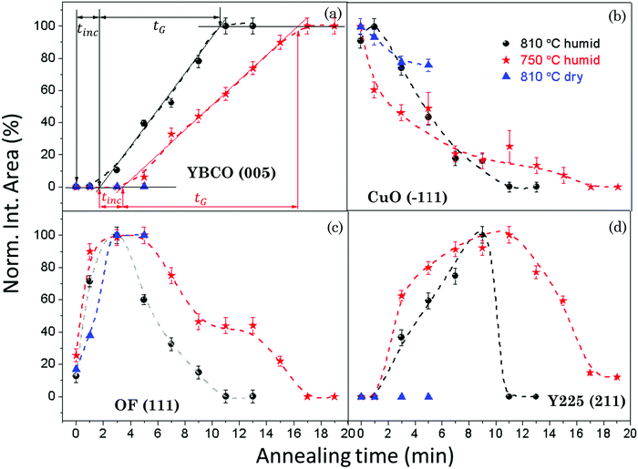
In order to quantitatively draw the phase evolution trend and follow the formation kinetics of YBCO with annealing time under different growth conditions, we integrated the area under the corresponding XRD peaks of the selected phases, such as YBCO(005), CuO(−111), OF(111) and Y2Cu2O5(211). The evolution trends of the selected phases for the films quenched under different growth conditions are shown in Fig. 3(a)–(d), in which the annealing time dependence of the integrated areas of the selected XRD peaks is shown after normalizing to the maximum value for each one obtained in the studied thermal process.
Fig. 3(a) shows the evolution of the YBCO(005) intensity with annealing time, for the films grown under different conditions. Analyzing the series of integrated intensity vs time plots for films quenched under different thermal annealing conditions, we can investigate the nucleation and growth kinetics of the YBCO phase formation. It is straightforward to note that, in the FH growth process, the c-axis nucleation event of the YBCO phase fully occurs at the selected annealing temperatures, as discussed before. The formation of YBCO nuclei after some annealing time before a linear increase of the intensity of the (005) Bragg reflection is achieved, i.e. there exists an incubation time tinc before a stable YBCO film growth exists. This phenomenon is strongly related to the kinetics of the Volmer–Weber nucleation process, controlled by the nucleation rate of YBCO islands  .3,45 This parameter determines the density of stable nuclei formed under suitable thermodynamic conditions for nucleation. The nucleation process, however, is a thermally activated kinetic process depending in general on the atomic mobility and the energy barrier ΔG* to form stable nuclei. However, limitations from atomic diffusion are usually neglected at a high enough temperature in most systems, if the nanoscale homogeneity is preserved,45 and thus, the nucleation rate can be written as (eqn (1-1)):5
 | (1-1) |
 is the nucleation rate at a negligible nucleation barrier, ΔG* ≈ 0. In this scheme we can identify the time integration of
  until the YBCO phase is observable through the XRD patterns as the incubation time tinc. This represents the total time consumed at the annealing temperature until a stable growth rate of YBCO is achieved. Obviously, the tinc values estimated in Fig. 3(a) are ∼3.4 min and ∼1.7 min for films thermally treated at 750 °C and 810 °C, respectively. These time periods are significantly decreased (by factors 3–5) as compared to the films grown by the CTA heating route, as detected by in situ electrical conductance measurements39,46,47 or X-ray diffraction.36,39 Very likely, the fundamental reason for such a reduced incubation time is the smaller atomic diffusion lengths needed to form stable nuclei which then enhances the nucleation rate. This is an issue that is investigated in the next section. We should also note that the observed enhanced nucleation rate corresponds to the c-axis oriented grains while no a-axis grain nucleation is observed, even when growing at 750 °C, a temperature where usually the supersaturation degree is high enough in CTA YBCO films to already display a certain amount of a-axis grain nucleation.28,39
After having identified the nucleation events of FH films, the film growth time (tG) is defined as the total time consumed during the linear increase of the (005) peak intensity until a full conversion of the YBCO phase is achieved. This allows the estimation of the YBCO growth rate along the c-axis. We have estimated for our FH films that the growth rates at P(H2O) = 23 mbar are 0.47 nm s−1 and 0.32 nm s−1, at 810 °C and 750 °C, respectively, in agreement with the values determined in films grown by CTA,46,47 deduced in both cases from in situ resistance measurements.
In addition to the analysis of the YBCO formation, qualitative imaging of the evolution with time of other intermediate phases, such as CuO, OF and Y225, was performed following the intensity of specific Bragg peaks. These results are shown in Fig. 3(b)–(d). Fig. 3(b) shows that the intensity of the CuO(−111) peak decreases constantly and vanishes at the time where a full conversion of the YBCO phase is reached. This result indicates that CuO participates in the conversion reactions towards both Y225 and YBCO phases during the isothermal process, following the reaction routes previously proposed in CTA growth.5,36 In Fig. 3(c), we observe an initial sharp increase of the intensity of the OF(111) peak reaching the maximum value after annealing for ∼3–5 min when YBCO growth is initiated. Very likely this increase of the Bragg peak intensity is associated with an enhanced crystallinity of this phase during the high temperature annealing. Ba oxyfluoride OF is prone to form a well-ordered and large coherent lattice during the high temperature thermal treatment in the CTA process.11,48 In the present FH process only polycrystalline features of the OF phase are observable in the GADDS frame (see Fig. 1). This phase has been claimed in CTA films to be one of the precursors for the formation of the YBCO phase due to the low barrier of YBCO nucleation sites provided by the (111)-oriented OF domains.11,49 Actually, this phase plays an important role in the YBCO formation reactions.39 The primary YBCO formation reaction in the FH growth process follows the same reaction route as CTA: Ba(OxFy)2 + ![[/]](https://www.rsc.org/images/entities/char_e0ee.gif) CuO + ¼Y2O3 + yH2O(s) → ½YBa2Cu3O6.5 + 2yHF(s).5,29,41
CuO + ¼Y2O3 + yH2O(s) → ½YBa2Cu3O6.5 + 2yHF(s).5,29,41
Meanwhile the formation of an intermediate phase and a competing reaction previously identified in CTA film growth, i.e. Y2O3 + CuO → Y2Cu2O5 and Y2Cu2O5 + 4BaO + 4CuO → 2YBa2Cu3O7−x,5,39 also take place in the FH films, as shown in Fig. 1, 2(b) and 3(d). After annealing for ∼1–3 min in a humid gas atmosphere, Y2Cu2O5 and YBCO phases are formed following similar kinetic effects, and so it is very likely that the two competing reactions leading to YBCO occur simultaneously.36 Finally, the OF(111) and Y2Cu2O5(211) intensities vanish at the same time that the YBCO phase is fully converted.
In contrast to annealing in a humid atmosphere, no crystalline Y2Cu2O5(211) is observed when annealing is conducted in a dry atmosphere during the studied annealing time, see Fig. 2(a) and 3(d). This is probably due to both the delay in the liberation of Y ions from the BYF phase and to the kinetic limitations of the reaction under a dry atmosphere. We should also note that no YBCO is formed when annealing is performed in a dry atmosphere because Ba2+ ions are not liberated from the OF precursor.
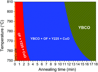
As a concise representation of the intermediate phase transformation paths and growth kinetics, we have set up a schematic kinetic phase diagram defining different areas of phase coexistence for the YBCO films grown by the FH process in a humid atmosphere, as shown in Fig. 4. As a general trend, we can state that the YBCO precursor films experienced the same phase transformations previously observed with the commonly used conventional heating rates.5,36 It is seen that the kinetics for the intermediate phase transformations towards the YBCO phase are slightly slower when the temperatures decrease. However, what is really remarkable is that this diagram reconfirms that the FH process can indeed provide a much faster overall growth kinetics, i.e. the windows of the intermediate phase transformation before YBCO formation are significantly compressed compared with the CTA growth process.36 Therefore, the main source of the fastened growth of YBCO films is the shortening of the nucleation (or incubation) time of YBCO nuclei while the growth time of the films is very similar in both cases.
Kinetic evolution of nanocrystalline precursors
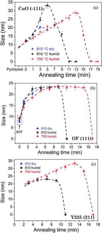
A very important phenomenon that affects the nucleation/growth process and the eventual microstructure of epitaxial YBCO films is the coarsening of the nanocrystalline precursor phases (CuO, Y225 and OF). It has been reported earlier that processing parameters such as gas humidity, heating rate, growth temperature and annealing time induce size changes of the CuO nanoparticle precursors during either pyrolysis50–52 or the following growth11,51,53 process. In previous studies,9,50–54 it has been suggested that inhomogeneous segregation of CuO associated with the coarsening effect leads to non-uniform YBCO crystallization and then large pores may remain which ultimately affect negatively the superconducting properties of YBCO thin films. In this respect, it is clear that a fine control of precursor nanoparticle size, as well as maintaining a homogeneous distribution during the thermal processing procedure, is of significant importance for determining the final film quality and homogeneity of the YBCO films. We investigated therefore the coarsening process of the intermediate nanocrystalline phases using X-ray diffraction.Fig. 5(a) shows the CuO nanoparticle size evolution with the annealing time of the films annealed under the following thermal processing conditions: at 810 °C in a dry gas atmosphere, at 810 °C in a humid gas atmosphere and at 750 °C in a humid gas atmosphere. The grain size of the CuO nanoparticles is estimated from the integral breadth of XRD reflections by the Debye–Scherrer formula using the (−111) Bragg peak of CuO. The mean size of the CuO nanoparticles is estimated to be ∼8 nm for films after pyrolysis. It is worth noting that the CuO nanoparticle size only slightly increases during the FH process while the size monotonically increases during the following isothermal annealing process until reaching maximum values of 20 ± 1 nm, 33 ± 1 nm and 29 ± 1 nm for films annealed at 810 °C in dry gas, at 810 °C in humid gas and at 750 °C in humid gas after annealing for 3, 5 and 13 min, respectively. The size of these nanocrystalline phases is considerably smaller than those obtained in the YBCO thin films prepared following the CTA process, where CuO nanoparticles with a size up to ∼100 nm were observed by TEM.5,11,51,53 We also note that a remarkable decline of the nanoparticle size is detected after a certain maximum. This is due to the significant consumption of the CuO phase during the annealing process and resulting in increased YBCO and Y225 peak intensities (see Fig. 3(a) and (d)). For films annealed at 810 °C in a humid gas atmosphere, the CuO nanoparticle exhibits a more drastic coarsening (∼4 nm min−1), as compared to films annealed at 810 °C in a dry gas atmosphere (∼1 nm min−1). It is clear, in any case, that for the films annealed in the same humid atmosphere, a lower growth temperature leads to a smoother coarsening effect of CuO nanoparticles (∼1 nm min−1 at 750 °C). We attribute this phenomenon to the thermally activated behavior of atomic diffusion which enhances kinetic effects thus leading to a drastic size evolution of CuO at high temperatures in a humid gas atmosphere.45
Moreover, we also investigated the particle size evolution of two important nanocrystalline reactants, i.e. OF and Y225, as shown in Fig. 5(b) and (c). The mean nanoparticle size of both phases shows a similar trend to that of CuO, with an initial increase due to coarsening, followed by reduction associated with the consumption for YBCO formation. For the BYF and OF phases, the dependence with the annealing time shows an initial size increase rate of 3–4 nm min−1, followed by a quite smooth behavior saturating to a mean size of 22 ± 2 nm, independent of the atmosphere, after annealing for ∼3 min, and finally they are completely consumed to form YBCO. Concerning the Y225 phase, its mean nanoparticle size maintains an initial persistent coarsening rate (∼1 nm min−1) since the nucleation event with a particle size of ∼20 nm up to ∼35 nm for films annealed at 750 °C in humid gas. This is in contrast to those annealed at 810 °C in humid gas where the fast transformation to YBCO avoids the coarsening process. The continuous coarsening with time of the Y225 nanoparticles at 750 °C suggests a sluggish consumption of this phase, thus confirming the low reaction kinetics displayed by the intermediate reaction Y2Cu2O5 + 4BaO + 4CuO → 2YBa2Cu3O7−x.
In conclusion, we have shown that the kinetic evolution of the nanoparticle precursors is fast enough to have a very relevant influence on the nucleation events of YBCO epitaxial islands. We associate the strong decrease of the YBCO nucleation time (enhanced nucleation rate) in the FH films with the preservation of the precursor nanoparticle size below ∼30 nm, instead of more than ∼100 nm in the CTA films.
Film growth, microstructure and superconducting properties
After an extended investigation of the chemical and microstructural evolution of the intermediate phases leading to YBCO film formation, we report here an investigation of the epitaxial film formation and the influence on the microstructure and superconducting properties. The main goal is to achieve a high quality film epitaxy to avoid the formation of high angle grain boundaries thereby achieving high critical current densities.All the films presented in this section were grown by FH in a wet atmosphere and in a humid atmosphere starting at 110 °C. This is an important choice because the microstructural evolution of the films strongly differs when the water atmosphere is initiated at lower or higher temperatures (see the ESI†). Essentially, the choice of the temperature where the humid atmosphere is created modifies the porosity of the film with the solid oxide and fluoride precursors. This characteristic, in turn, modifies the kinetics and the supersaturation degree of the solid–gas reaction leading to YBCO formation, as well as the final microstructure and superconducting performance (see Fig. S1–S4 in the ESI†).
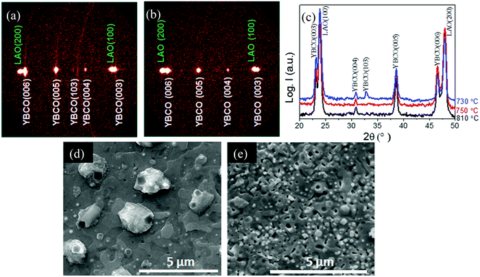
Fig. 6(a) and (b) show two typical GADDS XRD patterns and Fig. 6(c) shows the integrated θ–2θ patterns of the films grown at different temperatures in the range 730 °C to 810 °C. It is clearly seen that c-axis growth is achieved above 750 °C, while the films grown at 730 °C display some random orientation as well, as evidenced by the diffraction ring corresponding to the (103) Bragg peak observed in Fig. 6(a). When film growth is performed at higher temperatures, for instance at 840 °C, some residual impurities are observed such as Y2O3. The SEM images of typical FH films displaying c-axis growth are shown in Fig. 6(d) and (e) where it is appreciated that the films show a negligible porosity and a strong grain connectivity, similarly to optimal CTA films.5,55 The lattice and texture quality of the c-axis oriented films grown at 750 °C was evaluated by measuring the FWHM of ω-scan ((005) peak) and ϕ-scan ((103) peak), c parameter and nanostrain. The c parameter was ∼11.691 ± 0.010 Å, while Δω = 0.62° and Δϕ = 1.29°, revealing therefore a good out-of-plane and in-plane texture quality, similar to that observed in CTA films. The nanostrain of the FH films, on the other hand, show a significant increase, as compared to the CTA films, reaching ε = 0.25% instead of ε = 0.11%.24,55,56 This enhanced values of nanostrain in pristine FH films appear to be similar to those observed in nanocomposite YBCO thin films grown by CTA where a high density of intergrowths is usually observed.24,56
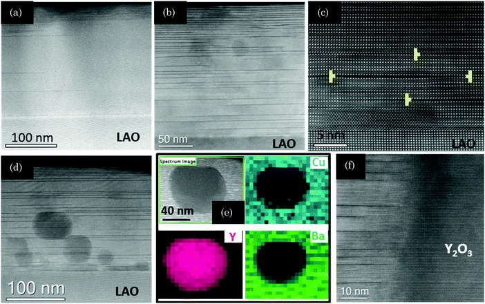
To investigate the microstructure of pristine FH YBCO films we obtained cross sectional TEM images and compared them with those obtained for films grown by CTA. Fig. 7(a) and (b) show typical low resolution images of the films grown at 810 °C by CTA and at 750 °C by FH, respectively, where the dark stripes parallel to the (00l) planes correspond to Y248 intergrowths. The structure of these planar defects and its influence on the superconducting properties of YBCO films and coated conductors have been reported recently.23 Note that the YBCO film grown by FH displays a high density of intergrowths while the CTA film has a much lower concentration of such defects. It is also noticeable that the YBCO matrix of the FH film grown at 750 °C is free of any secondary phase, an issue that did not happen in the FH films grown at 810 °C by FH (see Fig. 7(d)–(f)) where some residual Y2O3 nanoparticles are observed. It has already been demonstrated, in several previous studies, that the Y248 intergrowths are responsible for increasing the nanostrain owing to the fact that these intergrowths are surrounded by partial dislocations (see for instance Fig. 7(c)). Therefore, we conclude that the FH YBCO films display a modified nanostructure, as reflected by a higher nanostrain and a larger concentration of intergrowths, an issue that will certainly influence the superconducting properties.
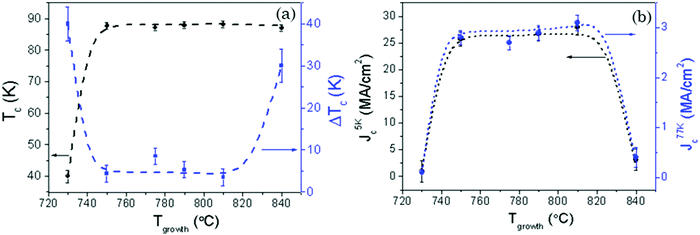
Fig. 8(a) and (b) show the growth temperature (730–840 °C) dependence of superconducting properties, including Tc, ΔTc, Jc(5 K) and Jc(77 K) which are measured at self-field. Note that the films grown at 750–810 °C display an optimal self-field critical current density, following the trend of the films having high quality microstructural features mentioned above (c-axis nucleation, high compositional purity, and good texture quality). On the other hand, the superconducting performance drops significantly when the growth process is carried out at 730 °C or at 840 °C. In the first case, this accounted for the high-angle grain boundaries created between the randomly oriented and (00l)-oriented YBCO grains.5 In the second case, the self-field Jc drop is due to the high density of secondary phase nanoparticles which have a current blocking effect. It is noteworthy that faintly constant superconducting properties are obtained in a large optimal growth temperature window (750–810 °C), as compared to CTA grown pristine films,28,39 although a precipitate-free film was only obtained when the growth was conducted at 750 °C. The enlarged temperature window with optimal superconducting properties is correlated with the enlarged window for c-axis YBCO nucleation and so we conclude that the enhanced nucleation rate discussed before provides ultimately a strong benefit in improving the microstructure of the films.
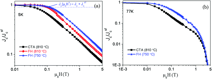
Additional evidence of the enhanced superconducting properties was obtained from the analysis of the magnetic field dependence of the critical current density Jc(H). Fig. 9(a) and (b) show the magnetic field dependence of the normalized critical current density (Jc(H)/Jsfc) measured at both 5 K and 77 K. An overall smoother Jc(H) dependence is observed in films grown by FH at different temperatures, as compared with the CTA YBCO thin films. For instance, Jc(H)/Jsfc at 5 T and 5 K is enhanced by a factor ∼2. This enhanced pinning efficiency can be quantified by determining the evolution of the crossover magnetic field μ0H*. The magnetic field μ0H* is experimentally determined as the field where the Jc(H) plateau (Fig. 9(a)) decreases by 10% and it is assigned to the crossover field between a single vortex pinning regime and a collective pinning regime.25 Therefore, μ0H* is an indication of the density and effectiveness of individual pinning centers which in the present pristine YBCO films are mainly associated with the measured nanostrain arising from the highly distorted YBCO matrix.
Although all the films grown by FH show similar nanostrain values, the highest μ0H* values are those of the films grown at 750 °C. Specifically, μ0H* increases from 37.8 mT (CTA YBCO) and 101.2 mT (FH (810 °C)) to 116.2 mT (FH (750 °C)), i.e. an increase by a factor 3 in pinning effectiveness as compared to CTA. This enhanced vortex pinning efficiency is associated with the larger concentration of Y248 intergrowths described before from the TEM images for the FH films produced at 750 °C. Our results, therefore, are in agreement with previous claims that the density and the length of Y248 intergrowths in YBCO share the main responsibility for the observed improvement of pinning efficiency.25,56
4. Conclusions
We have demonstrated that a novel flash heating process to grow YBCO thin films on LaAlO3 single crystalline substrates shows several advantages as compared to the conventional thermal annealing process, typically with a heating rate about 30 times lower. Through an investigation of the evolution of the intermediate nanocrystalline phases by means of X-ray diffraction of quenched films, we conclude that no phase transformation occurs during heating while coarsening of the nanocrystalline precursors is strongly limited. This minimized evolution of the intermediate precursors allows maintaining an homogeneous landscape at the nanoscale and this, in turn, results in an enhanced epitaxial nucleation rate of YBCO due to the shortening of the diffusion lengths and thus the annealing time to grow the films. An additional advantage of FH is that having achieved a larger nucleation rate allows the induction of c-axis nucleation at lower temperatures. This is a very appealing feature to facilitate the fabrication of coated conductors because interfacial reactivity is minimized at low temperatures and thus the film texture quality is preserved and so higher superconducting performances may be achieved. The reaction paths under isothermal annealing conditions were investigated and we conclude that they follow the same phase transformations and chemical reactions as those in conventional thermal annealing, although with a different kinetic behavior.Finally, we have shown that growing solution derived YBCO films at reduced temperatures (∼750 °C) leads to a modified nanoscale defect structure of the films. A larger concentration of intergrowths was achieved increasing the nanostrain intensity and hence the vortex pinning efficiency, i.e. a smoother magnetic field dependence of the critical current density has been demonstrated. This feature will be also very useful in the development of nanocomposite superconductors where the nanoparticle size may be reduced at low growth temperatures and this leads to enhanced vortex pinning capability. In conclusion, the flash heating process leads to films more appealing for power applications where large performances under high magnetic fields are required.
Conflicts of interest
There are no conflicts to declare.Acknowledgements
The authors acknowledge the EUROTAPES project (EU-FP7 NMP-LA-2012-280432), COACHSUPENERGY (MAT2014-51778-C2-1-R from MINECO) (co-financed by the European Regional Development Fund), 2017-SGR 1519 from Generalitat de Catalunya, and COST Action NANOCOHYBRI (CA16218). The ICMAB authors acknowledge the Center of Excellence award Severo Ochoa SEV-2015-0496. The authors acknowledge the Scientific Services at ICMAB, ICN2 Electron Microscopy Division. Z. L. acknowledges the China Scholarship Council (CSC).References
- F. F. Lange, Science, 1996, 273, 903–909 CrossRef CAS PubMed.
- R. W. Schwartz, T. Schneller and R. Waser, C. R. Chim., 2004, 7, 433–461 CrossRef CAS.
- X. Obradors, T. Puig, M. Gibert, A. Queralto, J. Zabaleta and N. Mestres, Chem. Soc. Rev., 2014, 43, 2200–2225 RSC.
- N. Bassiri-Gharb, Y. Bastani and A. Bernal, Chem. Soc. Rev., 2014, 43, 2125–2140 RSC.
- X. Obradors, T. Puig, S. Ricart, M. Coll, J. Gazquez, A. Palau and X. Granados, Supercond. Sci. Technol., 2012, 25, 123001 CrossRef.
- A. Gupta, R. Jagannathan, E. I. Cooper, E. A. Giess, J. I. Landman and B. W. Hussey, Appl. Phys. Lett., 1988, 52, 2077–2079 CrossRef CAS.
- T. Araki and I. Hirabayashi, Supercond. Sci. Technol., 2003, 16, R71 CrossRef CAS.
- X. Obradors, T. Puig, A. Pomar, F. Sandiumenge, N. Mestres, M. Coll, A. Cavallaro, N. Roma, J. Gazquez and J. Gonzalez, Supercond. Sci. Technol., 2006, 19, S13 CrossRef CAS.
- T. G. Holesinger, L. Civale, B. Maiorov, D. M. Feldmann, J. Y. Coulter, D. J. Miller, V. A. Maroni, Z. Chen, D. C. Larbalestier, R. Feenstra, X. P. Li, M. B. Huang, T. Kodenkandath, W. Zhang, M. W. Rupich and A. P. Malozemoff, Adv. Mater., 2008, 20, 391–407 CrossRef CAS.
- I. Bretos, R. Jiménez, J. Ricote and M. Calzada, Chem. Soc. Rev., 2018, 47, 291 RSC.
- J. Gazquez, F. Sandiumenge, M. Coll, A. Pomar, N. Mestres, T. Puig, X. Obradors, Y. Kihn, M. J. Casanove and C. Ballesteros, Chem. Mater., 2006, 18, 6211–6219 CrossRef CAS.
- D. Larbalestier, A. Gurevich, D. M. Feldmann and A. Polyanskii, Nature, 2001, 414, 368–377 CrossRef CAS PubMed.
- A. Malozemoff, S. Fleshler, M. Rupich, C. Thieme, X. Li, W. Zhang, A. Otto, J. Maguire, D. Folts and J. Yuan, Supercond. Sci. Technol., 2008, 21, 034005 CrossRef.
- Y. Shiohara, T. Taneda and M. Yoshizumi, Jpn. J. Appl. Phys., 2011, 51, 010007 CrossRef.
- X. Obradors and T. Puig, Supercond. Sci. Technol., 2014, 27, 044003 CrossRef.
- D. C. Larbalestier, J. Jiang, U. P. Trociewitz, F. Kametani, C. Scheuerlein, M. Dalban-Canassy, M. Matras, P. Chen, N. C. Craig, P. J. Lee and E. E. Hellstrom, Nat. Mater., 2014, 13, 375–381 CrossRef CAS PubMed.
- C. Senatore, M. Alessandrini, A. Lucarelli, R. Tediosi, D. Uglietti and Y. Iwasa, Supercond. Sci. Technol., 2014, 27, 103001 CrossRef.
- A. Malozemoff, Annu. Rev. Mater. Res., 2012, 42, 373–397 CrossRef CAS.
- A. Queraltó, D. L. M. Maria, J. Arbiol, X. Obradors and T. Puig, Adv. Mater. Interfaces, 2016, 3, 1600392 CrossRef.
- A. D. Li, W. Di, H. Q. Ling, W. Mu, Z. Liu and N. Ming, J. Cryst. Growth, 2002, 235, 394–400 CrossRef CAS.
- Q. Y. Ma, T. J. Licata, X. Wu, E. S. Yang and C. Chang, Appl. Phys. Lett., 1988, 53, 2229–2231 CrossRef CAS.
- M. Erbe, J. Hänisch, T. Freudenberg, A. Kirchner, I. Mönch and S. Kaskel, J. Mater. Chem. A, 2014, 2, 4932–4944 RSC.
- J. Gazquez, R. Guzman, R. Mishra, E. Bartolomé, J. Salafranca, C. Magén, M. Varela, M. Coll, A. Palau, S. M. Valvidares, P. Gargiani, E. Pellegrin, J. Herrero-Martin, S. J. Pennycook, S. T. Pantelides, T. Puig and X. Obradors, Adv. Sci., 2016, 3, 1500295 CrossRef PubMed.
- A. Llordés, A. Palau, J. Gázquez, M. Coll, R. Vlad, A. Pomar, J. Arbiol, R. Guzman, S. Ye, V. Rouco, F. Sandiumenge, S. Ricart, T. Puig, M. Varela, D. Chateigner, J. Vanacken, J. Gutiérrez, V. Moshchalkov, G. Deutscher, C. Magen and X. Obradors, Nat. Mater., 2012, 11, 329–336 CrossRef PubMed.
- A. Palau, F. Vallès, V. Rouco, M. Coll, Z. Li, C. Pop, B. Mundet, J. Gàzquez, R. Guzman, J. Gutierrez, X. Obradors and T. Puig, Supercond. Sci. Technol., 2018, 31, 034004 CrossRef.
- N. Roma, S. Morlens, S. Ricart, K. Zalamova, J. M. Moreto, A. Pomar, T. Puig and X. Obradors, Supercond. Sci. Technol., 2006, 19, 521 CrossRef CAS.
- A. Llordes, K. Zalamova, S. Ricart, A. Palau, A. Pomar, T. Puig, A. Hardy, M. K. Van Bael and X. Obradors, Chem. Mater., 2010, 22, 1686–1694 CrossRef CAS.
- T. Puig, J. C. González, A. Pomar, N. Mestres, O. Castaño, M. Coll, J. Gázquez, F. Sandiumenge, S. Piñol and X. Obradors, Supercond. Sci. Technol., 2005, 18, 1141–1150 CrossRef CAS.
- H. Chen, K. Zalamova, A. Pomar, X. Granados, T. Puig and X. Obradors, Supercond. Sci. Technol., 2010, 23, 034005 CrossRef.
- H. Chen, K. Zalamova, A. Pomar, X. Granados, T. Puig and X. Obradors, J. Mater. Res., 2011, 25, 2371–2379 CrossRef CAS.
- G. Williamson and W. Hall, Acta Metall., 1953, 1, 22–31 CrossRef CAS.
- N. Popa, J. Appl. Crystallogr., 1998, 31, 176–180 CrossRef CAS.
- W. Dou, Z. Liu, C. Peng, C. Bai, Y. Lu, Y. Guo and C. Cai, J. Supercond. Novel Magn., 2016, 29, 1997–2001 CrossRef CAS.
- W. Wu, F. Feng, Y. Zhao, X. Tang, J. C. Grivel, Z. Han, Z. Hong and Z. Jin, IEEE Trans. Appl. Supercond., 2016, 26, 1–5 Search PubMed.
- K. Vandaele, M. Mosiadz, S. C. Hopkins, A. Patel, I. Van Driessche and B. A. Glowacki, Mater. Res. Bull., 2012, 47, 2032–2039 CrossRef CAS.
- K. Zalamova, A. Pomar, A. Palau, T. Puig and X. Obradors, Supercond. Sci. Technol., 2009, 23, 014012 CrossRef.
- D. E. Wesolowski, M. Yoshizumi and M. J. Cima, Phys. C, 2006, 450, 76–82 CrossRef CAS.
- Y. Ichino, K. Sudoh, K. Miyachi, Y. Yoshida and Y. Takai, IEEE Trans. Appl. Supercond., 2003, 13, 2735–2738 CrossRef CAS.
- X. Obradors, F. Martínez-Julián, K. Zalamova, V. R. Vlad, A. Pomar, A. Palau, A. Llordés, H. Chen, M. Coll, S. Ricart, N. Mestres, X. Granados, T. Puig and M. Rikel, Phys. C, 2012, 482, 58–67 CrossRef CAS.
- W. Wong-Ng, I. Levin, L. Cook and R. Feenstra, Appl. Phys. Lett., 2006, 88, 102507 CrossRef.
- V. Solovyov, I. K. Dimitrov and Q. Li, Supercond. Sci. Technol., 2012, 26, 013001 CrossRef.
- W. Wong-Ng, I. Levin, R. Feenstra, L. P. Cook and M. Vaudin, Supercond. Sci. Technol., 2004, 17, S548 CrossRef CAS.
- M. Yoshizumi, I. Seleznev and M. J. Cima, Phys. C, 2004, 403, 191–199 CrossRef CAS.
- T. Izumi and K. Nakaoka, Supercond. Sci. Technol., 2018, 31, 034008 CrossRef.
- A. Queralto, M. de la Mata, J. Arbiol, R. Hühne, X. Obradors and T. Puig, Cryst. Growth Des., 2017, 17, 504–516 CrossRef CAS.
- C. F. Sánchez-Valdés, T. Puig and X. Obradors, Supercond. Sci. Technol., 2015, 28, 024006 CrossRef.
- T. Qu, Y. Zhu, F. Feng, G. Lin, S. Deng, H. Lu, X. Zhang, Q. Fu, S. Xiao, P. Zeng and Z. Han, IEEE Trans. Appl. Supercond., 2016, 26, 1–5 Search PubMed.
- A. A. Armenio, A. Augieri, L. Ciontea, G. Contini, I. Davoli, M. D. Giovannantonio, V. Galluzzi, A. Mancini, A. Rufoloni and T. Petrisor, Supercond. Sci. Technol., 2011, 24, 115008 CrossRef.
- L. Wu, Y. Zhu, V. F. Solovyov, H. J. Wiesmann, A. R. Moodenbaugh, R. L. Sabatini and M. Suenaga, J. Mater. Res., 2001, 16, 2869–2884 CrossRef CAS.
- T. Araki, I. Hirabayashi, J. Shibata and Y. Ikuhara, Supercond. Sci. Technol., 2002, 15, 913 CrossRef CAS.
- J. Matsuda, K. Nakaoka, T. Izumi, Y. Yamada and Y. Shiohara, Phys. C, 2008, 468, 1017–1023 CrossRef CAS.
- J. Matsuda, K. Nakaoka, R. Teranishi, Y. Kitoh, Y. Aoki, H. Fuji, Y. Yamada, T. Izumi and Y. Shiohara, Phys. C, 2006, 445, 563–569 CrossRef.
- J. Matsuda, K. Nakaoka, Y. Sutoh, T. Nakanishi, M. Yoshizumi, Y. Yamada, T. Izumi and Y. Shiohara, Phys. C, 2007, 463, 712–716 CrossRef.
- R. Feenstra, F. A. List, Y. Zhang, D. K. Christen, V. A. Maroni, D. J. Miller and D. M. Feldmann, IEEE Trans. Appl. Supercond., 2007, 17, 3254–3258 CAS.
- C. Pop, B. Villarejo, F. Pino, B. Mundet, S. Ricart, M. de Palau, T. Puig and X. Obradors, Supercond. Sci. Technol., 2019, 32, 015004 CrossRef.
- M. Coll, R. Guzman, P. Garcés, J. Gazquez, V. Rouco, A. Palau, S. Ye, C. Magen, H. Suo, H. Castro, T. Puig and X. Obradors, Supercond. Sci. Technol., 2014, 27, 044008 CrossRef.
Footnote |
| † Electronic supplementary information (ESI) available: FIB results showing the inner porosity evolution of as-pyrolyzed films during the crystallization thermal annealing stage, the investigation of the influence of water introduction time on the microstructure and superconducting properties of YBCO films which were grown using the FH process. See DOI: 10.1039/c9tc00488b |
| This journal is © The Royal Society of Chemistry 2019 |

