
Chiral nematic latex–GO composite films with synchronous response of color and actuation†
Juanjuan
Sun
a,
Xingxiang
Ji
a,
Guihua
Li
a,
Yu
Zhang
a,
Na
Liu
a,
Hongguang
Li
 *b,
Menghua
Qin
*c and
Zaiwu
Yuan
*a
*b,
Menghua
Qin
*c and
Zaiwu
Yuan
*a
aState Key Laboratory of Biobased Material and Green Papermaking & Key Laboratory of Fine Chemicals in Universities of Shandong, Qilu University of Technology (Shandong Academy of Sciences), 250353, Jinan, China. E-mail: yuanzaiwu@163.com
bKey Laboratory of Colloid and Interface Chemistry, Ministry of Education, Shandong University, Jinan, 250100, China. E-mail: hgli@sdu.edu.cn
cLaboratory of Organic Chemistry, Taishan University, 271021, Taian, China. E-mail: qmh@qlu.edu.cn
First published on 21st November 2018
Abstract
We report the preparation of flexible latex/graphene oxide (GO) composite films templated by cellulose nanocrystals (CNCs), which show dual responses with interesting color and morphological changes toward water. First, ternary composite films with chiral nematic order were prepared via evaporation-induced self-assembly (EISA) of an aqueous dispersion containing latex, GO and CNCs. Driven by the difference in gravity and the increase of entropy, uneven distribution of GO occurs with the majority gathering at the top of the film. In the second step, CNCs were selectively etched by alkali treatment, leading to the formation of latex/GO (LG) composite films which retain the chiral nematic order and the asymmetric distribution of GO. Meanwhile, the flexibility of the film has been greatly improved. The asymmetrically-organized LG film has different wettability on the top and bottom surfaces, which induces varying extent of swelling toward water. As a result, the synchronous response of color and actuation was realized. Compared to other two-dimensional actuators, the LG films presented in this work have the advantage of easy preparation and additional color change. In addition, the films are also more robust than those with a bilayer structure, which tend to delaminate during repeated utilization.
Introduction
Ordered nanomaterials are attractive because of their numerous applications in electronics,1 optics,2,3 magnetics,4 energy storage5 and electrochemistry.6 Of particular interest are the self-assembled nanostructures formed by rod-like particles such as DNA fragments,7 tobacco mosaic viruses8 and crystallites extracted from polysaccharides.9 As the most abundant natural polymer, cellulose can be obtained from a variety of natural resources and has drawn rapidly growing interest due to its wide applications in manufacturing household and industrial products. Cellulose nanocrystals (CNCs), a crystalline form of cellulose, can be used to construct ordered materials with rich functionalities.10–12 For example, one-dimensional photonic crystals with chiral nematic structure can be facilely obtained via evaporization-induced self-assembly (EISA),13 which imitate the iridescent cuticles of crustaceans and insects.14 In addition, various inorganic hard materials can be prepared by using CNCs as templates, which have found applications in anti-counterfeiting, catalysis, gas separation and sensing.15–21Smart actuators can directly convert external stimulations to mechanical energy by reversible structural changes.22,23 They have drawn considerable attention due to their wide range of applications in various intelligent devices such as chemical sensors,24 sensitive switches,25 artificial muscles,26 microrobotics,27 optical displays28 and prosthetic devices.29 As a powerful technique to prepare two-dimensional ordered structures, EISA has been applied to prepare actuators. For example, Khan et al. fabricated bilayer resin films with chiral nematic structure via a two-step EISA.30 The films have traditional two-layered structures where the two layers have the same composition but different helical pitches.
Graphene oxide (GO) and its reduced form (rGO), which are promising two-dimensional nanomaterials, have recently emerged as new types of materials for actuators.31–37 Integration of GO (or rGO) into CNC-based films has also been reported38–40 where the films were prepared by vacuum-assisted self-assembly (VASA) of an aqueous dispersion of GO/CNCs38,39 or by solution casting of a rGO/CNCs/poly-lactic acid (PLA) dispersion in chloroform.40 No actuation behavior has been found for these films. This could be due to the relatively short time involved in the preparation of the films caused by the fast removal of the solvents, which induced an even distribution of GO (or rGO) within the film. As EISA of an aqueous dispersion takes a much longer time than VASA and solution casting, it would be advantageous to prepare GO-containing composite films with the asymmetric distribution of each component. However, attempts toward this direction are currently absent and are yet to be explored. In addition, the GO-containing films prepared by VASA still contain a large amount of CNCs, which is known to heavily influence the mechanical strength of the films.18,41,42
Recently, we have successfully prepared highly flexible latex films via CNC-templating.43 For this purpose, latex/CNC hybrid films were prepared first via a standard EISA process, followed by the removal of CNCs by alkali treatment. Following a similar strategy, in this work we further introduced GO in the system and obtained flexible latex/GO (LG) composite films. Interestingly, GO distributes unevenly within the film, which imparts different wettability on the top and bottom surfaces. This feature allows for a combination of optical and morphological changes of the film when contacting water. To the best of our knowledge, this is the first example of a synchronous response of color and actuation arising from gradient films with chiral nematic structure. In addition, different from the structure of bilayer actuators reported previously where the two layers are weakly connected, the LG films presented here show continuous distribution of both latex and GO along the vertical lines of the films, making them more robust and allowing for multiple uses without disassembly.
Experimental
Chemicals and materials
The organic solvents are of analytical grade. They were purchased from Tianjin Kemiou Chemical Reagent Co and used as received. GO was purchased from Suzhou Tanfeng Graphene Tech. Inc. and was dispersed in water using a sonication isolating machine (240 W, 40 kHz) for 2 h. Its morphology was characterized by transmission electron microscopy (TEM) observations, as shown in Fig. S1 (ESI†). CNCs were obtained using a classical hydrolysis method. Silicone-modified acrylate latex was prepared by semi-continuous emulsion co-polymerization. The details of the preparation of CNCs and the latex can be found in our previous study.43 A typical TEM image of the aqueous dispersion of the latex particles is given in Fig. S2 (ESI†). Milli-Q (MQ) water was used for all experiments.Preparation of LGC and LG composite films
Dispersions of latex (40 wt%), GO (0.1 wt%) and CNCs (4.0 wt%) were mixed using a magnetic stirrer. The weight ratios of latex to GO to CNCs (WL/G/C) are 16.67![[thin space (1/6-em)]](https://www.rsc.org/images/entities/char_2009.gif) :0:83.33, 16.66:0.04:83.30, 16.65:0.09:83.26 and 16.64:0.17:83.19 corresponding to the films LGC0, LGC1, LGC2 and LGC3, respectively. The mixtures were then subjected to bulk sonication at 120 W for 20 min. After that, 5 g of each mixture was poured into a round polystyrene mould with a diameter of 40 mm and dried at 90% relative humidity (RH) at 15 °C for 3 days.
:0:83.33, 16.66:0.04:83.30, 16.65:0.09:83.26 and 16.64:0.17:83.19 corresponding to the films LGC0, LGC1, LGC2 and LGC3, respectively. The mixtures were then subjected to bulk sonication at 120 W for 20 min. After that, 5 g of each mixture was poured into a round polystyrene mould with a diameter of 40 mm and dried at 90% relative humidity (RH) at 15 °C for 3 days.
LG films were prepared via an alkali treatment, namely, LGC films were heated in an aqueous solution of NaOH (16 wt%, 250 g) at 70 °C for 10–12 h to remove CNCs. After that, the films were rinsed repeatedly by water until the pH is around 7. Subsequently, the films were dried at 40 °C in an oven or by supercritical CO2 for 2 h.
Characterization
TEM observations were carried out on a JEM-2100 (JEOL, Japan) at an accelerating voltage of 200 kV. The samples were negatively stained with a 3 wt% phosphotungstic aqueous solution. UV-vis reflection spectra were recorded on a 2600 UV-vis spectrophotometer (Shimadzu, Japan) in a reflection mode. The film was fixed perpendicularly to the beam path. Polarized optical microscopy (POM) observations were performed using a Y-TV55 microscope (Nikon, Japan) in a reflection mode. To display the actual reflection colors, the microscope was first calibrated with a sheet of A4 paper before observations. Raman spectra were recorded on a Jobin-Yvon T64000 Raman spectrometer equipped with a liquid-nitrogen-cooled argon ion laser at 633 nm (Spectra-Physics Stabilite 2017). The laser power is about 10 mW and the average diameter of the spot on the sample is about 1 μm. Scanning electron microscopy (SEM) observations were conducted on a SUPRAt 55 (Carl Zeiss Jena, Germany) field emission electron microscope, with the samples sputter-coated by palladium. X-ray diffraction (XRD) patterns were obtained using a D8-ADVANCE diffractometer (Bruker, Germany) equipped with a Cu Kα X-ray source. Tensile strength curves as a function of the elongation of the films were measured at a crosshead speed of 1 mm min−1 at a micro-tensile stage on a WDW-05J universal testing machine (Tianchen, China). Nitrogen adsorption/desorption was operated at 77 K using a Tristar 3020 analyzer (Micromeritics Instrument Corporation, USA). Prior to the measurements, all the films were degassed under vacuum at 80 °C for 5 h.Results and discussion
Preparation of latex/GO/CNC composite films
The strategy used to prepare the composite films is illustrated in Fig. 1a. An aqueous dispersion of GO (Fig. S1, ESI†) was mixed with aqueous dispersions of CNCs and latex (Fig. S3, ESI†) to form a homogeneous latex/GO/CNC (LGC) suspension. The mixture showed very good colloidal stability and obvious Tyndall effects (inset of Fig. 1b). From TEM, closely stacked CNCs and latex microspheres, which have deformed from their original spherical shapes,43 were observed (Fig. 1b). Among them, small and aggregated GO sheets were noticed (the black spots in the image). Large extended GO sheets are hardly seen due to their weak electron contrast. Fabrication of LGC composite films was accomplished through a standard EISA process. Totally four films were prepared where the weight percentages of GO (WGO) are 0, 0.04%, 0.09% and 0.17%, respectively (denoted as LGC0–LGC3, Fig. 1c).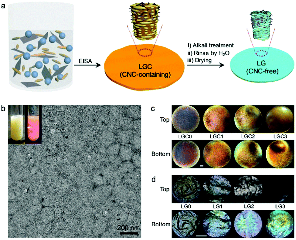 | ||
| Fig. 1 (a) Illustration of the strategy for the preparation of the latex–GO composite film. Blue: latex particles. Dark gray: GO sheets. Yellow: CNCs. (b) A typical TEM image of the aqueous dispersion of latex/GO/CNCs (LGC) with a weight ratio of 16.64:0.17:83.19. Insets are photos of the dispersion under room light (left) and irradiation of a laser (right). (c and d) Photos of the LGC (c) and LG (d) composite films. The scale bars correspond to 1 cm. Note the difference in the length of the scale bar. | ||
Preparation of latex/GO composite films
One of the shortcomings of the CNC-based films is their brittleness which greatly hinders their applications. Recent research indicated that the films could be made flexible by selectively removing CNCs through alkali treatment.18,41,42 Here, the LGC films were subjected to similar treatments (see Fig. 1a). To probe the original morphology of the film after the alkali treatment, SEM observations were carried out on a typical film with WGO = 0.17% dried from supercritical CO2 (SCCO2). Images were acquired from different places including the top and bottom surfaces as well as the fracture surface. In all the cases, highly porous structures were confirmed (Fig. 2a–c). The N2 adsorption/desorption isotherm obtained determine the macroporous features characterized by the type III adsorption isotherm with a Brunauer–Emmett–Teller (BET) surface area (S) of 190.8 m2 g−1 and an average Barrett–Joyner–Halenda (BJH) pore diameter (d) of 16 nm (Fig. 2d). Other films with different contents of GO were also checked, which revealed that the doping of GO only had limited influence on both the BET surface area and the pore diameter (Fig. S4, ESI†). | ||
| Fig. 2 (a–c) SEM images of the composite film with WGO = 0.17% after alkali treatment followed by SCCO2 drying. Images were taken at different regions of the film as indicated. The magnification of the images is the same with a scale bar of 1 μm. (d) N2 adsorption/desorption isotherm and BJH pore size distribution of the same film as in (a–c). (e) Tensile stress vs. strain curve of the film with the same composition but dried by air (i.e., LG3). The curve of LGC3 is also shown for comparison. | ||
When the films were dried in air, they shrank a lot in both thickness and size (denoted as LG0–LG3, Fig. 1d). This should be due to the collapse of the pores during air-drying.41,43 The effect of CNC removal was further checked by XRD and FTIR using the combination of LGC3/LG3 as an example. From XRD, the intensities of the peaks from CNCs at 14.8°, 16.5° and 22.8° significantly decreased (Fig. S5, ESI†). From FTIR, the peak from carbonyl at 1741 cm−1 weakened (Fig. S6, ESI†). These results unambiguously indicated that the CNCs have been successfully removed. This conclusion gained further proof from the stress–strain curves as shown in Fig. 2e where LG3 showed an elongation at break (εb) of 28%, which is much better compared to that of LGC3 (<5%).
Spectroscopic properties and internal structures
As one type of photonic crystals,44,45 the composite film derived from EISA of CNCs has a well-known chiral nematic structure which can result in the appearance of structural color.46 The interesting properties of the chiral structures make the films, either CNC-containing or CNC-free, highly attractive.47–49 From Fig. 1c, it can be seen that the LGC films are iridescent in both sides, which are indicative of the presence of ordered structures. The optical properties of the LGC films were further investigated by recording their reflection spectra on both surfaces, as shown in Fig. 3a. For the top surfaces, a red shift of the spectra was observed with increasing WGO. It is known that the wavelength corresponding to the maximum of the reflection spectrum (λmax) is determined by the helical pitch of the chiral nematic structure (p) and the averaged refractive index of the composite film (nave) following the Bragg equation (λmax = navep). As the refractive index of GO (1.314) is smaller than that of CNCs (1.504) and latex (1.567), nave will decrease with increasing WGO. Thus, the red shift of the spectra should be caused by the increase of p. The variation of the spectra on the bottom surfaces is non-monotonic. A red shift was noticed at WGO = 0.04%, after which a blue shift was observed with a further increase of WGO. A quantitative comparison between λmax from the top surface and that from the bottom one for the same film reveals an obvious mismatch. At low WGO (<0.09%), λmax on the bottom surface is slightly higher than that on the top surface while at high WGO (≥0.09%) an opposite trend was noticed with a gap of over 160 nm (Fig. S7, ESI†). The difference can also be observed by the naked eye for the LGC3 film where the top surface looks darker than the bottom one (Fig. 1c). This phenomenon became more obvious for LG films where the top surfaces totally lose iridescence (Fig. 1d). Reflection spectra of the LG films (Fig. 3b) showed that the variation of λmax with WGO basically follows the same trend as that observed for the LGC films. Comparison between λmax from the top surface and that from the bottom one revealed that λmax on the bottom surface is smaller in the whole range of WGO (Fig. S7, ESI†). Besides, all the spectra located at shorter wavelengths were compared with those from the LGC films.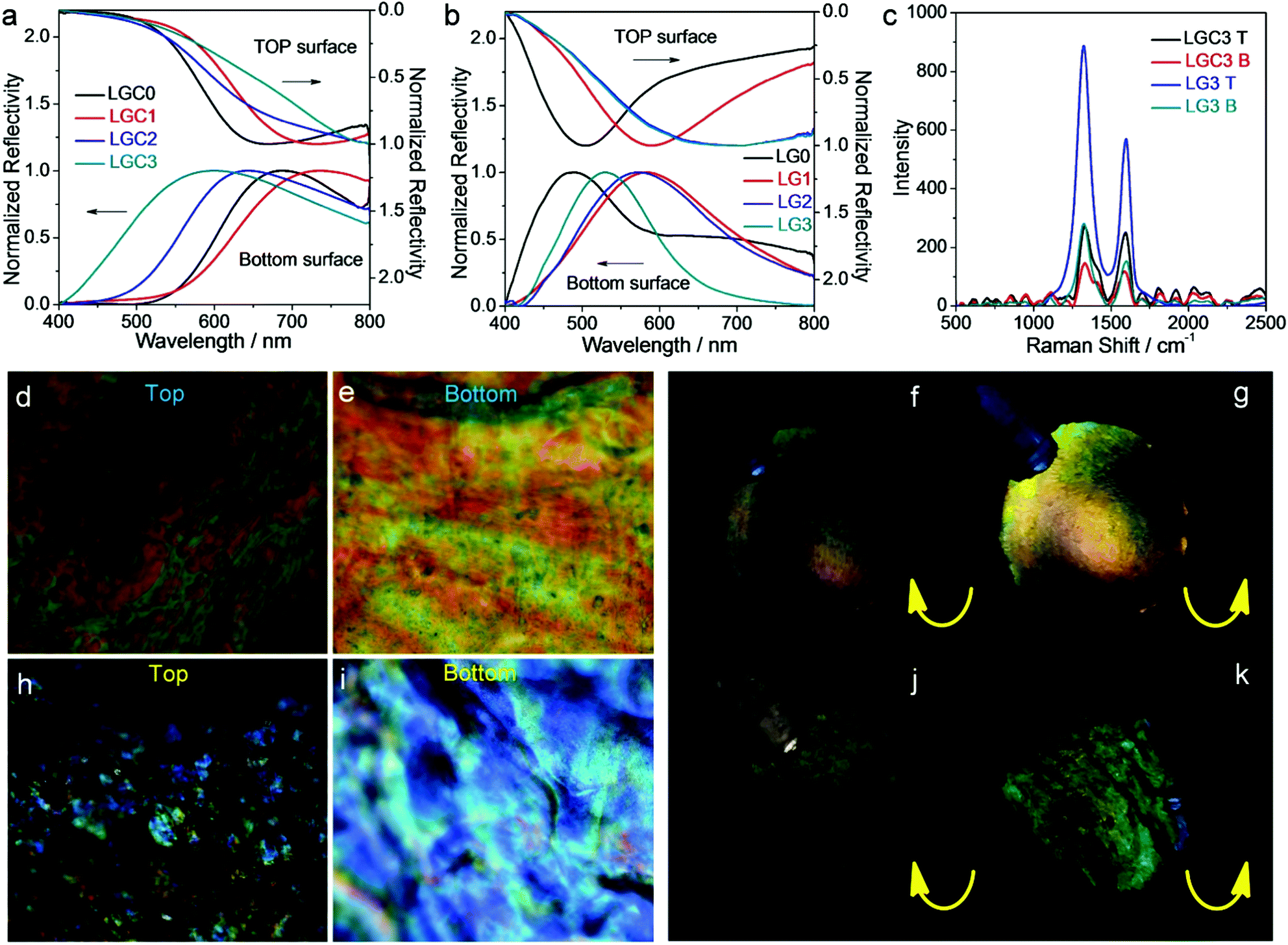 | ||
| Fig. 3 (a and b) Normalized reflection spectra of LGC (a) and LG (b) films. (c) Raman spectra of LGC3 and LG3 on top (T) and bottom (B) surfaces. (d, e, h and i) Polarized microscopy images of LGC3 (d and e) and LG3 (h and i) on the top and bottom surfaces as indicated. (f, g, j and k) Photos of LGC3 (f and g) and LG3 (j and k) taken under right-handed and left-handed circular polarizers as indicated. Recorded on the bottom surface of each film. | ||
To obtain more details, the Raman spectra of LGC3 and LG3 films were recorded, as summarized in Fig. 3c. Two peaks at 1330 cm−1 and 1598 cm−1 were detected, which correspond to a disorder-induced feature (D-band) and the E2g mode of graphite (G-band), respectively.50 For both films, the signals from the top surface are stronger than those from the bottom one, which clearly indicated that GO had an asymmetric distribution on the top and bottom surfaces. This result is consistent with the observations on the films dried by SCCO2 (Fig. 2a–c) where sheet-like structures denoted as GO were observed at the top which became hard to be found at the bottom. From Fig. 3c, one can also see that the Raman peaks from LG3 became much stronger than those from LGC3, which should be due to the improved content of GO in LG3 caused by the removal of CNCs.
POM observations were carried out on LGC3 and LG3 films. Finger-print textures were observed for LGC3 (Fig. 3d and e) and the film was more brilliant under left-handed circular polarizers than under right-handed ones (Fig. 3f and g), indicating the formation of chiral nematic structures. For LG3, the finger-print textures are not obvious and only marble-like textures were found (Fig. 3h and i). Despite these subtle changes, the film still showed obviously different appearances under left-handed and right-handed circular polarizers (Fig. 3j and k), indicating that the film also contained chiral structures. For both LGC3 and LG3 films, the textures from the top surfaces were obviously darker than the bottom ones. These observations were consistent with the results from visual inspection, reflection spectra and Raman spectra, which indicated that the compositions and/or the structural parameters of the top and bottom surfaces are different.
The structural details of the films were further examined by SEM observations on the fracture surfaces. For each film, observations were carried out on three regions locating near the top, in the middle and near the bottom, respectively. For LGC3, p values were determined to be 686, 492 and 442 nm from top to bottom (Fig. 4a–c). A similar phenomenon was found for LG3 where the values are 394, 370 and 328 nm, respectively (Fig. 4d–f). Analyses of other films give the same trend of variation in p along the normal direction (Fig. S8 and S9, ESI†). It seems that the structural parameter of the composite film, characterized by p, has a change of gradient along the normal direction, though further efforts are needed to obtain quantitative correlation. One factor causing this phenomenon could be the difference between the density of each component, i.e., latex, GO and CNCs, which leads to the gravity-induced rearrangement of the components and causes a vertical variation of each component in the film during solvent (water) evaporation. Another factor should be the so-called entropically-driven effect51–53 where GO sheets become difficult to arrange themselves in between the latex particles and CNCs, especially in the late stage of the film-forming process. It should be emphasized that the doping of GO plays an important role in creating such asymmetrically-organized composite films, as the variations of p in GO-free films are comparatively less obvious. This conclusion gained further proof from a qualitative comparison between the morphologies of the fracture surface at different regions of the same film, which shows that the top part normally suffered from phase separation or structural disorder due to the presence of a higher amount of dopant (i.e., GO). From the SEM images, it can also be seen that the p values of LG films are smaller than those of LGC ones at the same WGO, which is consistent with the results from the reflection spectra where the spectra shift to shorter wavelengths after CNCs were removed (see Fig. 3a and b).
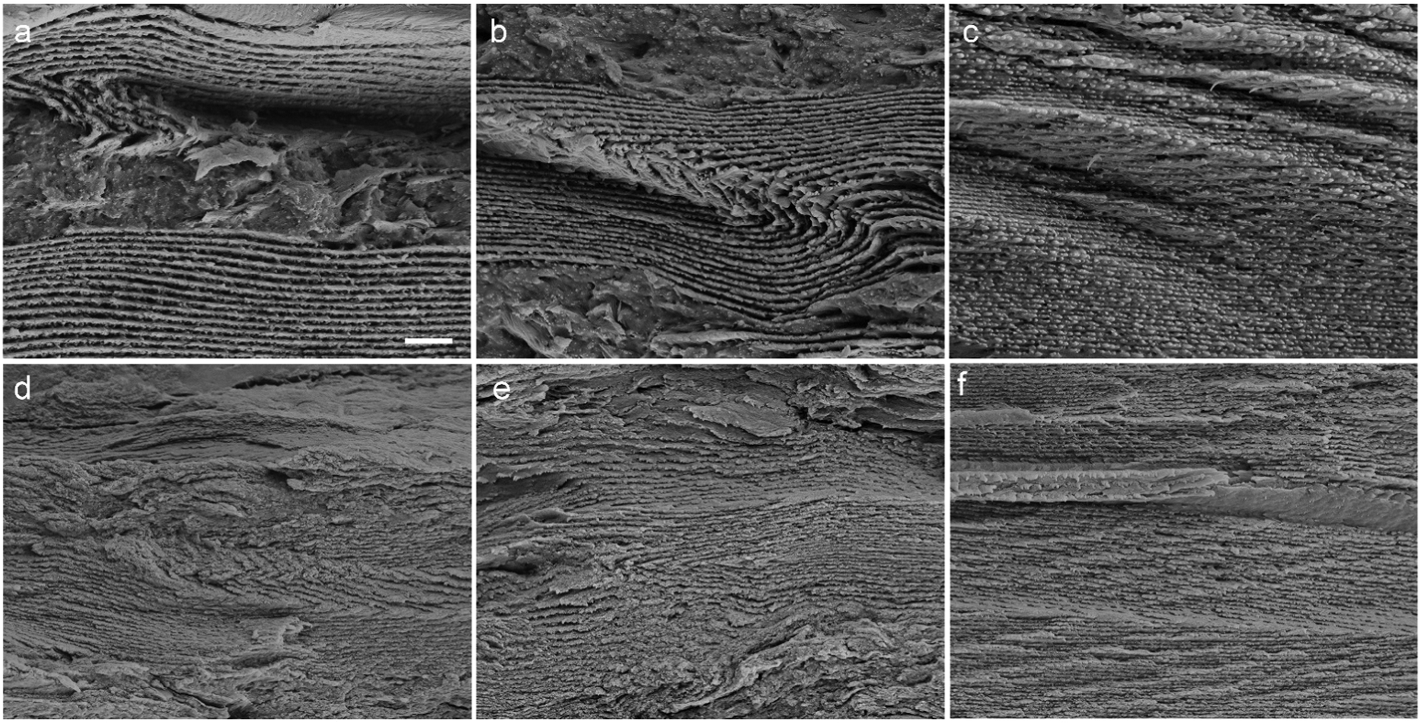 | ||
| Fig. 4 (a–c) SEM images of the fracture surface of LGC3 at regions near the top surface (a), in the middle (b) and near the bottom surface (c). (d–f) SEM images of the fracture surface of LG3 at regions near the top surface (d), in the middle (e) and near the bottom surface (f). The magnification of all the images is the same with the scale bar to be 2 μm. | ||
Synchronous response of color and actuation towards water
The asymmetric distribution of GO across the LG film imparts different wettability to the top and bottom surfaces. In addition, the good flexibility and iridescence of the film further add values to explore it as a new type of smart actuator material. The response of the LG film towards water has been demonstrated by using LG3 as a typical example. When water was dropped onto a film bar with the top surface upward using a plastic dropper, the bar began to bend toward the bottom surface after ∼15 s (Movie 1, ESI†). Within the following 1 min, the bar continuously bent with a final extent of over 180°. If water was dropped onto the bottom surface, bending of the bar still occurred with a less extent (∼135°, Movie 2, ESI†). After water was removed by filter paper, the bar could gradually recover to its original shape, indicating the reversibility of the response. This bending response can also occur for a whole circular film. When such a film was fully immersed into water (with the bottom surface upwards), the film gradually bent to the bottom surface behaving like Mimosa pudica within ∼20 s (Movie 3, ESI†). The direction of bending can also be well controlled by successively wetting the two surfaces. For example, the film would first bend to the top surface if only the bottom surface was wetted. After the top surface was also wetted, it would then bend to the bottom surface due to the larger extent of bending of the top surface (Movie 4, ESI†). As expected, continuous color change was synchronously observed during the whole process of bending.The response of the film in other solvents has also been checked. The solvents tested include ethanol (EtOH), methanol (MeOH), acetone, n-propanol (n-PrOH), n-hexane, ethyl acetate (EA), dimethyl formamide (DMF) and dimethyl sulfoxide (DMSO). No obvious actuation behavior and color change could be observed within the first 1 h. As the soaking time was extended, a gradual color change was noticed for the films in DMF and DMSO, but obvious actuation behavior occurred for the film in DMSO only after three months. For the films in other solvents, the situation remained similar to that within the first 1 h. Thus, the synchronous response of color and actuation is specific for the film in water. Though the composition and the sample preparation method are different, we suppose that the mechanism behind this phenomenon is similar to that documented for GO-based membranes.54,55 That is, the two-dimensional nanocapillaries between GO layers provide low-friction channels for water. As the nanocapillaries become narrow due to capillary forces or become clogged with water at a relatively low humidity, the membrane blocks the diffusion of other molecules.
The response of the film toward water was then quantitatively analyzed by immersing the film bar into solvent mixtures. Fig. 5a shows the photos of the film bar in a series of H2O/n-propanol (n-PrOH) mixtures with different volume percentages of H2O (VH2O%). Analysis on the soaked bars (Fig. S10, ESI†) shows a continuous increase in the extra weight fraction (Δm/m0, where Δm is the extra weight and m0 is the original weight of the film bar). The asymmetric water soaking of the film bar induced a morphological change which completed in 2–3 min. The final extent of bending scales with VH2O% is seen from the photos (Fig. 5a) and statistics on the curvature (K, Fig. 5b). Meanwhile, a continuous color change of the film bar was induced (inset of Fig. 5a). The reflection spectra of the bottom surface of the bar were recorded, which indicates a continuous red shift with increasing VH2O% (Fig. 5c and d). λmax has exceeded 800 nm in pure water, which is ∼240 nm larger than that of the dry film. Examinations were also performed using H2O/methanol (MeOH) and H2O/acetone mixtures. It was found that the variations of λmax and K are similar to those obtained from H2O/n-PrOH mixtures (Fig. 5b, d and Fig. S11, S12, ESI†).
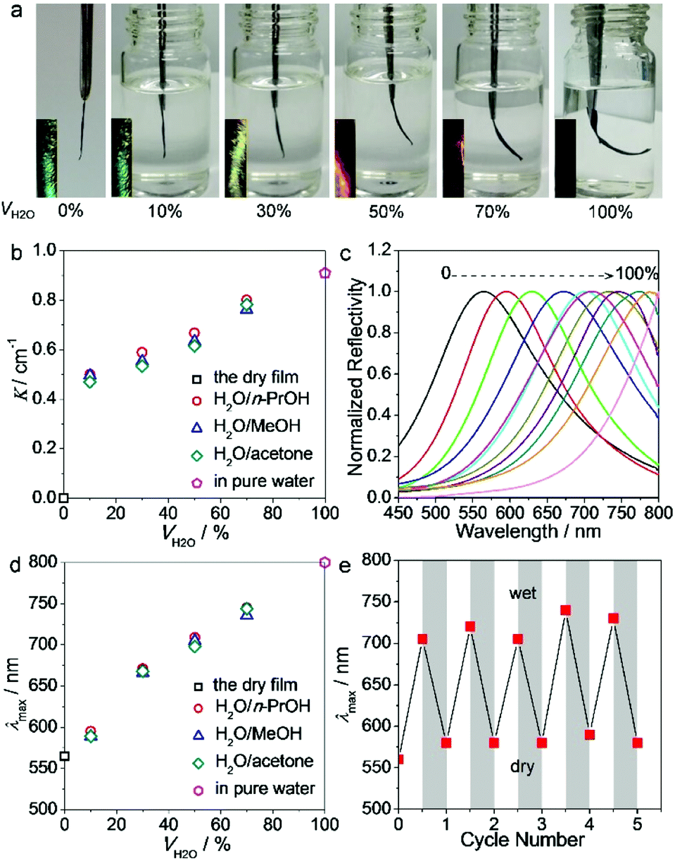 | ||
| Fig. 5 (a) Photos of the film bar of LG3 immersed in H2O/n-PrOH mixtures with varying VH2O. The photo at the bottom left corner of each sample denotes the color change of the film bar. (b) Variation of the curvature as a function of VH2O in different solvent mixtures. (c) Reflection spectra of the film bar in H2O/n-PrOH mixtures. (d) Variation of λmax as a function of VH2O in different solvent mixtures. (e) Change of λmax of the film bar by repeatedly immersing into the H2O/n-PrOH mixture with VH2O = 50%. The photos and reflection spectra of the film bar were obtained on the bottom surface. | ||
The reversibility of the morphological change was also tested by repeatedly immersing and drying the film bar in the H2O/n-PrOH mixture at VH2O% = 50%. It can be seen that the reflection spectrum of the bottom surface can be reversibly switched for at least 5 times without fatigue (Fig. 5e). For actuators with a bilayer structure, the two layers are normally weakly connected and detachment may occur during multiple uses.56 In our case, this weakness has been eliminated as the content of GO varies continuously across the whole film, accounting for the high robustness of the actuator.
Conclusions
In summary, we have developed a simple strategy to fabricate flexible latex/GO composite films with chiral nematic structure where GO has a varied distribution along the normal direction. The asymmetric distribution of GO in the film induces different wettability on the top and bottom surfaces, which impart the film a synchronous color and actuation response toward water. These characteristics make the film a new material which can be further developed into a bi-functional and visual indicator for the probe of water in various solvent mixtures. Compared to the actuators with a bilayer structure, the films presented in this work eliminate the weakly-bound interfaces between different layers, which makes the films highly robust. The strategy demonstrated here could be easily expanded to the preparation of other composite films where the components can have continuous but asymmetric distribution.Conflicts of interest
There are no conflicts to declare.Acknowledgements
This work was supported by the National Natural Science Foundation of China (No. 31570570, 31370581, and 61474124) and by the Key Research and Development Program of Shandong province China (2016GGX108002).Notes and references
- Z. Lv, Y. Luo, Y. Tang, J. Wei, Z. Zhu, X. Zhou, W. Li, Y. Zeng, W. Zhang and Y. Zhang, Adv. Mater., 2017, 30, 1704531 CrossRef PubMed.
- T. Hiratani, W. Y. Hamad and M. J. Maclachlan, Adv. Mater., 2017, 29, 1606083 CrossRef PubMed.
- H. Zheng, W. Li, W. Li, X. Wang, Z. Tang, S. X. Zhang and Y. Xu, Adv. Mater., 2018, 30, 1705948 CrossRef PubMed.
- B. Frka-Petesic, G. Guidetti, G. Kamita and S. Vignolini, Adv. Mater., 2017, 29, 1701469 CrossRef PubMed.
- X. Wang, C. Yao, F. Wang and Z. Li, Small, 2017, 13, 1702240 CrossRef PubMed.
- E. Lizundia, T. D. Nguyen, J. L. Vilas, W. Y. Hamad and M. J. Maclachlan, J. Mater. Chem. A, 2017, 5, 19184–19194 RSC.
- F. Livolant and A. Leforestier, Prog. Polym. Sci., 1996, 21, 1115–1164 CrossRef CAS.
- G. Oster, J. Gen. Physiol., 1950, 33, 445–473 CrossRef CAS.
- J.-F. Revol and R. Marchessault, Int. J. Biol. Macromol., 1993, 15, 329–335 CrossRef CAS.
- A. Espinha, G. Guidetti, M. C. Serrano, B. Frka-Petesic, A. G. M. Dumanli, W. Y. Hamad, Á. Blanco, C. López and S. Vignolini, ACS Appl. Mater. Interfaces, 2016, 8, 31935–31940 CrossRef CAS PubMed.
- M. Giese, L. K. Blusch, M. K. Khan, W. Y. Hamad and M. J. MacLachlan, Angew. Chem., Int. Ed., 2014, 53, 8880–8884 CrossRef CAS PubMed.
- J. H. Zhang, S. M. Xie, M. Zhang, M. Zi, P. G. He and L. M. Yuan, Anal. Chem., 2014, 86, 9595–9602 CrossRef CAS PubMed.
- Y. Habibi, L. A. Lucia and O. J. Rojas, Chem. Rev., 2010, 110, 3479–3500 CrossRef CAS PubMed.
- Y. Bouligand, Tissue Cell, 1972, 4, 189–217 CrossRef CAS PubMed.
- M. Giese, L. K. Blusch, M. K. Khan and M. J. Maclachlan, Angew. Chem., Int. Ed., 2015, 54, 2888–2910 CrossRef CAS PubMed.
- K. E. Shopsowitz, H. Qi, W. Y. Hamad and M. J. Maclachlan, Nature, 2010, 468, 422–425 CrossRef CAS PubMed.
- K. E. Shopsowitz, A. Stahl, W. Y. Hamad and M. J. Maclachlan, Angew. Chem., 2012, 51, 6886–6890 CrossRef CAS PubMed.
- M. K. Khan, A. Bsoul, K. Walus, W. Y. Hamad and M. J. MacLachlan, Angew. Chem., Int. Ed., 2015, 54, 4304–4308 CrossRef CAS PubMed.
- T. Asefa, Angew. Chem., Int. Ed., 2012, 51, 2008–2010 CrossRef CAS PubMed.
- K. E. Shopsowitz, W. Y. Hamad and M. J. Maclachlan, Angew. Chem., 2011, 50, 10991–10995 CrossRef CAS PubMed.
- S. H. M. Mehr, M. Giese, H. Qi, K. E. Shopsowitz, W. Y. Hamad and M. J. MacLachlan, Langmuir, 2013, 29, 12579–12584 CrossRef CAS PubMed.
- Y. Huang, J. Liang and Y. Chen, J. Mater. Chem., 2012, 22, 3671–3679 RSC.
- H. Cheng, Y. Hu, F. Zhao, Z. Dong, Y. Wang, N. Chen, Z. Zhang and L. Qu, Adv. Mater., 2014, 26, 2909–2913 CrossRef CAS PubMed.
- Y. Tai, T. K. Bera, G. Lubineau and Z. Yang, J. Mater. Chem. C, 2017, 5, 3848–3854 RSC.
- D. Martella, S. Nocentini, D. Nuzhdin, C. Parmeggiani and D. S. Wiersma, Adv. Mater., 2017, 29, 1704047 CrossRef PubMed.
- P. Brochu and Q. Pei, Macromol. Rapid Commun., 2010, 31, 10–36 CrossRef CAS PubMed.
- H. Arazoe, D. Miyajima, K. Akaike, F. Araoka, E. Sato, T. Hikima, M. Kawamoto and T. Aida, Nat. Mater., 2016, 15, 1084–1089 CrossRef CAS PubMed.
- K. Chen, Q. Fu, S. Ye and J. Ge, Adv. Funct. Mater., 2017, 27, 1702825 CrossRef.
- R. Pelrine, R. Kornbluh, Q. Pei and J. Joseph, Science, 2000, 287, 836–839 CrossRef CAS.
- M. K. Khan, W. Y. Hamad and M. J. Maclachlan, Adv. Mater., 2014, 26, 2323–2328 CrossRef CAS PubMed.
- D. D. Han, Y. L. Zhang, Y. Liu, Y. Q. Liu, H. B. Jiang, B. Han, X. Y. Fu, H. Ding, H. L. Xu and H. B. Sun, Adv. Funct. Mater., 2015, 25, 4548–4557 CrossRef CAS.
- H. Lee, T. K. Choi, Y. B. Lee, H. R. Cho, R. Ghaffari, L. Wang, H. J. Choi, T. D. Chung, N. Lu and T. Hyeon, Nat. Nanotechnol., 2016, 11, 566–572 CrossRef CAS PubMed.
- P. Xiao, N. Yi, T. Zhang, Y. Huang, H. Chang, Y. Yang, Y. Zhou and Y. Chen, Adv. Sci., 2016, 3, 1500438 CrossRef PubMed.
- M. Sabzi, M. Babaahmadi, N. Samadi, G. R. Mahdavinia, M. Keramati and N. Nikfarjam, Polym. Int., 2017, 66, 665–671 CrossRef CAS.
- H. Cheng, Y. Huang, G. Shi, L. Jiang and L. Qu, Acc. Chem. Res., 2017, 50, 1663–1671 CrossRef CAS PubMed.
- H. Cheng, F. Zhao, J. Xue, G. Shi, L. Jiang and L. Qu, ACS Nano, 2016, 10, 9529–9535 CrossRef CAS PubMed.
- M. Muralidharan, K. Shinu and A. Seema, Carbohydr. Polym., 2016, 144, 115–121 CrossRef PubMed.
- Q. Chen, P. Liu, C. Sheng, L. Zhou, Y. Duan and J. Zhang, RSC Adv., 2014, 4, 39301–39304 RSC.
- F. Nan, Q. Chen, P. Liu, S. Nagarajan, Y. Duan and J. Zhang, RSC Adv., 2016, 6, 93673–93679 RSC.
- N. Pal, P. Dubey, P. Gopinath and K. Pal, Int. J. Biol. Macromol., 2017, 95, 94–105 CrossRef CAS PubMed.
- M. K. Khan, M. Giese, M. Yu, J. A. Kelly, W. Y. Hamad and M. J. MacLachlan, Angew. Chem., Int. Ed., 2013, 52, 8921–8924 CrossRef CAS PubMed.
- J. Kelly, C. P. Manchee, S. Cheng, J. Ahn, K. Shopsowitz, W. Hamad and M. Maclachlan, J. Mater. Chem. C, 2014, 2, 5093–5097 RSC.
- J. Leng, G. Li, X. Ji, Z. Yuan, Y. Fu, H. Li, M. Qin and H. Moehwald, J. Mater. Chem. C, 2018, 6, 2396–2406 RSC.
- M. Mitov, E. Nouvet and N. Dessaud, Eur. Phys. J. E: Soft Matter Biol. Phys., 2004, 15, 413–419 CrossRef CAS PubMed.
- M. Spengler, R. Y. Dong, C. A. Michal, W. Y. Hamad, M. J. MacLachlan and M. Giese, Adv. Funct. Mater., 2018, 1800207 CrossRef.
- H. Wan, X. Li, L. Zhang, X. Li, P. Liu, Z. Jiang and Z.-Z. Yu, ACS Appl. Mater. Interfaces, 2018, 10, 5918–5925 CrossRef CAS PubMed.
- A. Nitti, A. Pacini and D. Pasini, Nanomaterials, 2017, 7, 167–189 CrossRef PubMed.
- M. Agnes, A. Nitti, D. A. Vander Griend, D. Dondi, D. Merlia and D. Pasini, Chem. Commun., 2016, 52, 11492–11495 RSC.
- M. Caricato, A. Delforge, D. Bonifazi, D. Dondi, A. Mazzantid and D. Pasini, Org. Biomol. Chem., 2015, 13, 3593–3601 RSC.
- K. Shahzadi, X. Zhang, I. Mohsin, X. Ge, Y. Jiang, H. Peng, H. Liu, H. Li and X. Mu, ACS Nano, 2017, 11, 5717–5725 CrossRef CAS PubMed.
- A. Żywociński, A. Korda, J. Gosk, S. A. Wieczorek, A. Wilk and R. Hołyst, J. Am. Chem. Soc., 2007, 129, 13398–13399 CrossRef PubMed.
- X. Xin, G. Xu, T. Zhao, Y. Zhu, X. Shi, H. Gong and Z. Zhang, J. Phys. Chem. C, 2008, 112, 16377–16384 CrossRef CAS.
- X. Xin, H. Li, S. A. Wieczorek, T. Szymborski, E. Kalwarczyk, N. Ziebacz, E. Gorecka, D. Pociecha and R. Hozyst, Langmuir, 2010, 26, 3562–3568 CrossRef CAS PubMed.
- X. Yu, H. Cheng, M. Zhang, Y. Zhao, L. Qu and G. Shi, Nat. Rev. Mater., 2017, 2, 17046 CrossRef CAS.
- R. R. Nair, H. A. Wu, P. N. Jayaram, I. V. Grigorieva and A. K. Geim, Science, 2012, 335, 442–444 CrossRef CAS PubMed.
- E. W. H. Jager, E. Smela and O. Inganäs, Science, 2000, 290, 1540–1545 CrossRef CAS PubMed.
Footnote |
| † Electronic supplementary information (ESI) available: Photos of aqueous dispersions of latex, CNCs and GO; TEM image of GO; N2 adsorption/desorption of the films dried by SCCO2; XRD, FTIR and SEM images of the films; statistics of the reflection spectra; variation in extra weight fraction; and photos of the films immersed in different solvent mixtures. See DOI: 10.1039/c8tc04319a |
| This journal is © The Royal Society of Chemistry 2019 |