
 Open Access Article
 This Open Access Article is licensed under a Creative Commons Attribution-Non Commercial 3.0 Unported Licence
Asymmetric multifunctional 3D cell microenvironments by capillary force assembly†
Qimeng
Song
,
Sergey I.
Druzhinin
 and
Holger
Schönherr
*
and
Holger
Schönherr
*
Physical Chemistry I and Research Center of Micro and Nanochemistry and Engineering (Cμ), Department of Chemistry and Biology, University of Siegen, Adolf-Reichwein-Str. 2, 57076, Siegen, Germany. E-mail: schoenherr@chemie.uni-siegen.de
First published on 30th April 2019
Abstract
The fabrication and characterization of advanced 3D cell culture microenvironments that enable systematic structure–property relationship studies are reported. The asymmetric multifunctional 3D cell microenvironments were obtained by capillary force-assisted assembly of microscale cubes at the water/air interface. The identical wettability of distinctly different microcubes, which exhibit different surface chemical functionalities or topographic nanostructures, drives the self-assembly into close-packed hexagonal aggregates with randomly arranged cubes. Hence with a library of a limited number of building blocks a very large number of distinct microenvironments with a unique trigonal pyramidal structure can be obtained in a combinatorial manner. The introduction of selective adsorption functionalities and initiator moieties for surface-initiated atom transfer radical polymerization (SI-ATRP), respectively, facilitated the immobilization of proteins such as fibronectin, and the grafting of passivating poly(acrylamide) (PAAm) brushes via SI-ATRP on selected side walls of the microwells. Thereby protein adsorption and protein mediated cell attachment was demonstrated to be varied according to the (a)symmetry of the 3D microenvironment. The random assembly of different cubes from a library comprising microcubes that are pre-functionalized or surface-structured exclusively on their top surface opens a pathway to generate a multitude of different microenvironments in a massively parallel combinatorial manner, enabling future systematic structure–property relationship studies with cells.
Introduction
The understanding of the interaction of cells with the extracellular matrix (ECM) as well as with artificial microenvironments, such as implant materials or scaffolds in tissue engineering applications, is of central importance to be able to control cell behavior.1 It is long established that cells sense and respond to external cues, which include the nature, density and spacing of adhesion peptides,2 surface structure on various length scales3 and mechanical properties of the matrix.4 In response to changes in matrix and substrate stiffness, altered mechanical properties of molecular tethers of peptides affording focal adhesions5 and stress-stiffening of surrounding hydrogels,6 cells respond by altering of focal adhesions as well as by changes in morphology, migration, proliferation, apoptosis or differentiation. On a biomolecular level the mechanical factors are translated into variations in cell signaling and concomitantly gene expression.7In this context, the fabrication of 3D microwells for systematic cell-environment studies has garnered significant attention after evidence has been reported that cell behavior, e.g. in terms of adhesion, differentiation, and apoptosis, but also susceptibility to drugs, differs substantially on flat 2D surfaces versus 3D microwells.8In vivo cells are surrounded in 3D by the ECM, which is a complex fibrillar matrix with characteristic variations in chemical composition and physical properties.9 By contrast, conventional in vitro 2D cell culture substrates (e.g. tissue culture polystyrene, TCPS) are flat and rigid. Therefore, more realistic 3D microenvironments with tailored properties are of considerable importance. However, except for a number of examples,10 it has been so far a challenge to interrogate specifically the role of individual physical parameters on cell behavior, because of the concomitant change of other chemical and/or physical parameters, when one parameter was changed. To implement this in versatile 3D microenvironments with full control has been difficult or even impossible to date.
One main challenge is to engineer 3D microenvironments with spatially controlled, yet decoupled chemical and mechanical signals.10 For fabrication of simple 3D microwells a number of photolithography techniques have been applied,11 but also soft lithography, including embossing12 and micro molding in capillaries (MIMIC).13 Sidewall nanopatterning and functionalization combined independently with nanostructuring represents likely an unsurmountable challenge for all projection-based lithography methods. Serial write procedures offer more flexibility, but are hardly scalable.14
More recently, the so-called “TopoWellPlate”, which provides a huge library of topographies for cell–surface interaction studies, was designed by de Boer and coworkers.15 This combinatorial multiwell format allowed them to identify uniquely defined bioactive surface topographies, which induce a wide variety of cellular morphologies in bone marrow derived human mesenchymal stem cells.
It is clear that current micro- and nanofabrication approaches do not allow one to increase the complexity of designed 3D microwells to be able to study the interaction of individual or few cells with a fully engineered surrounding in a systematic manner.14 To overcome the shortcomings of established projection-based approaches, which inherently possess their limitations in the fabrication of complex asymmetric microcompartments, in which all these parameters are varied independently, a self-assembly route was recently proposed.16 In this approach prefabricated microcubes, which have been functionalized on their top side, e.g. by soft lithography or imprinting, are assembled at the water/air interface by capillary force assembly into ordered aggregates. This process is controlled by the wettability of the cubes faces and leads for hydrophobic microcubes (static water contact angle θ > 100°) to close-packed hexagonal aggregates that can be transferred to and fixed on a solid support. The aggregates comprise distinct microenvironments with a unique trigonal pyramidal structure that are composed by three individual cubes. The assembly strategy is motivated by the plethora of work on colloid and nanocrystal assembly,17 which has been expanded to millimeter-scale objects and cell laden microgel building blocks by Whitesides and coworkers18 and by Khademhosseini and coworkers, respectively.19
Here we expand on our previous work on polymer building blocks for the fabrication of designed cell microenvironments by guided assembly20 and interfacial self-assembly.16 The introduction of versatile polymer brushes10a,21 for controlling the interfacial functionality as well as surface topographic nanostructuring was explored to obtain asymmetric multifunctional 3D cell microenvironments in a combinatorial fashion and to study details of protein adsorption as well as the feasibility of interrogating the interaction of pancreatic tumor cells with the multitude of microenvironments fabricated.
Experimental section
The materials and the standard experimental procedures used in this work were adapted from previously published work.16,20,22Modification of the cubes’ top surfaces with nanoline patterns
Polystyrene (PS) cubes were fabricated by Nano Imprint Lithography (NIL) (Eitre 3, Obducat, Sweden), as reported before.16,20,22 Nanoscale line patterns with a pitch of 750 nm were imprinted on top of the cubes using a nanopatterned hard-poly(dimethylsiloxane) (h-PDMS) stamp.23 This second NIL step was carried out for 60 s using a temperature of 105 °C and a pressure of 3 bars. The PDMS stamp was peeled off after the temperature cooled down to 75 °C. The topography of the nanopatterned cube surface was examined with a MFP-3D Bio (Asylum Research, Santa Barbara, USA) atomic force microscope (AFM). Intermittent contact (tapping) mode images were acquired at 256 pixels × 256 pixels over scan sizes of 5 μm × 5 μm with MLCT-D cantilevers (Bruker, Santa Barbara, USA) at ambient conditions.Fabrication of fluorescence dye labelled cubes
To distinguish differently surface modified cubes with fluorescence microscopy, cubes were labelled with dyes. The dyes were mixed into the PS used for cube fabrication by NIL. Cubes labelled with red dyes were fabricated by dissolving Sudan III (85%, Sigma Aldrich, Germany) or Nile red (≥98%, Roth, Germany) in solutions of PS in toluene with a concentration of 10 mg mL−1 and 0.5 mg mL−1, respectively. For fabrication of green cubes, fluorescein (95%, Merck, Germany) was firstly dissolved in ethanol (0.5 mg mL−1), and then mixed with a solution of PS in toluene (5 v/v%). The cubes labelled with fluorescein will show green and the cubes without dye labelling will appear black under the fluorescence microscope. The cubes labelled with Nile red appear yellow, if the red and green channels are superimposed in widefield fluorescence microscopy, due to the wide excitation range of Nile red.Self-assembly of microcubes with different components
For assembly of microwells with two different types of hydrophobized cubes, unlabeled cubes and 1-octadecanethiol/16-mercaptohexadecanoic acid (ODT/MHDA) modified cubes (labelled with Nile red) were mixed in ratios of ∼3![[thin space (1/6-em)]](https://www.rsc.org/images/entities/char_2009.gif) :1, 1:1 and 1:2 and were subsequently dispersed at the water/air interface. The amount of cubes was controlled by controlling the area from which the cubes were released from the imprinted arrays on the substrate. For assembly of microwells with three different types of hydrophobized cubes, unlabeled cubes, ODT/MHDA modified cubes (Nile red labelled) and ODT/ω-mercaptoundecyl bromoisobutyrate (MUBiB) modified cubes (fluorescein labelled) were mixed in a ratio of ∼2:3:2 and were subsequently dispersed at the water/air interface.
:1, 1:1 and 1:2 and were subsequently dispersed at the water/air interface. The amount of cubes was controlled by controlling the area from which the cubes were released from the imprinted arrays on the substrate. For assembly of microwells with three different types of hydrophobized cubes, unlabeled cubes, ODT/MHDA modified cubes (Nile red labelled) and ODT/ω-mercaptoundecyl bromoisobutyrate (MUBiB) modified cubes (fluorescein labelled) were mixed in a ratio of ∼2:3:2 and were subsequently dispersed at the water/air interface.
Fixation of cube aggregates and surface functionalization with PAAm
A pre-cleaned glass substrate was placed under the assembled aggregates inside of water. After completely evaporating the water at ambient conditions, the aggregates composed of differently chemically functionalized cubes (unfunctionalized PS or gold-coated cubes functionalized on 5 sides with self-assembled monolayers (SAMs)) of ODT/MHDA were sitting on the glass substrate. The aggregates were then fixed onto the support by a heat treatment on a hot plate (150 °C) for 10 min. Afterwards, the substrates were rinsed with ethanol, followed by immersion into 1 mM solution of the initiator MUBiB in absolute ethanol (![[greater than or equal, slant]](https://www.rsc.org/images/entities/char_2a7e.gif) 99.8%, VWR, Germany) overnight at ambient temperature. With this, Au coated 5 sides of the cubes were modified with MUBiB. The substrates were rinsed with ethanol and Milli-Q water before use.
99.8%, VWR, Germany) overnight at ambient temperature. With this, Au coated 5 sides of the cubes were modified with MUBiB. The substrates were rinsed with ethanol and Milli-Q water before use.
To graft PAAm brushes on the MUBiB-covered cube faces, methanol (28 mL), Milli-Q water (12 mL), acrylamide (AAm, 3 g) and N,N,N′,N′′,N′′-pentamethyldiethylenetriamine (PMDETA, 0.56 mL) were stirred in a round bottom flask under argon flow for 15 min, followed by the addition of 128 mg Cu(I)Br, synthesized according to the literature.24 The reaction solution was transferred via a syringe into a homebuilt glass reactor, which contained the glass substrates carrying the cube aggregates and for reference measurements two Au coated glass slides (2 nm Cr, 80 nm Au) also modified with a SAMs of MUBiB. The polymerization was allowed to proceed under argon for 30 min. Before use, the substrates were rinsed with ethanol and Milli-Q water.
Protein adsorption in microwells
Protein adsorption tests were carried out for 1 h by immersing the substrate, which contained close-packed hexagonal aggregates of PS cubes or a mixture of PS and PAAm modified cubes into a 1 mg mL−1 phosphate-buffered saline (PBS) solution of Bovine serum albumin (BSA, 95.0%, Sigma-Aldrich, Germany). After washing with PBS, the BSA adsorbed to the surface was labelled with fluorescein 5(6)-isothiocyanate (FITC, ≥90%, Sigma Aldrich, Germany) by immersing the sample into a solution of the dye in PBS (0.1 mg mL−1) for 1 h. Samples were taken out from the FITC solution and rinsed with PBS before fluorescence microscopy analysis. Widefield fluorescence microscopy images were acquired by using a fluorescence microscope (Axiovert 135, Carl Zeiss, Oberkochen, Germany).Confocal laser scanning microscopy (CLSM) imaging
The fluorescence CLSM set-up comprises an inverted frame Olympus IX-71 (Olympus, Hamburg, Germany), PicoQuant (Berlin, Germany) Microtime 200 main optical unit and pulsed diode laser (LDHD-C-485, 55 ps pulse width, 485 nm emission wavelength, 20 MHz repetition rate). The sample was excited and its fluorescence was collected by a Zeiss LD Achroplan 40×/0.60 objective (Carl Zeiss GmbH, Jena, Germany), separated from the excitation light by a dichroic mirror (z500dcxr, Chroma, Bellows Falls, USA) and a filter (HQ510lp, Chroma, Bellows Falls, USA). The fluorescence was detected through 50 μm pinhole by a Single-Photon Avalanche Diode (PD1CTC, Micro Photon Devices, Bolzano, Italy). The fluorescence images of PS cube aggregates fixed on the surface of 20 × 20 × 0.15 mm3 Menzel-Gläser borosilicate cover slips (Gerhard Menzel GmbH, Braunschweig, Germany) were recorded in a horizontal 80 × 80 μm2xy-area with 512 × 512 pixels2 resolution at the rate of 4.8 ms per pixel.Cell experiments
The culture of Patu 8988 T cells, cell seeding onto the substrates and cell immunofluorescent staining were carried out according to earlier published protocols.13c,25 Cell viability tests were performed by live dead staining. Live/dead cells were labelled with fluorescein diacetate (FDA) and propidium iodide (PI), which was carried out according to the literature.25Results and discussion
PS microcubes with ∼30 μm edge length, which are coated with a thin PDMS oligomer layer (static water contact angle θ = 102°),16 were self-assembled to close-packed hexagonal aggregates by capillary forces at the water/air interface. The hydrophobic cubes are known to be oriented preferentially with vertex up orientation.16,22 The hexapolar interface distortion results in attractive capillary forces and drives the cubes into large aggregates (Fig. 1a).26 In this orientation the cubes appear in top view photographs with a hexagonal shape (Fig. 1b). In the close-packed hexagonal aggregates, each cube is strongly supported by six neighboring cubes, which may explain why the aggregates maintained their structure even after being transferred from the water surface to a solid support. The transferred aggregates of cubes with vertex up orientation are also recognized in the scanning electron microscopy (SEM) images shown in Fig. 1c. In addition, one may note the formation of a unique 3D microwell built up by three contacting individual cubes (see inset and schematic in Fig. 1c and d). The size of each microwell is controlled by the size of the individual cubes. For example, since the edge length of the cubes used in this work was a = 30 μm, the hexagonal projected area of the microwell will be 1560 μm2 and the volume of the microwell 4500 μm3 (Fig. 1d).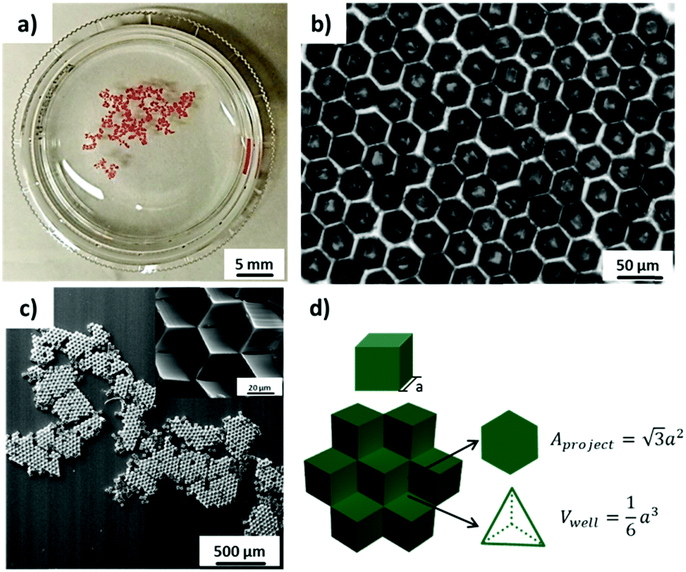 | ||
| Fig. 1 (a) and (b) Optical microscopy images of self-assembled cube aggregates (θ = 102°) with close-packed hexagonal structure at the water/air interface. (c) SEM images of close-packed hexagonal cube aggregates fixed thermally on a glass substrate after transfer (the inset shows the structure at high magnification). (d) Scheme of the trigonal pyramidal microwells, which were formed by three individual cubes with vertex up orientation in close-packed hexagonal aggregates; a is the length of the cube edge. | ||
The orientation and capillary interactions of microcubes with a water contact angle of ∼102° only depend on the wettability of the cubes’ surfaces.16 In addition, cubes with different surface chemical compositions could also assemble into close-packed hexagonal aggregates, provided that they possess identical wettability. Here we compared as-prepared hydrophobized PS cubes and cubes that were decorated on 5 faces with Au/binary SAMs of ODT/MHDA or ODT (mole fraction XODT = 0.8) and MHDA (XMHDA = 0.2), respectively.16 The binary SAMs were assembled to ensure to within the experimental error identical static water contact angles of θ = 102 ± 1°. To be able to distinguish among the different types of cubes, PS cubes labelled with the fluorophore Nile Red were used to fabricate cubes functionalized with ODT/MHDA after covering with a semi-transparent layer of Au (thickness ∼25 nm).
It was observed from the fluorescence microscopy images (Fig. 2a and b) that cubes with different surface chemical properties self-assembled randomly into close-packed hexagonal aggregate based on capillary interactions. Black (non-dye labelled) cubes represent the hydrophobized PS cubes and red cubes are the Au-ODT/MHDA functionalized cubes.
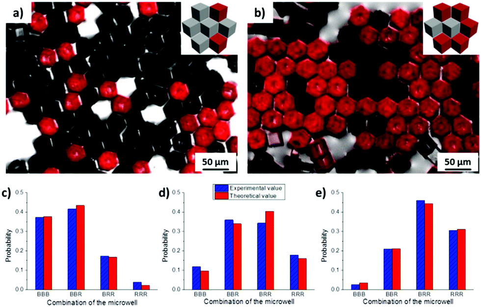 | ||
| Fig. 2 (a and b) Widefield fluorescence microscopy images of close-packed hexagonal aggregates, which contained two distinct cube species at the water/air interface: black and red, with initial number ratios of (a) ∼2:1 and (b) 1:2. Black cubes (B): non-labelled hydrophobized PS cubes, red cubes (R): Nile red-labelled ODT/MHDA modified cubes. The insets show schematics of the cube orientation and the aggregates formed (top view). Statistical analysis of microwells formed by three neighboring cubes with initial number ratios of (c) Nblack:Nred ≈ 3:1, (d) Nblack:Nred ≈ 1:1, (e) Nblack:Nred ≈ 1:2. More than 700 microwells were analysed for each aggregate of different cubes ratio. | ||
By mixing cubes with different surface functionalities but identical wettability, microwells containing different surface properties could thus be generated. All four expected types of microwells were formed by mixing non-functionalized cubes (black, B) and Au-ODT/MHDA functionalized cubes (red, R), namely BBB, BBR, BRR and RRR. The probability of each microwell changed gradually with the initial ratio of non-modified and Au-ODT/MHDA modified cubes which added to the water/air interface, for instance Nblack:Nred ≈ 3:1, 1:1 and 1:2. The higher this initial B/R ratio of a particular surface functionalized cube in the mixture was, the higher was the probability of finding microwells, with high B/R ratio. Moreover, the probability obtained from statistical analysis for each microwell was in good agreement with the theoretical value, which indicated that different cubes were distributed inside of the aggregate in a random manner.
In order to introduce versatile functionalities onto selected microwell faces,10a polymer brushes were synthesized by grafting AAm from a SAMs containing the initiator MUBiB by SI-ATRP. The requirement for this polymerization is the introduction of the initiator thiol into a hydrophobic SAMs. Close-packed hexagonal aggregates of cubes functionalized with a binary SAMs of ODT/MUBiB (χODT = 0.2, XMUBiB = 0.8, θ = 102°) were thus assembled at the water/air interface (Fig. 3).
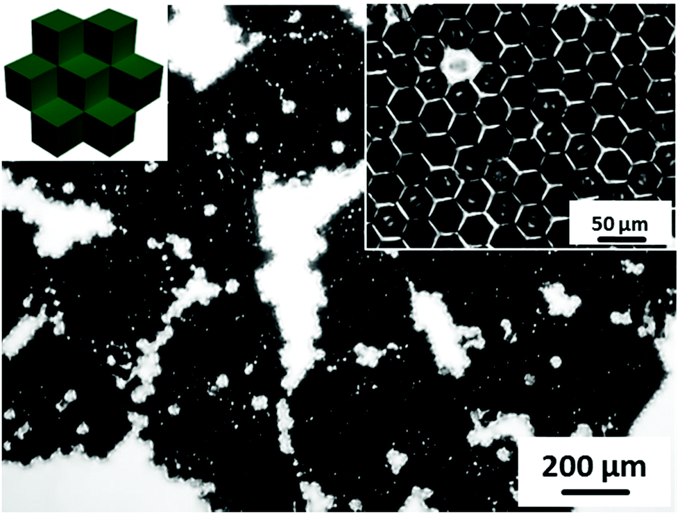 | ||
| Fig. 3 Optical microscopy image of close-packed hexagonal aggregates self-assembled from ODT/MUBiB functionalized cubes (χODT = 0.2) at the water/air interface. The inset shows a higher magnification view of one aggregate. | ||
In order to design 3D microwell arrays with multiple surface functionalities, three different types of cubes were fabricated: (1) hydrophobized PS cubes (black, B), (2) PS cubes functionalized with Au/binary SAMs of ODT/MHDA (XODT = 0.8, XMHDA = 0.2) (yellow, Y), and (3) PS cubes functionalized with Au/binary SAMs of ODT/initiator MUBiB (XODT = 0.2, XMUBiB = 0.8) (green, G). The cubes (2) and (3) were labelled with Nile red and fluorescein, respectively, to be able to identify them in widefield fluorescence microscopy images (Fig. 4). All three types of cubes were found in the aggregates, irrespective of their surface chemical composition. The identical surface wettability with θ = 102° drove the cubes into the self-assembled close-packed hexagonal aggregates, in which the colored cubes were randomly distributed within the aggregates, underlining that microwells with multiple surface chemical properties were obtained successfully.
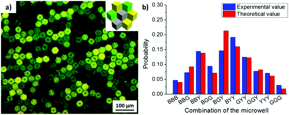 | ||
| Fig. 4 (a) Wide-field fluorescence microscopy image of close-packed hexagonal aggregates at the water/air interface formed from three distinct cube species with θ = 102°: black cubes (B, unlabelled hydrophobized PS cubes), yellow cubes (Y, labelled with Nile Red, surface: ODT/MHDA), and green cubes (G, labelled with fluorescein, surface: ODT/MUBiB). The inset shows a schematic of a multicomponent cube aggregate (top view). (b) Statistical analysis of microwells formed by three neighboring cubes. The number ratio of the three distinct cube species dispersed at the water/air interface was Nblack:Nyellow:Ngreen ≈ 2:3:2. More than 500 microwells were analyzed. | ||
The number of the possible microwell combinations N depends on the number of cube species and can be calculated by the following equation:16
 | (1) |
For example, with 2 cube species, 4 combinations of microwells could be obtained (Fig. 2), while with 3 cube species, already 10 different combinations listed in Fig. 4 were obtained. With a statistical analyses of microwell combinations of more than 500 microwells at initial cubes ratio of Nblack:Nyellow:Ngreen ≈ 2:3:2, the probability of each combination was in a good agreement with the theoretical result for random mixing (Fig. 4b). Furthermore, the probability of each microwell combination could be tuned with the initial ratio of each cube species added to the water/air interface. For instance, when the initial ratio of ODT/MHDA functionalized cubes (Y) become major in the mixture, the type of microwell containing ODT/MHDA sides (BBY, BGY, BYY, GYY, GGY, YYY) was observed more frequently than the other combinations.
In order to fabricate microwells with varying topographic cues, PS microcubes were modified with nanoline patterns with a pitch of 750 nm on the top surface via the NIL. The SEM image in Fig. 5a confirmed that the top surfaces of the microcubes were modified with nanoline patterns and that the cubes were only marginally deformed. In addition, the orientation of the patterns was controlled by the relative orientation of the PDMS stamp with respect to the cubes. AFM imaging confirmed the pitch (750 ± 28 nm) and the depth (21 ± 2 nm) of the line pattern (Fig. S2, ESI†). Furthermore, the wettability of the structured surface was to within the experimental error unaffected (θ = 103 ± 1°) (Fig. S3, ESI†), probably due to the limited depth of the trenches.27 Intact cubes with the line pattern could also be released from the substrate and could be self-assembled at the water/air interface. It was observed from sets of SEM images (Fig. 5d–f) that microwells with trigonal pyramidal structure were formed successfully and that microwells with one, two or three patterned faces pointing into the well interior. Compared to the bottom surface, which is pure PS (θ = 90°), the top surface is more hydrophobic, therefore, more than 75% of cubes were observed, based on the statistical analysis of more than 500 cubes, with the patterned sides above the water/air interface (Fig. S4, ESI†). This is in a good agreement with the result observed in our previous study.16
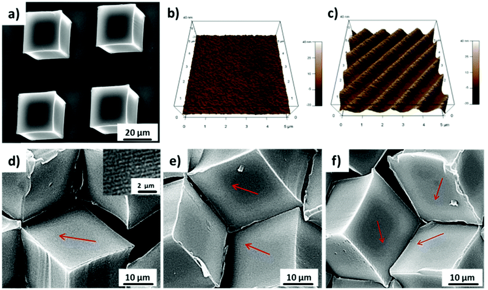 | ||
| Fig. 5 (a) SEM image of PS microcubes modified by NIL on the top surface with a nanoline pattern. (b and c) AFM height images of an intact (b) and NIL-patterned (c) microcube top surfaces. (d)–(f) SEM images of microwells, which were self-assembled using nanoline patterned PS microcubes at the water/air interface with (d) one face, (e) two faces and (f) three faces comprising the nanoline pattern inside the well. The inset shows a higher magnification view of the nanoline pattern; the arrows indicate the direction of the NIL-lines. | ||
To study the behavior of cells confined within 3D microwells exposing multiple functionalities, brushes were grafted onto the inner walls of the microwells. PAAm brushes are a well-established long-term stable passivating coating.10a,21 Multifunctional microwells were thus fabricated by capillary force-assisted assembly and SI-ATRP (Scheme 1). In particular, close-packed hexagonal aggregates were formed at the water/air interface with two distinct types of cube species with θ = 102°: hydrophobized PS cubes and Au-ODT/MHDA modified cubes. Afterwards, the aggregates were transferred to a glass surface by evaporating the water and thermal fixing by using a hot plate (150 °C for 10 min). Due to the strong support from six neighboring cubes, the aggregates retained with their close-packed hexagonal structure after transfer and fixation (Fig. 6a). The Au covered cubes faces were subsequently refunctionalized with a SAMs of the initiator MUBiB (the original SAMs were thermally desorbed after the heat treatment),28 and passivating PAAm brushes were grown exclusively from the MUBiB modified surfaces via SI-ATRP.
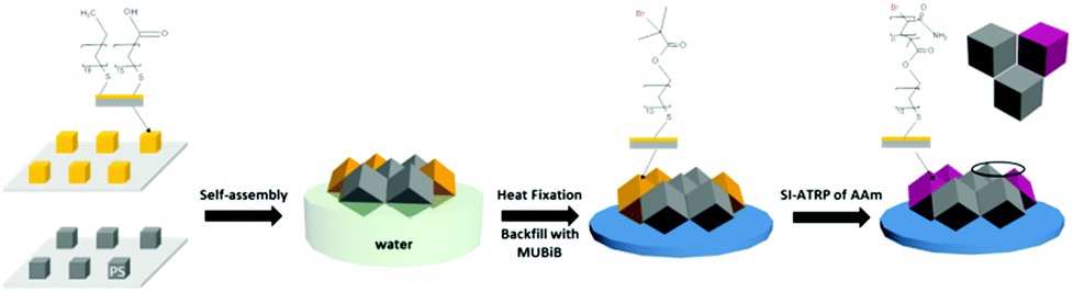 | ||
| Scheme 1 Fabrication of 3D microwells containing multiple differently functionalized surfaces (protein resistant: PAAm; protein attractive: PS) via self-assembly of different microcubes at the water/air interface. | ||
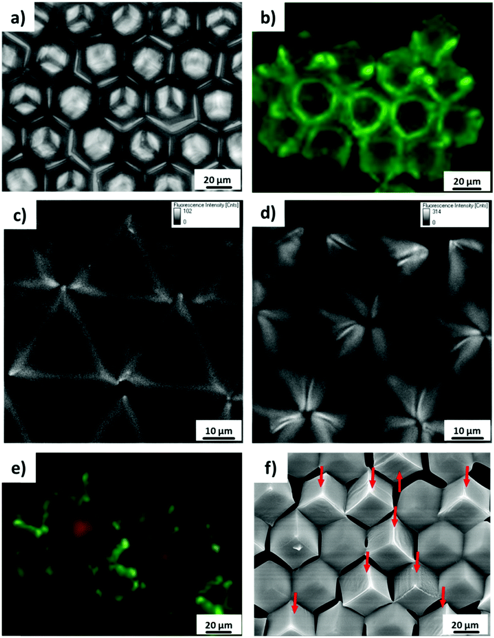 | ||
| Fig. 6 (a) Optical microscopy image of close-packed hexagonal PS cube aggregate fixed on solid glass substrate. (b) Widefield fluorescence microscopy image and (c and d) confocal microscopy sections of close-packed microcube aggregates after adsorption of BSA labelled with FITC, imaged at a focal plane position 8 μm (c) and 22 μm (d) above the cover slip. (e) Widefield fluorescence microscopy image of BSA that was adsorbed on cube aggregates (labelled post adsorption with FITC), which contain different components: non-functionalized (green) and PAAm functionalized PS cubes (red, Sudan III labelled). (f) SEM image of cube aggregates of protein adsorption (from cell culture medium); the aggregate contains different components: non-functionalized and PAAm functionalized PS (pointed out with red arrows) cubes. | ||
To distinguish the passivated and non-passivated cubes faces in the assembled, protein adsorption tests were carried out. The fluorescence microscopy images in Fig. 6 show that BSA labelled with FITC is adsorbed onto the non-passivated hydrophobized PS cube surfaces. By contrast, when the Au-covered cubes in the hexagonal aggregates were functionalized with passivating PAAm brushes, an asymmetric microwell with various chemical properties was generated (Fig. 6e and f). Face-selective protein adsorption onto the walls of the microwells was observed. Clearly, BSA did not adsorb to walls, which were modified with PAAm (red cubes), but adsorbed onto PS walls (Fig. 6e). In addition, the same protein adsorption behaviour was observed in SEM measurements after immersing the asymmetric multifunctional microwells into cell culture medium for 1 h (Fig. 6f). Pronounced differences in protein adsorption between PAAm modified cubes surfaces (clear surface) and non-modified surface (blurry surface) were observed clearly. Proteins from the cell culture medium only adsorbed to the cubes, which had not been functionalized with PAAm brushes, in good agreement with the fluorescence microscopy data (Fig. 6e). 3D microwells with four different combinations were formed with non-modified and PAAm modified cubes, namely microwell containing three, two, one, and zero passivating PAAm surfaces (the red arrow points to the cubes, whose surfaces were functionalized with PAAm).
Subsequently, the behavior of human pancreatic tumor (Patu 8988T) cells in microwells, which exposed single or multiple surface properties, was analyzed in a feasibility study. In particular, wells exposing MHDA or PS and PAAm brushes (in all possible combinations) were used. Cells were also seeded on planar substrates functionalized with MHDA and PAAm brushes, as controls. To enhance cell attachment, the samples were pre-incubated in a fibronectin (FN) solution (10 μg mL−1 in PBS) at room temperature for 60 min. No cells are attached to the PAAm brushes surfaces,13c,21 while by contrast, cells attached well on MHDA modified surfaces and on the positive control i.e. TCPS (Fig. S5, ESI†). These observations are in full agreement with previous reports.13c,21
The viability of adhering cells was investigated via a live–dead assay. FN-coated hydrophobized PS surface were observed to show no negative effect on cell viability. No dead cells were observed after 24 h incubation on TCPS or glass substrates that supported PS microwells, based on live–dead stain/fluorescence microscopy analysis (Fig. S6a and b, ESI†). After 72 h incubation, proliferating cells covered the entire surface of the cube aggregates and less than 0.5% of the observed cells were dead (Fig. S6c, ESI†). This result indicates that the cells remained viable in the microwells, which is further corroborated by time lapse imaging, in which cells are observed to probe their local microenvironment (see Video S1, ESI†).
By tuning the cell density during the seeding process, the initial number of cells per microwell could be controlled. At low cell seeding density, cells were located individually within a given microwell, while at high cell seeding density, the cells in adjacent microwells will communicate (Fig. S7, ESI†), which is also observed in conventional microwell array systems.11e One or two (possibly due to proliferation) pancreatic tumor cells (Patu 8988T) were observed to attach in the 3D microwells, which is also recognized in SEM images (Fig. 7b and c). Compared to cells on flat MHDA surfaces, which showed a larger spreading area, cells confined within the microwell presented the smaller projected spreading areas. In addition, cells were observed not only to attach to one side, but all three sides of the microwell by extending their filopodia. Similar cell behavior was also observed in conventional microwells and also microwells obtained by guided assembled.13c,20
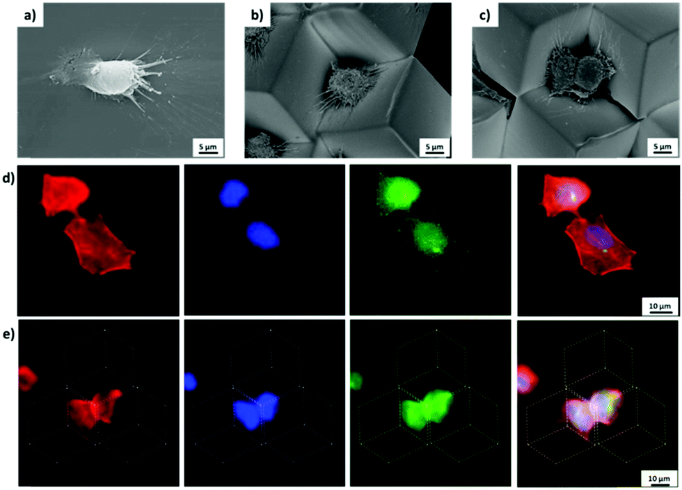 | ||
| Fig. 7 (a)–(c) SEM images of Patu 8988T cell cultured on (a) MHDA modified flat substrate; (b) and (c) in microwells. (d and e) Widefield fluorescence microscopy images of Patu 8988T cell (d) on MHDA modified flat substrate and (e) in MHDA modified microwells. Cells were fixed for SEM measurements and stained for actin (red), paxillin (green), and nuclei (blue) after 24 h incubation. The dashed lines indicate the position of the microcubes as a guide to the eye. | ||
The intracellular structures were investigated in more detail by immunostaining actin, paxillin and the nuclei of cells cultured on flat substrates and in microwells. Cells spreading on flat 2D surface showed bundles of actin microfilaments after 24 h incubation, which were visualized after staining with rhodamine conjugated phalloidin by fluorescence image Fig. 7d. The microfilaments were observed to be oriented along the long axis of the cells, which is in full agreement with the observations by Lilge et al.29 By contrast, cells trapped in 3D microwells were observed with smaller projected spreading area, as also observed by SEM (Fig. 7b and c). Moreover, in the microwells, microfilaments were observed to be oriented to the center of the well, likely because of the trigonal pyramidal structure (Fig. 7e). Although the positions of the focal adhesions are hardly observed in the fluorescence microscopy images, the attachment of filopodia to the well were clearly observed in the SEM images.
Finally, exemplary multifunctional 3D cell microwells were fabricated. With two different functionalized surfaces involved in the microwells, hydrophobized PS and PAAm, according to eqn (1), four different combinations were obtained (Fig. 8a). In particular, these microwells contain three PAAm side walls, two PAAm side walls and one hydrophobized PS side wall, one PAAm side wall and two hydrophobized PS side walls and three hydrophobized PS side walls. In these asymmetric and symmetric multifunctional microwells the attachment of individual cells was studied with Patu 8988T cell after 24 h incubation. The cells were observed to attach and spread exclusively on the FN-primed PS side walls, but not on the passivating PAAm side walls (Fig. 8). For instance, in microwells, which contained two PAAm side walls and one hydrophobized PS side wall, cells only attached and spread in 2D on one FN-primed PS side wall (Fig. 8b). In the microwells, which contained two and three hydrophobized PS side wall, the cell were observed to extend their body to two and three different walls, respectively, to attach to all the FN-coated walls (Fig. 8c and d). This observation indicates that the human pancreatic tumor cells attached selectively to certain surfaces in the 3D environment and adjusted their shape to fit various environments even in a small compartment. In addition, no cells were observed in microwells, which only contained PAAm modified surfaces, due to the anti-fouling of PAAm.13c,21
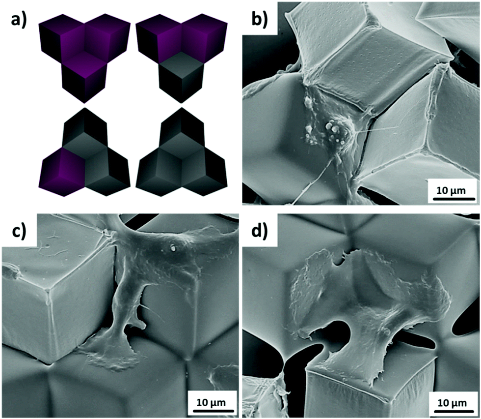 | ||
| Fig. 8 (a) Scheme of the microwells with four different combinations of local microenvironments. The hydrophobized PS cubes and PAAm functionalized cubes are shown in grey and violet, respectively. (b)–(d) SEM images of fixed Patu 8988T cells attached inside of microwells contained (b) two, (c) one, (d) zero PAAm modified surfaces, respectively. | ||
These data underpin that cells can be successfully cultivated in these microwells for extended period of time, that they remain viable and proliferate. The different surface functionalities positioned in a predetermined manner in space afford unique microcompartments, whereby the random assembly of different pre-functionalized or top surface-structured cubes opens a pathway to obtain a multitude of different microenvironments in a massively parallel combinatorial manner. This platform thus enables future systematic structure–property relationship studies with cells, focusing at the analysis of individual cells in the different microcompartments.
Conclusions
A new strategy for the fabrication of asymmetric multifunctional microenvironments was established based on capillary force-assisted assembly of hydrophobic microscale cubes. Owing to the identical wettability of distinctly different microcubes, which exhibit different surface chemical functionalities or topographic nanostructures, close-packed hexagonal aggregates were self-assembled at the water/air interface. Passivating PAAm brushes were synthesized on selected side walls of the trigonal pyramidal microwells via SI-ATRP. Thereby protein adsorption and protein mediated cell attachment were observed in a feasibility study to vary in a pre-determined manner depending on chemical symmetry of the microenvironment. The random assembly of different pre-functionalized or top surface-structured cubes opens a pathway to generate a multitude of different microenvironments in a massively parallel combinatorial manner, enabling future systematic structure–property relationship studies with cells.Conflicts of interest
There are no conflicts to declare.Acknowledgements
The authors thank Dipl.-Biol. Sabine Wenderhold-Reeb and Dipl.-Ing. Gregor Schulte for their expert biological and technical support and Dr Daniel Wesner, MSc Qasim F. M. Alhusaini for help with AFM and SEM measurements. We thank MSc Zhiyuan Jia for valuable discussions. We are indebted to Dr Jürgen Schnekenburger (Biomedical Technology Center of the Medical Faculty Münster, Germany) for kindly providing the cell line. Part of this work was performed at the Micro- and Nanoanalytics Facility (MNaF) of the University of Siegen. The authors acknowledge the European Research Council (Grant No. 279202), the Deutsche Forschungsgemeinschaft (Grant No. INST 221/87-1FUGG), and the University of Siegen for financial support.Notes and references
- Y. Farouz, Y. Chen, A. Terzic and P. Menasché, Stem Cells, 2015, 33, 1021–1035 CrossRef CAS PubMed.
- (a) A. S. Rowlands, P. A. George and J. J. Cooper-White, Am. J. Physiol.: Cell Physiol., 2008, 295, C1037–C1044 CrossRef CAS PubMed; (b) A. Chopra, V. Lin, A. McCollough, S. Atzet, G. D. Prestwich, A. S. Wechsler, M. E. Murray, S. A. Oake, J. Y. Kresh and P. A. Janmey, J. Biomech., 2012, 45, 824–831 CrossRef PubMed; (c) E. A. Cavalcanti-Adam, A. Micoulet, J. Blümmel, J. Auernheimer, H. Kessler and J. P. Spatz, Eur. J. Cell Biol., 2006, 85, 219–224 CrossRef CAS PubMed; (d) S. P. Massia and J. A. Hubbell, J. Cell Biol., 1991, 114, 1089–1100 CrossRef CAS PubMed.
- (a) M. Arnold, E. A. Cavalcanti-Adam, R. Glass, J. Blümmel, W. Eck, M. Kantlehner, H. Kessler and J. P. Spatz, Chem. Phys. Chem., 2004, 5, 383–388 CrossRef CAS PubMed; (b) C. J. Bettinger, R. Langer and J. T. Borenstein, Angew. Chem., Int. Ed., 2009, 48, 5406–5415 ( Angew. Chem. , 2009 , 121 , 5512–5522 ) CrossRef CAS PubMed; (c) K. Chung, J. A. Dequach and K. L. Christman, Nano LIFE, 2010, 1, 63–77 CrossRef CAS PubMed; (d) D. Ning, B. Duong, G. Thomas, Y. Qiao, L. Ma, Q. Wen and M. Su, Langmuir, 2016, 32, 2718–2723 CrossRef CAS PubMed.
- (a) D. E. Discher, P. A. Janmey and Y.-L. Wang, Science, 2005, 310, 1139–1143 CrossRef CAS PubMed; (b) B. Geiger, J. P. Spatz and A. D. Bershadsky, Nat. Rev. Mol. Cell Biol., 2009, 10, 21–33 CrossRef CAS PubMed; (c) D. E. Ingber, FASEB J., 2006, 20, 811–827 CrossRef CAS PubMed; (d) S. Schmidt, M. Zeiser, T. Hellweg, C. Duschl, A. Fery and H. Möhwald, Adv. Funct. Mater., 2010, 20, 3235–3243 CrossRef CAS.
- B. Trappmann, J. E. Gautrot, J. T. Connelly, D. G. T. Strange, Y. Li, M. L. Oyen, M. A. Cohen Stuart, H. Boehm, B. Li and V. Vogel, et al. , Nat. Mater., 2012, 11, 642–649 CrossRef CAS PubMed.
- R. K. Das, V. Gocheva, R. Hammink, O. F. Zouani and A. E. Rowan, Nat. Mater., 2016, 15, 318–325 CrossRef CAS PubMed.
- (a) F. Guilak, D. M. Cohen, B. T. Estes, J. M. Gimble, W. Liedtke and C. S. Chen, Cell Stem Cell, 2009, 5, 17–26 CrossRef CAS PubMed; (b) D. E. Discher, D. J. Mooney and P. W. Zandstra, Science, 2009, 324, 1673–1677 CrossRef CAS PubMed; (c) P. A. Janmey and R. T. Miller, J. Cell Sci., 2011, 124, 9–18 CrossRef CAS PubMed; (d) J. Thiele, Y. Ma, S. M. C. Bruekers, S. Ma and W. T. S. Huck, Adv. Mater., 2014, 26, 125–147 CrossRef CAS PubMed; (e) A. K. Patel, M. W. Tibbitt, A. D. Celiz, M. C. Davies, R. Langer, C. Denning, M. R. Alexander and D. G. Anderson, Curr. Opin. Solid State Mater. Sci., 2016, 20, 202–211 CrossRef CAS.
- (a) V. Vogel and M. Sheetz, Nat. Rev. Mol. Cell Biol., 2006, 7, 265–275 CrossRef CAS PubMed; (b) E. Cukierman, R. Pankov and K. M. Yamada, Curr. Opin. Cell Biol., 2002, 14, 633–640 CrossRef CAS.
- J. K. Mouw, G. Ou and V. M. Weaver, Nat. Rev. Mol. Cell Biol., 2014, 15, 771–785 CrossRef CAS PubMed.
- (a) I. Lilge and H. Schönherr, Angew. Chem., Int. Ed., 2016, 55, 13114–13117 CrossRef CAS PubMed; (b) S. J. Kim, H. R. Cho, K. W. Cho, S. Qiao, J. S. Rhim, M. Soh, T. Kim, M. K. Choi, C. Choi and I. Park, et al. , ACS Nano, 2015, 9, 2677–2688 CrossRef CAS PubMed; (c) S. Sprio, E. Campodoni, M. Sandri, L. Preti, T. Keppler, F. A. Müller, N. M. Pugno and A. Tampieri, Int. J. Mol. Sci., 2018, 19, 3604 CrossRef PubMed.
- (a) A. Revzin, K. Sekine, A. Sin, R. G. Tompkins and M. Toner, Lab Chip, 2005, 5, 30–37 RSC; (b) M. Ochsner, M. R. Dusseiller, H. M. Grandin, S. Luna-Morris, M. Textor, V. Vogel and M. L. Smith, Lab Chip, 2007, 7, 1074–1077 RSC; (c) B. D. Carlo and L. P. Lee, Anal. Chem., 2006, 78, 7918–7925 CrossRef PubMed; (d) J. R. Rettig and A. Folch, Anal. Chem., 2005, 77, 5628–5634 CrossRef CAS PubMed; (e) M. Håkanson, M. Textor and M. Charnley, Integr. Biol., 2011, 3, 31–38 CrossRef PubMed; (f) M. Charnley, M. Textor, A. Khademhosseini and M. P. Lutolf, Integr. Biol., 2009, 1, 625–634 CrossRef CAS PubMed.
- (a) S. Kobel, M. Limacher, S. Gobaa, T. Laroche and M. P. Lutolf, Langmuir, 2009, 25, 8774–8779 CrossRef CAS PubMed; (b) M. R. Dusseiller, D. Schlaepfer, M. Koch, R. Kroschewski and M. Textor, Biomaterials, 2005, 26, 5917–5925 CrossRef CAS PubMed.
- (a) H.-W. Shim, J.-H. Lee, T.-S. Hwang, Y. W. Rhee, Y. M. Bae, J. S. Choi, J. Han and C.-S. Lee, Biosens. Bioelectron., 2007, 22, 3188–3195 CrossRef CAS PubMed; (b) A.-K. Marel, S. Rappl, A. Piera Alberola and J. O. Rädler, Macromol. Biosci., 2013, 13, 595–602 CrossRef CAS PubMed; (c) I. Lilge, S. Jiang and H. Schönherr, Macromol. Biosci., 2017, 17, 1600451 CrossRef PubMed.
- P. Li, X. Dou and H. Schönherr, Polym. Int., 2019, 26, 42001 Search PubMed.
- (a) N. R. M. Beijer, A. S. Vasilevich, B. Pilavci, R. K. Truckenmüller, Y. Zhao, S. Singh, B. J. Papenburg and J. de Boer, Adv. Biosyst., 2017, 1, 1700002 CrossRef; (b) A. Reimer, A. Vasilevich, F. Hulshof, P. Viswanathan, C. A. van Blitterswijk, J. de Boer and F. M. Watt, Sci. Rep., 2016, 6, 18948 CrossRef CAS PubMed.
- Q. Song, M. Steuber, S. I. Druzhinin and H. Schönherr, Angew. Chem., Int. Ed., 2019, 58, 5246–5250 CrossRef CAS PubMed.
- (a) M. A. Wood, J. R. Soc., Interface, 2007, 4, 1–17 CrossRef CAS PubMed; (b) C.-W. Kuo, J.-Y. Shiu, Y.-H. Cho and P. Chen, Adv. Mater., 2003, 15, 1065–1068 CrossRef CAS; (c) J. Wang, G. Duan, Y. Li, G. Liu and W. Cai, ACS Appl. Mater. Interfaces, 2014, 6, 9207–9213 CrossRef CAS PubMed; (d) S. Kim, A. N. Mitropoulos, J. D. Spitzberg, H. Tao, D. L. Kaplan and F. G. Omenetto, Nat. Photonics, 2012, 6, 818–823 CrossRef CAS; (e) B. Yu, H. Cong, Z. Yang, S. Yang, Y. Wang, F. Zhai and Y. Wang, Materials, 2017, 10(9), 1035 CrossRef PubMed; (f) B. Ai and Y. Zhao, Nanophotonics, 2019, 8, 1–26 CAS; (g) W. H. Evers, B. Goris, S. Bals, M. Casavola, J. de Graaf, R. van Roij, M. Dijkstra and D. Vanmaekelbergh, Nano Lett., 2013, 13(6), 2317–2323 CrossRef CAS PubMed; (h) M. P. Boneschanscher, W. H. Evers, J. J. Geuchies, T. Altantzis, B. Goris, F. T. Rabouw, S. A. P. van Rossum, H. S. J. van der Zant, L. D. A. Siebbeles and G. van Tendeloo, et al. , Science, 2014, 344, 1377–1380 CrossRef CAS PubMed; (i) Y. H. Lee, W. Shi, H. K. Lee, R. Jiang, I. Y. Phang, Y. Cui, L. Isa, Y. Yang, J. Wang, S. Li and X. Y. Ling, Nat. Commun., 2015, 6, 6990 CrossRef CAS PubMed; (j) Y. Yang, Y. H. Lee, I. Y. Phang, R. Jiang, H. Y. F. Sim, J. Wang and X. Y. Ling, Nano Lett., 2016, 16, 3872–3878 CrossRef CAS PubMed; (k) Y. Yang, Y. H. Lee, C. L. Lay and X. Y. Ling, Chem. Mater., 2017, 29, 6137–6144 CrossRef CAS.
- (a) N. Bowden, A. Terfort, J. Carbeck and G. M. Whitesides, Science, 1997, 276, 233–235 CrossRef CAS PubMed; (b) N. Bowden, I. S. Choi, B. A. Grzybowski and G. M. Whitesides, J. Am. Chem. Soc., 1999, 121, 5373–5391 CrossRef CAS; (c) C. Mao, V. R. Thalladi, D. B. Wolfe, S. Whitesides and G. M. Whitesides, J. Am. Chem. Soc., 2002, 124, 14508–14509 CrossRef CAS PubMed; (d) D. B. Wolfe, A. Snead, C. Mao, N. B. Bowden and G. M. Whitesides, Langmuir, 2003, 19, 2206–2214 CrossRef CAS.
- (a) Y. Du, E. Lo, S. Ali and A. Khademhosseini, Proc. Natl. Acad. Sci. U. S. A., 2008, 105, 9522–9527 CrossRef CAS PubMed; (b) J. Yeh, Y. Ling, J. M. Karp, J. Gantz, A. Chandawarkar, G. Eng, J. Blumling, R. Langer and A. Khademhosseini, Biomaterials, 2006, 27, 5391–5398 CrossRef CAS PubMed.
- M. Steuber and H. Schönherr, Eur. Polym. J., 2019, 113, 47–51 CrossRef CAS.
- I. Lilge and H. Schönherr, Langmuir, 2016, 32, 838–847 CrossRef CAS PubMed.
- Q. Song and H. Schönherr, Langmuir, 2019 DOI:10.1021/acs.langmuir.9b00792.
- H. Schmid and B. Michel, Macromolecules, 2000, 33, 3042–3049 CrossRef CAS.
- H. Ma, J. Hyun, P. Stiller and A. Chilkoti, Adv. Mater., 2004, 16, 338–341 CrossRef CAS.
- (a) S. Jiang, B. Lyu, M. Müller, D. Wesner and H. Schönherr, Langmuir, 2018, 34, 14670–14677 CrossRef CAS PubMed; (b) Y. Voß, E. Wassel, S. Jiang, Q. Song, S. I. Druzhinin and H. Schönherr, Macromol. Biosci., 2017, 17, 1600337 CrossRef PubMed.
- (a) G. Morris, S. J. Neethling and J. J. Cilliers, Miner. Eng., 2010, 23, 979–984 CrossRef CAS; (b) G. Soligno, M. Dijkstra and R. van Roij, Phys. Rev. Lett., 2016, 116, 258001 CrossRef PubMed; (c) G. Soligno, M. Dijkstra and R. van Roij, Soft Matter, 2017, 14, 42–60 RSC.
- K. Y. Suh and S. Jon, Langmuir, 2005, 21, 6836–6841 CrossRef CAS PubMed.
- H. Schönherr, H. Ringsdorf, M. Jaschke, H.-J. Butt, E. Bamberg, H. Allinson and S. D. Evans, Langmuir, 1996, 12, 3898–3904 CrossRef.
- I. Lilge, S. Jiang, D. Wesner and H. Schönherr, ACS Appl. Mater. Interfaces, 2016, 8, 23591–23603 CrossRef CAS PubMed.
Footnote |
| † Electronic supplementary information (ESI) available. See DOI: 10.1039/c9tb00653b |
| This journal is © The Royal Society of Chemistry 2019 |