 Open Access Article
Creative Commons Attribution 3.0 Unported Licence
Optimization of anodic porous transport electrodes for proton exchange membrane water electrolyzers
Melanie
Bühler
ab,
Friedemann
Hegge
bc,
Peter
Holzapfel
c,
Markus
Bierling
c,
Michel
Suermann
 d,
Severin
Vierrath
 abe and
Simon
Thiele
 *cf
*cf
aHahn-Schickard Institute, Georges-Koehler-Allee 103, 79110 Freiburg, Germany. E-mail: melanie.buehler@hahn-schickard.de; Tel: +49 76120354061
bLaboratory for MEMS Applications, IMTEK Department of Microsystems Engineering, University of Freiburg, Georges-Koehler-Allee 103, 79110 Freiburg, Germany
cForschungszentrum Jülich GmbH, Helmholtz Institute Erlangen-Nürnberg for Renewable Energy (IEK-11), Egerlandstr. 3, 91058 Erlangen, Germany. E-mail: si.thiele@fz-juelich.de
dInstitute of Electric Power Systems, Leibniz Universität Hannover, Appelstr. 9A, 30167 Hannover, Germany
eFIT – Freiburg Center for Interactive Materials and Bioinspired Technologies, Georges-Koehler Allee 105, 79110 Freiburg, Germany
fDepartment of Chemical and Biological Engineering, Friedrich-Alexander-Universität Erlangen-Nürnberg, Egerlandstr. 3, 91058 Erlangen, Germany
First published on 20th November 2019
Abstract
In this study we investigate the potential of porous transport electrode (PTE) based membrane electrode assemblies (MEAs) for proton exchange membrane water electrolysis. The focus is on the overpotential determining anodic PTE for the oxygen evolution reaction. The influences of catalyst loading, ionomer content and porous titanium substrate on the polarization behavior are analyzed. The comparison of a porous fiber-sintered substrate with a powder-sintered substrate shows no significant differences in the kinetic and mass transport regions. Ohmic losses, however, are lower for fiber PTEs above a catalyst loading of 1.0 mgIrO2 cm−2. Variations of the Nafion content in the catalyst layer reveal changes of mass transport and ohmic losses and have an influence on the reproducibility. Varying the noble metal loading and therefore the thickness of the applied catalyst layer influences the kinetic region and ohmic resistance of the MEAs. The best compromise between reproducibility and performance is found for a loading of 1.4 mgIrO2 cm−2 and 9 wt% Nafion. The stable operation of the aforementioned PTE is shown in a 200 h durability test at 2 A cm−2.
Introduction
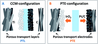
One major focus of current research for proton exchange membrane water electrolysis (PEMWE) is the reduction of noble metal loadings while maintaining or even prolonging durability. Due to the fast reaction kinetics of the hydrogen evolution reaction (HER), the platinum loading at the cathode can be reduced to several μg cm−2 without significantly affecting the performance.1 This also applies to the sluggish oxygen evolution reaction (OER) when using advanced anode catalysts based on IrOx nanoparticles or nanowires with low loadings in the range of 0.08–0.1 mgIrO2 cm−2.2,3 The development of novel catalysts for the rate limiting OER is therefore a central measure to eliminate limitations associated with the large-scale implementation of PEMWEs at the GW per year scale, as iridium is only mined as a secondary metal and is ten times scarcer than platinum.4 One approach to further reduce the noble metal loading that has not yet been fully investigated is the development of novel designs for the membrane electrode assembly (MEA) addressing the electrode–membrane interface as previously investigated for PEM fuel cells (PEMFCs).5PEMWE MEA-configurations are currently restricted to the CCM-configuration only (Fig. 1A). Here a CCM is sandwiched between porous transport layers (PTLs) made of titanium, to meet the durability conditions at the anode,6 and carbon PTLs at the cathode side. Sandwiching a membrane in-between the cathodic PTE (cPTE) and anodic PTE (aPTE), as shown in Fig. 1B, will be named as PTE-configuration in the following. The PTE-configuration could be a promising alternative to the standard CCM-configuration, but is not yet commercially available.
The challenging electrode side for implementing the PTE-configurations is not the cathode, where usually the same cPTEs as those in PEMFCs are used. The cPTEs are available as porous carbon cloth or paper substrates with or without an additional microporous layer (MPL), hydrophobic treatment and with various Pt/C loadings.7 Anodic PTEs, however, consisting of porous titanium substrates coated with an iridium-based catalyst for the OER are not commercially available. One reason might be the costly and challenging fabrication of customized sintered titanium substrates for depositing the iridium-based catalyst layer on top. Even small variations of sintering process parameters like pressure and temperature can lead to cracks or bending of the substrates. The rapid formation of an oxide layer at the surface of the titanium structures increases the electric interfacial contact resistances, and impurities in the gas atmosphere during sintering can cause mechanical instability.8 Currently available porous titanium substrates were initially developed e.g. for industrial filter applications and have not yet been optimized for PEMWE. Since also titanium-based MPLs for smoothening the titanium substrates9 are still at a research level, the subsequent deposition of smooth catalyst layers on top of the coarse titanium substrate is not trivial either.
Despite the challenging fabrication of aPTEs for PEMWE, there are some studies on novel anode electrode designs available in the literature. Grigoriev et al. compared the performance of different powder-sintered PTLs with different porosities and therefore changed transport properties.10 Their self-made PTLs were tested either in a CCM-configuration using a Nafion 115 membrane or in a PTE-configuration. The noble metal loading of the spray coated anode was 2 mgIrblack cm−2. The PTE-configurations performed slightly worse, which was explained by a reduced direct protonic contact area between the catalyst layer and membrane compared to that in the CCM setup. Sapountzi et al. introduced a carbon paper substrate sputter-coated with titanium and subsequently 0.55 mgIrO2 cm−2. The electrode was then coated with Nafion prior to hot-pressing the compound onto a Nafion 117 membrane.11 At an optimum Nafion loading of 1.5 mgNafion cm−2 a current density of 0.9 A cm−2 was measured at 1.75 V (tested at 60 °C). The cathode electrode was coated with 1.5 mgNafion cm−2 as well, to improve the mechanical stability during and after hot pressing. Lee et al. also used a carbon paper substrate, but applied a thin IrO2 layer directly via electrodeposition without a titanium based intermediate layer.12 The highest performance was found for a loading of 0.1 mgIrO2 cm−2, with a current density of 1.92 A cm−2 at 1.8 V using a Nafion 212 membrane (tested at 90 °C). Compared to previous studies, the mass activity was significantly improved when directly depositing the iridium based catalyst on the electronically conductive carrier substrate. Besides an improved performance and reduced materials costs, the use of carbon substrates is still a critical issue, since only a small crack in the deposited layers would start a rapid corrosion process at the anode side in PEMWEs as mentioned above.6 Choe et al. went one step further and electrodeposited an iridium based catalyst layer directly on a porous titanium substrate instead of using carbon paper.13 The IrO2 layer not only acted as a catalyst but also as a corrosion-protective layer for the titanium substrate. The electrodes were tested in the PTE-configuration with a Nafion 212 membrane at 120 °C. Catalyst loadings as low as 0.4 mgIrO2 cm−2 showed a sufficiently high cell performance with a current density of 0.97 A cm−2 at 1.6 V. The stability of the electrodeposited catalyst layer was higher than that for a spray coated catalyst layer, but it can be argued that the coating had to be perfect to prevent corrosion of the porous substrate. However, with a continuous and defect-free Ir-coating, the durability of the MEAs was found to be increased due to the reduced Ti-PTL surface area exposed to the oxidative environment.
The question if and how the deposition of the anodic catalyst layer directly on top of the titanium PTL influences the long-term behavior of PTE-based MEAs extends the already intensively discussed topic regarding corrosion protective layers for PTLs. For example, Rakousky et al. found that 78% of the degradation rate during a long-term experiment originated from the degradation of the Ti-PTL.14 A protective sputter deposited platinum layer on top of the PTL reduced the degradation remarkably. Due to concerns regarding the formation of an oxide layer on the Pt-coating, Liu et al. presented a thin sputtered iridium layer on top of the titanium PTL to improve electrical resistance and long-term durability.15 Since coating the titanium PTL with a noble metal layer of Au, Pt or Ir increases the cost of PEMWEs, Bystron et al. presented an etching technique to remove the oxide layer of the titanium PTLs (reduced electric resistance) while at the same time introducing Ti hydride on the titanium surface (corrosion protective layer, reduced oxide layer formation).16 This cheap and effective alternative to expensive protective noble metal coatings improved the cell performance compared to untreated PTLs as well in terms of electrical resistance and durability. However, the degradation mechanisms and the associated need to coat Ti-PTLs are not yet fully understood. Suermann et al. demonstrated the operation of pristine PTLs in CCM configurations for several hundred hours at elevated cell voltages without significant degradation.17
In a recent publication we showed that PTE based approaches can perform just as well as or even better than CCM based approaches.18 To stimulate the further development of aPTEs for PEMWEs, there is the need to show the potential for improving the performance and reducing the fabrication costs when using the PTE-configuration instead of the standard CCM-configuration. Therefore, in this study, we focus on the optimization of spray coated aPTEs made of porous titanium substrates coated with an IrO2 and Nafion-based catalyst layer. To the best of our knowledge, no attempts to further optimize catalyst layers for aPTEs based on different commercial porous titanium substrates have been made so far. We consequently evaluated the optimum noble metal loading and ionomer content in the catalyst layers of the aPTEs as well as the influence of different titanium substrates. We furthermore showed the stable operation of the most reproducible aPTE developed in this work for 200 h at a constant current of 2 A cm−2.
Experimental
MEA
The reference CCM-configuration in this work consisted of a commercial half-sided cathode CCM (FuelCellsEtc) with 0.5 mgPt/C cm−2 (60% platinum on Vulcan) on a Nafion 117 membrane, which was spray coated with 1.4 mgIrO2 cm−2 (Alfa Aesar) and 9 wt% Nafion D520 (FuelCellStore) on the anode side. The CCM was sandwiched between a porous carbon cloth substrate (FuelCellsEtc, type GDL-CT) at the cathode and a titanium fiber PTL (Bekaert, 1 mm thick, 56% porosity) at the anode side. The geometric active area of all MEAs used in this work was 5 cm2.For the PTE-configurations, commercial carbon cloth based cPTEs (FuelCellsEtc, type SL-GDE) with a catalyst loading of 0.5 mgPt/C cm−2 (60% platinum on Vulcan) were purchased. The aPTEs were fabricated via spray coating an IrO2-based anode catalyst layer with varying noble metal and Nafion loadings on different porous titanium substrates. One PTL was the same as that used in the CCM-configuration (Bekaert, 1 mm thick, 57% porosity); the second was a titanium powder-sintered PTL (Mott, 1 mm thick, 40% porosity). Prior to deposition of the catalyst layer, burrs (residues from laser cutting) at the edges of the 5 cm2 sized titanium PTLs were removed with a scalpel. The PTLs were then immersed in an alkaline cleaning solvent (Borer Chemie, 5 vol% Deconex OP153 in DI-water) and sonicated for 10 min to remove organic contaminants. Afterwards, the PTLs were rinsed and sonicated again for 10 min in 2-propanol followed by DI-water. The aPTE and cPTE were pressed against a Nafion 117 membrane to complete the PTE-configuration.
The IrO2-based catalyst inks for spray coating the aPTEs contained 1 wt% solids (metal and Nafion D520, FuelCellsEtc) in a mixture of 2-propanol and DI-water (equal parts). After wetting the IrO2 powder with water, 2-propanol and Nafion were added. The bottle was stirred after adding a new component. The ink was then continuously ultra-sonicated in an ice bath for 30 min (Hielscher, model UIS250L, 0.55 W, 90% amplitude) and stirred at the same time. After stirring the ink overnight, the sonication step was repeated, before filling the ink into the syringe of the spray coater (Sono-Tek, model ExactaCoat). An ultrasonic nozzle type AccuMist (48 kHz) set to 5 W at a height of 37 mm was used. The titanium substrates were laser cut into 5 cm2 squares and placed in 1 mm thick PTFE frames on the hot plate of the spray coater. The hot plate was set to 120 °C, the shaping air to 0.6 kPa, the path speed to 170 mm s−1 and the flow rate to 0.45 ml min−1. The ink was stirred within the syringe during spray coating with a magnetic stirrer. A meander shaped path with a pitch of 1.5 mm was set. The additional ink for re-loading the syringe was placed on a magnetic stirrer to keep the particles in the ink well dispersed within the solvents. The noble metal loading was determined via spray coating on a 1 cm2 rectangular metal sheet, which was weighed on a microscale (Sartorius, model ME 36S). Since the catalyst material was found to partly sediment in the syringe and long tubing of the spray coater, the final Nafion content in the sprayed catalyst layers was determined via a thermogravimetric analysis (Netsch, model STA 449F5) according to the work of Feng et al.19 The TGA measurement was performed under controlled air conditions at a heating rate of 5 K min−1. The final temperature of 1000 °C was held for 1 h. The Nafion content was found to be approximately five times higher than that expected from the ink preparation. We therefore recommend TGA measurements after manufacturing to be sure about the final composition of the sprayed catalyst layers.
Electrochemical testing
A two-electrode test cell was used to study the CCM and PTE-configurations. Eight M6 screws tightened at 8.5 Nm were used to fix the cell. The screws were inserted into two aluminum end plates holding the inner cell parts, as well as the heating elements, which were set to 80 °C. The potentiostat was connected to copper plates, which were electrically insulated from the end plates with self-adhesive PTFE foil and on the other side were in contact with the titanium flow fields. The flow fields were designed with a 5 cm2 parallel finger structure to evenly distribute water towards the PTLs. The PTLs were placed within PTFE frames, which at the same time acted as hard-stops, setting the compression of the PTLs. For the titanium PTL a 1 mm thick PTFE sheet was used since the compressibility of the 1 mm thick titanium material was expected to not change significantly when being assembled in the test cell. To ensure sufficient contact of the PTEs with the membrane, a relatively high compression of 60% was chosen for the carbon cloth based cPTE via using a 150 μm thick PTFE frame. The membrane was placed between the PTLs. A relatively high internal cell resistance of around 0.091 Ω cm2 without the membrane was measured and will be addressed in future test cell design via coating the flow fields with a thin gold layer.Both electrodes were supplied separately with DI-water (Ismatec peristaltic pump, model IP 65) at a flow rate of 40 ml min−1. The tubing at the inlets of the test cell was placed in a water bath (Lauda, model Ecoline 003) to preheat the incoming water. The temperature, which was measured at three different points, was monitored at the anodic water inlet and outlet, as well as directly in the titanium flow field. Measurements were performed at atmospheric pressure and were started when all temperature sensors showed a constant value of 80 °C.
The MEA was conditioned with a potentiostat (Scribner, model 857) from 1.4 V to 2.2 V in 200 mV steps (each hold for 30 s, 15 repetitions). The polarization curve was recorded in several segments with the highest resolution in the kinetic region at low current densities. Every set current density was held for 120 s before recording the corresponding cell voltage. In the first segment, the current density was increased from 0 A to 40 mA in 10 mA steps, then from 50 mA to 1 A in 50 mA steps, followed by the third segment from 1.25 A to 3 A in 250 mA steps. At higher current densities, the step size was increased to 500 mA in the range of 3.5–6 A and finally to 1 A in the last segment starting at 7 A.
In the Results section, the recorded cell voltage, the HFR (measured in parallel at 1 kHz) and the resulting HFR-free cell voltage are used for the electrochemical analysis of the aforementioned MEA-configurations. A combination of the structural data with electrochemical data goes far beyond the materials screening in this work. Therefore, a more detailed structural analysis will be performed in a separate paper, using FIB-SEM, similar to previous work done with CCMs,20 as well as more detailed electrochemical characterization. In order to further break the overpotential down into kinetic and mass transport, the HFR-free cell voltage is shown in the corresponding relevant current density range.
For the stability test, the standard measurement protocol used for all the PTEs tested in this work was enhanced by a constant current hold of 2 A cm−2 for 200 h. As no ion exchanger was available, the DI-water was exchanged every second day as a precautionary measure. Due to this, the conductivity of the water did not exceed 1.5 μS cm−1. To enable the regular manual exchange of the DI-water and recording of polarization curves, the 200 h constant current hold was applied as the sum of 45 h current holds followed by a polarization curve.
Structural analysis
To study the structural characteristics of the aPTEs, focused ion beam scanning electron microscopes (FIB-SEMs) were used (Zeiss, model Crossbeam 540 with a GEMINI II and model Neon 40 EsB). Images taken from the surface of the aPTEs allowed investigation of the homogeneity of the deposited catalyst layers. With the possibility to image cross-sections, the interfacial contact area between titanium and the catalyst layer, as well as the porosity and pore size distribution within the catalyst layer, could be investigated.Results and discussion
Influence of the titanium porous transport layer on cell polarization
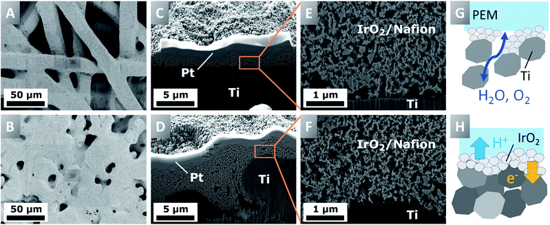
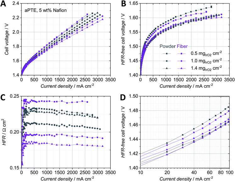
Porous titanium layers can be made of powder-sintered or fiber-sintered materials and are characterized via e.g. the size of the pristine powder particles or fibers as well as the final porosity, pore size and layer thickness. The structure of the PTLs has a crucial impact on the manufacturing of aPTEs and furthermore influences the performance of the MEA.10,21 In case the pores are much larger than the size of the catalyst particles, parts of the catalyst layer could be sprayed deep into the pores at great distances from the membrane and could be therefore inactive for the OER. The pore size and therefore the surface roughness were also expected to have a similar impact to that in CCM-configurations on the interfacial contact area between the PTL and catalyst layer as well as on the mass transport behavior.22,23Surprisingly, the aPTEs based on the denser powder-sintered PTLs did not outperform the fiber-sintered substrates, as was expected from the structural analysis. In contrast, the fiber PTE-configuration exhibited a better cell polarization behavior for loadings above 1.0 mgIrO2 cm−2 (Fig. 3A). The HFR-free cell voltage (Fig. 3B) showed no significant differences of mass transport losses between the different aPTEs. There were, however, differences in the HFR between the different loadings as well as the different titanium substrates (Fig. 3C). The HFRs of the aPTEs with loadings of 1.0 mgIrO2 cm−2 and 1.4 mgIrO2 cm−2 were lower when using a fiber PTL. This was not expected, since in theory the smoother surface of the powder-sintered substrates should have increased the electric contact area between the catalyst layer and PTL. The opposite effect was observed, with even a stronger difference in HFR between the fiber- and powder-sintered materials at higher noble metal loadings. The higher HFR for the powder-sintered aPTEs could be explained by an effect visible on the cross-sections of that layer (Fig. 2D). The smaller pores of the powder-sintered PTL were partly filled with catalyst material leading to a locally increased thickness of the catalyst layer and therefore longer pathways for electrons. However, for noble metal loadings as low as 0.5 mgIrO2 cm−2 the HFR was lower when using the smoother powder-sintered PTL. A smoother PTL could therefore be beneficial for the in-plane conductivity of low-loaded catalyst layers. The slight decrease in the HFR with increasing current density may be due to the increase in waste heat production and a deviation from thermal equilibrium (see e.g.ref. 22–24). In general, the higher the noble metal loading of the aPTEs, the lower the kinetic overpotential (Fig. 3D). Contrary to our expectations, the deposition of catalyst material into the bigger pores of the titanium fibers did not significantly affect the kinetic overpotential. The direct electronic interface between the catalyst layer and PTL, as is the case for both the fiber- and powder-sintered aPTEs, could therefore have had a greater influence on the kinetic overpotential than a changed protonic interface between the catalyst layer and membrane. The direct electronic interface between the catalyst layer and electrically conductive substrate was, at least according to Mo et al., essential for a sufficiently high catalyst utilization in CCM-configurations.25 Due to the better performance on average, as well as the superior materials characteristics such as a higher degree of interconnected pores,26 fiber-sintered PTLs were used as substrates for the aPTEs further investigated in this work.
Influence of the Nafion content in the catalyst layer
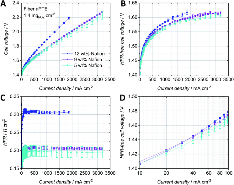
The Nafion content in the catalyst layer is a key parameter to reduce all three main contributions to the overpotential, i.e. ohmic, kinetic and mass transport. The amount of ionomer in the catalyst layer has an influence on its structure itself as well as on the electric interface with the PTL and on the protonic interface with the membrane.27,28 An optimized three-phase boundary between the catalyst particles, water supply and ionomer is essential to achieve the highest activity of the catalyst material possible. The ratio between ionomer and catalyst particles also influences the ohmic region, due to influences on the electric resistance within the catalyst layer as well as the electric resistance towards the PTL. A reduced porosity of the catalyst layer depending on the Nafion content as well as increased protonic resistances within the catalyst layer could furthermore increase mass transport losses. For anodes in the CCM-configuration, several optimum Nafion contents were found depending on the catalyst material and fabrication technique. For example, Xu et al. reported an optimum Nafion content of 25 wt% for a CCM with 1.5 mg cm−2 Ru0.7Ir0.3O2 spray coated on a PTFE sheet and hot-pressed onto a Nafion 117 membrane.27 A similar value of 30 wt% Nafion was found for a CCM with 1.5 mgIrblack cm−2 brushed onto a Nafion 1135 membrane.28 Bernt et al. reported a lower optimum Nafion content of 11.6 wt% when using 2 mgIr cm−2 of a supported IrO2/TiO2 catalyst.29 Since a porous titanium substrate was used for depositing the catalyst layer on top and not a flat membrane, we expected the optimum Nafion content of anodes in the PTE-configuration to vary from the values reported for the CCM-configurations.The lower the Nafion content, the better the overall performance of the aPTEs (Fig. 5A). The HFR-free cell voltage (Fig. 5B) increased with increasing Nafion content, most probably due to the filling of pores with Nafion and therefore increased mass transport losses. The significant increase of the HFR (Fig. 5C) at 12 wt% Nafion could be due to a worse electric interface between the catalyst layer and titanium PTL (compare to Fig. 4B). Since increasing the Nafion content also increased the thickness of the catalyst layer, pathways became longer which additionally could have led to a higher ohmic and also mass transport overpotential. The polarization data for the aPTEs were in good agreement with findings for anode catalyst layers in the CCM-configuration. Bernt et al. also observed a significant increase of the HFR when the Nafion loading was above a certain threshold, which was around 20 wt% for the supported IrO2 catalyst in the CCM-configuration.29 The reproducibility was the worst for the fiber aPTE with 5 wt% Nafion already in the kinetic region (Fig. 5D) and became more pronounced with increasing current density. A higher Nafion content did slightly increase the kinetic overpotential most likely caused by the occurrence of mass transport losses even at relatively small current densities. To further study the impact of different noble metal loadings on the polarization behavior, fiber aPTEs with a Nafion content of 9 wt% and varying IrO2 loadings were fabricated as a compromise between performance and reproducibility.
Influence of the IrOx loading
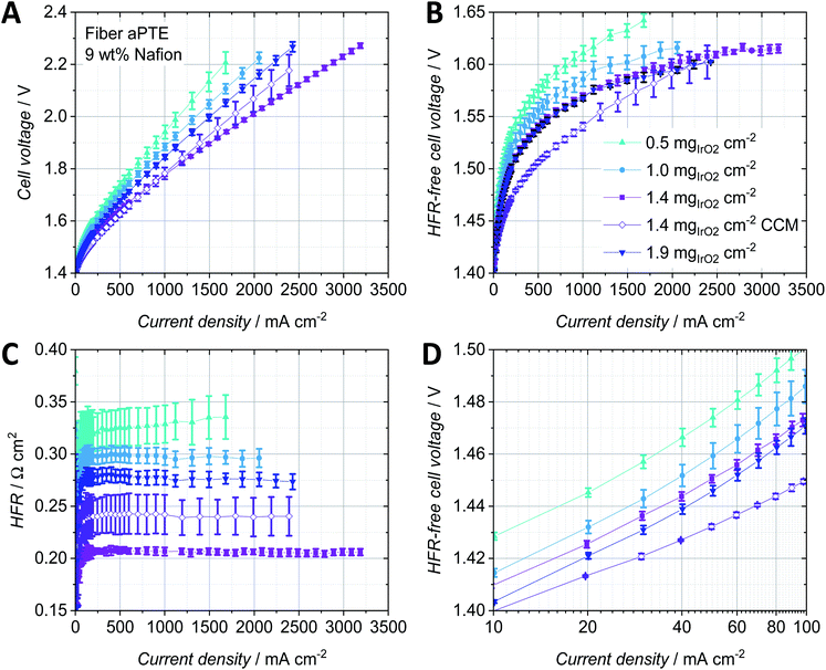
To increase the activity of the anodic catalyst layer, the catalyst loading and therefore the number of active sites need to be increased. But when increasing the noble metal loading, both the thickness of the catalyst layer and the amount of the material that is deposited into the pores of the PTL are also typically increased.18 Therefore, mass transport properties change as a function of catalyst layer thickness. For anodes in the CCM-configuration, several studies on the influence of the noble metal loading and ionomer content exist. For example, Rozain et al. found an optimal catalyst loading at the anode when using 0.5 mgIrO2 cm−2 with 10 wt% Nafion.30 For loadings below 0.5 mgIrO2 cm−2, the use of a conductive support was suggested, to establish electrical contact with and activate every catalyst particle due to the reduced in-plane conductivity, which was also identified by Bernt et al. as a structural challenge for low loaded electrodes.1 When using aPTEs, the electric contact area between catalyst particles and the PTL is good compared to that in CCM type configurations but still the in-plane conductivity of the catalyst layer is highly dependent on the roughness of the PTL as discussed when comparing the powder-sintered substrates with the fiber-sintered substrates. Su et al. studied low loading anodes with respect to the Nafion content and concluded that for loadings as low as 0.38 mgIrO2 cm−2 a Nafion content of 5 wt% is still sufficient.31 The influence of the iridium loading on the polarization behavior of aPTEs was investigated in the following and compared to studies on the anode catalyst layer in CCM-configurations.For the tested fiber aPTEs with 9 wt% Nafion, an optimum loading of 1.4 mgIrO2 cm−2 was found (Fig. 6A). The best aPTE showed a better average overall performance than the reference CCM with the same anode catalyst layer composition. The HFR-free cell voltage as a combination of kinetic and mass transport losses (Fig. 6B) interestingly showed no significant difference between aPTEs with 1.4 and 1.9 mgIrO2 cm−2 loading. The CCM-configuration performed the best in terms of HFR-free cell voltage. It should be noted, however, that the relatively better polarisation behavior of the CCM-configuration diminished with increasing current densities. The superior overall performance of the aPTE with 1.4 mgIrO2 cm−2 compared to the other MEA-configurations was most likely due to the lowest HFR (Fig. 6C), which also showed the best reproducibility. With reduced catalyst layer loadings, the reproducibility of the HFR of the aPTEs became worse. The CCMs showed, on average, a higher HFR than the PTE with the same catalyst loading. It has to be stated, however, that the anode catalyst layer deposited on the reference CCM was optimized for the PTEs in terms of Nafion content. Thus, an optimized CCM-configuration with the same noble metal loading but an optimized amount of Nafion could lead to an improved HFR and therefore better performance of the CCM-configuration. Nevertheless, in this work the same anode catalyst layer composition was chosen for the sake of comparability and simplicity. The kinetic region of the HFR-free cell voltage (Fig. 6D) showed that the CCM has the best performance, most probably due to the largest direct protonic contact area of the catalyst layer with the PEM. The higher the noble metal loading of the aPTEs, the smaller the kinetic overpotential. The kinetic region was however already affected at about 20 mA cm−2 by mass transport losses. Since at such low current densities, bubble and diffusion overpotentials should not dominate,32 a changed proton conductivity within the catalyst layer could have been the reason for this behavior. As already described by Babic et al. for CCMs,33 the thickness of the catalyst layers increased with increasing noble metal loadings and therefore protonic pathways increased. This then most probably led to increased protonic resistances within the catalyst layer.
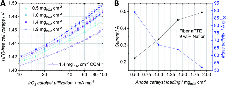
A comparison between the HFR-free cell voltage at low current densities (Fig. 6D) and the HFR-free cell voltage at low current densities per milligram IrO2 (Fig. 7A) helped us to further study the impact of the noble metal loading on the cell performance. At an HFR-free cell voltage of 1.47 V all PTE-configurations were compared with each other in terms of current density and mass specific activity dependent on the noble metal loading (Fig. 7B). The reference CCMs showed both the best catalyst utilization due to the lowest HFR-free cell voltage per noble metal loading (Fig. 7A) and the lowest overpotential in the kinetic region (Fig. 6D). Increasing the noble metal loading of the aPTEs reduced the kinetic overpotential (Fig. 6D), but at the same time the effective catalyst utilization was reduced (Fig. 7A). This opposing trend of kinetic losses vs. mass activity is shown in a combined graph (Fig. 7B). The cell current and mass activity at a set HFR-free cell voltage of 1.47 V were plotted against IrO2 loading. Increasing the noble metal loading increased the specific current density, but at the same time reduced the mass specific activity. Babic et al. reported a similar opposing trend of activation losses vs. effective catalyst utilization for anode catalyst layers with different loadings for the CCM-configuration.33
Stability test
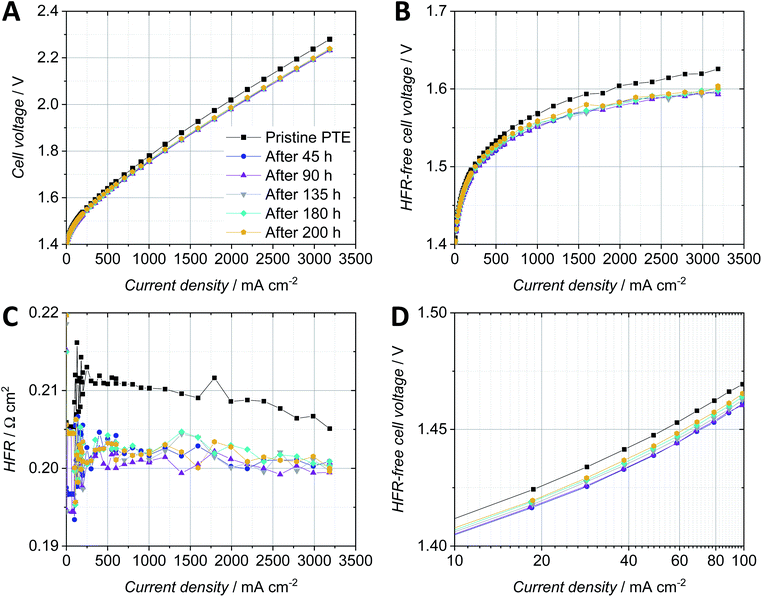
The fiber-sintered PTE with a loading of 1.4 mg cm−2 and 9 wt% Nafion showed the highest reproducibility and reasonable performance in comparison with the CCM-configuration with the same anodic catalyst layer sprayed on the membrane, and was therefore chosen for the durability test. Fig. 8 shows the cell voltage over time while applying a constant current of 2 A cm−2. Polarization curves were recorded for the pristine PTE and after every segment (Fig. 9).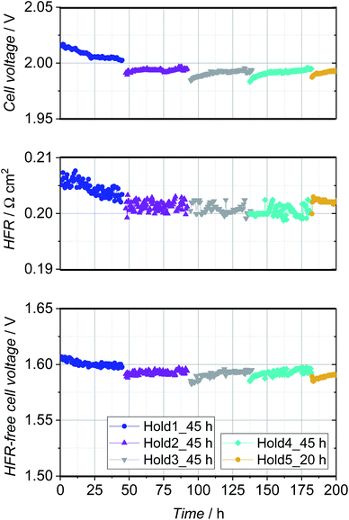 | ||
| Fig. 8 Cell voltage, HFR and HFR-free cell voltage during the 200 h stability test. A constant current of 2 A cm−2 was set and polarization curves were recorded after every segment. | ||
The cell voltage improved significantly during the first hold of 45 h, and so did the HFR-free cell voltage and the HFR of the PTE-configuration (Fig. 8). This behavior can be related to the break-in of the cell due to the activation of the catalyst or impurities washed out of the Nafion membrane. In the second constant current hold of 45 h, the overall cell voltage and HFR stabilized and so did the HFR-free cell voltage. Subsequently, an increased degradation of approx. 200 μV h−1 was observed in segment 3 and 260 μV h−1 in segment 4, which can be assigned almost exclusively to the HFR-free cell voltage and in particular to the anodic catalyst. However, this is of apparent nature and is reversed as soon as lower potentials are present and the metal oxide catalyst is reduced with permeated hydrogen.17,34
The polarization curves recorded for the pristine PTE-configuration as well as after every segment of the constant current hold showed a significant improvement of cell performance after the first constant current hold of 45 h (Fig. 9A). The cell voltage was then stable for the subsequent 155 h of the durability test. The HFR-free cell voltage (Fig. 9B) as a combination of the kinetic and mass transport overpotentials also significantly improved by 20 mV at 2 A cm−2 after the first 45 h constant current hold and did not show remarkable changes during the remaining time of the test. The HFR (Fig. 9C) improved by ca. 8 mΩ cm2 at 2 A cm−2 after the first constant current hold and stabilized around a value of 200 mΩ cm2. The reduction of the kinetic overpotential by ca. 10 mV at low current densities was probably due to the activation of the catalyst during the first constant current hold (Fig. 9D). The kinetic overpotential slightly increased for the polarization curves recorded in the subsequent hours.
The PTE-configuration tested in this work showed a similar stability compared to the literature regarding the characterization of commercial CCM-configurations.14,17
Conclusions
In this work, anodic porous transport electrodes (aPTEs) were fabricated via spray coating of IrO2 and Nafion-based catalyst layers on top of two different titanium porous transport layers (PTLs). The aPTEs were then pressed against a Nafion 117 membrane and a cathodic porous transport electrode (cPTE) made of a carbon cloth material coated with 0.5 mgPt/C cm−2 (60% platinum on Vulcan). The fiber-sintered PTL outperformed the powder-sintered aPTE for loadings above 1.0 mgIrO2 cm−2 despite a coarser surface. Reducing the amount of ionomer in the catalyst layers with a loading of 1.4 mgIrO2 cm−2 to only 5 wt% showed reduced ohmic and mass transport overpotentials. Reducing the Nafion content in the catalyst ink however led to inhomogeneous spray patterns and therefore a worse reproducibility. Optimizing the deposition technique is therefore suggested to further reduce the Nafion content for the development of high performance fiber-sintered aPTEs. When the Nafion content was kept at 9 wt% in the catalyst layer, the optimum noble metal loading was 1.4 mgIrO2 cm−2. With this amount of Nafion in the catalyst layer, a very good reproducibility was reached, especially when compared to CCMs with the same anode catalyst layer composition. The optimum Nafion content and noble metal loading for aPTEs are most likely different for every new material combination, due to the complex interplay between the porous substrate, catalyst loading, and Nafion content, as well as operating conditions. Optimizing every aPTE step by step as shown in this work is therefore too time consuming and advanced structural models are more than needed to help to reduce and define the wide range of fabrication parameters.In the applied test cell setup, the aPTEs fabricated in this work outperformed a reference CCM with equivalent catalyst loading in terms of HFR, reproducibility and the tendency towards improved mass transport at high current densities. The development and further optimization of aPTEs for PEMWEs is therefore highly interesting and promising since not only could the performance be further improved but also the fabrication efforts could be reduced. Due to the simplified direct spraying of the anode catalyst layer on top of the titanium substrates, no hot pressing or transfer substrates are needed to manufacture a PTE-type MEA.
The stable operation of the most reproducible fiber-sintered aPTE was shown in a 200 h durability test when applying 2 A cm−2 constant current. The overall cell voltage improved significantly after the first 45 h mainly due to improved kinetic and ohmic regions. Then, the cell performance stabilized for the remaining time of the durability test. The directly spray-deposited anodic catalyst layer therefore showed a mechanically stable interface between the catalyst layer and anodic PTL, ensuring a high catalyst utilization and electrical connectivity as well as sufficient mass transport.
Conflicts of interest
There are no conflicts of interest to declare.Acknowledgements
The authors gratefully acknowledge the financial support by the Federal Ministry of Education and Research of Germany in the framework of Power-MEE (03SF0536E).References
- M. Bernt, A. Siebel and H. A. Gasteiger, J. Electrochem. Soc., 2018, 165, F305–F314 CrossRef CAS.
- H. Yu, N. Danilovic, Y. Wang, W. Willis, A. Poozhikunnath, L. Bonville, C. Capuano, K. Ayers and R. Maric, Appl. Catal., B, 2018, 239, 133–146 CrossRef CAS.
- S. M. Alia, S. Shulda, C. Ngo, S. Pylypenko and B. S. Pivovar, ACS Catal., 2018, 8, 2111–2120 CrossRef CAS.
- U. Babic, M. Suermann, F. N. Büchi, L. Gubler and T. J. Schmidt, J. Electrochem. Soc., 2017, 164, F387–F399 CrossRef CAS.
- M. Breitwieser, M. Klingele, S. Vierrath, R. Zengerle and S. Thiele, Adv. Energy Mater., 2017, 38, 1701257 Search PubMed.
- M. Carmo, D. L. Fritz, J. Mergel and D. Stolten, Int. J. Hydrogen Energy, 2013, 38, 4901–4934 CrossRef CAS.
- L. Cindrella, A. M. Kannan, J. F. Lin, K. Saminathan, Y. Ho, C. W. Lin and J. Wertz, J. Power Sources, 2009, 194, 146–160 CrossRef CAS.
- M. Qian and F. H. Froes, Titanium Powder Metallurgy, Elsevier, Butterworth-Heinemann, Waltham, MA, 2015, ISBN: 9780128000540 Search PubMed.
- P. Lettenmeier, S. Kolb, F. Burggraf, A. S. Gago and K. A. Friedrich, J. Power Sources, 2016, 311, 153–158 CrossRef CAS.
- S. A. Grigoriev, P. Millet, S. A. Volobuev and V. N. Fateev, Int. J. Hydrogen Energy, 2009, 34, 4968–4973 CrossRef CAS.
- F. M. Sapountzi, S. C. Divane, E. I. Papaioannou, S. Souentie and C. G. Vayenas, J. Electroanal. Chem., 2011, 662, 116–122 CrossRef CAS.
- B.-S. Lee, S. H. Ahn, H.-Y. Park, I. Choi, S. J. Yoo, H.-J. Kim, D. Henkensmeier, J. Y. Kim, S. Park, S. W. Nam, K.-Y. Lee and J. H. Jang, Appl. Catal., B, 2015, 179, 285–291 CrossRef CAS.
- S. Choe, B.-S. Lee, M. K. Cho, H.-J. Kim, D. Henkensmeier, S. J. Yoo, J. Y. Kim, S. Y. Lee, H. S. Park and J. H. Jang, Appl. Catal., B, 2018, 226, 289–294 CrossRef CAS.
- C. Rakousky, U. Reimer, K. Wippermann, M. Carmo, W. Lueke and D. Stolten, J. Power Sources, 2016, 326, 120–128 CrossRef CAS.
- C. Liu, M. Carmo, G. Bender, A. Everwand, T. Lickert, J. L. Young, T. Smolinka, D. Stolten and W. Lehnert, Electrochem. Commun., 2018, 97, 96–99 CrossRef CAS.
- T. Bystron, M. Vesely, M. Paidar, G. Papakonstantinou, K. Sundmacher, B. Bensmann, R. Hanke-Rauschenbach and K. Bouzek, J. Appl. Electrochem., 2018, 48, 713–723 CrossRef CAS.
- M. Suermann, B. Bensmann and R. Hanke-Rauschenbach, J. Electrochem. Soc., 2019, 166, F645–F652 CrossRef.
- M. Bühler, P. Holzapfel, D. McLaughlin and S. Thiele, J. Electrochem. Soc., 2019, 166, F1070–F1078 CrossRef.
- M. Feng, R. Qu, Z. Wei, L. Wang, P. Sun and Z. Wang, Sci. Rep., 2015, 5, 9859 CrossRef CAS PubMed.
- F. Hegge, R. Moroni, P. Trinke, B. Bensmann, R. Hanke-Rauschenbach, S. Thiele and S. Vierrath, J. Power Sources, 2018, 393, 62–66 CrossRef CAS.
- M. Bühler, C. Klose, F. Hegge, T. Lickert and S. Thiele, ECS Trans., 2017, 80, 1069–1075 CrossRef.
- M. Suermann, K. Takanohashi, A. Lamibrac, T. J. Schmidt and F. N. Büchi, J. Electrochem. Soc., 2017, 164, F973–F980 CrossRef CAS.
- T. Schuler, T. J. Schmidt and F. N. Büchi, J. Electrochem. Soc., 2019, 166, F555–F565 CrossRef CAS.
- M. Suermann, T. J. Schmidt and F. N. Büchi, Electrochim. Acta, 2016, 211, 989–997 CrossRef CAS.
- J. Mo, Z. Kang, S. T. Retterer, D. A. Cullen, T. J. Toops, J. B. Green Jr, M. M. Mench and F.-Y. Zhang, Sci. Adv., 2016, 2, e1600690 CrossRef PubMed.
- P. Liu and G.-F. Chen, Porous Materials: Processing and Applications, Elsevier, Butterworth-Heinemann, Amsterdam, Boston, Paris, 2014, ISBN: 0124078370 Search PubMed.
- W. Xu and K. Scott, Int. J. Hydrogen Energy, 2010, 35, 12029–12037 CrossRef CAS.
- L. Ma, S. Sui and Y. Zhai, Int. J. Hydrogen Energy, 2009, 34, 678–684 CrossRef CAS.
- M. Bernt and H. A. Gasteiger, J. Electrochem. Soc., 2016, 163, F3179–F3189 CrossRef CAS.
- C. Rozain, E. Mayousse, N. Guillet and P. Millet, Appl. Catal., B, 2016, 182, 153–160 CrossRef CAS.
- H. Su, V. Linkov and B. J. Bladergroen, Int. J. Hydrogen Energy, 2013, 38, 9601–9608 CrossRef CAS.
- D. G. Bessarabov, H. Wang, H. Li and N. Zhao, PEM Electrolysis for Hydrogen Production: Principles and Applications, CRC Press, Boca Raton, Florida, 2016, ISBN: 9781138775497 Search PubMed.
- U. Babic, E. Nilsson, A. Pătru, T. J. Schmidt and L. Gubler, J. Electrochem. Soc., 2019, 166, F214–F220 CrossRef CAS.
- A. Weiß, A. Siebel, M. Bernt, T.-H. Shen, V. Tileli and H. A. Gasteiger, J. Electrochem. Soc., 2019, 166, F487–F497 CrossRef.
| This journal is © The Royal Society of Chemistry 2019 |

