 Open Access Article
A highly stretchable strain-insensitive temperature sensor exploits the Seebeck effect in nanoparticle-based printed circuits†
Yangyang
Xin
a,
Jian
Zhou
ab and
Gilles
Lubineau
 *a
*a
aKing Abdullah University of Science and Technology (KAUST), Physical Sciences and Engineering Division (PSE), COHMAS Laboratory, Thuwal 23955-6900, Saudi Arabia. E-mail: gilles.lubineau@kaust.edu.sa; Tel: +966 (12) 808 2983
bSchool of Materials Science and Engineering, Sun Yat-sen University, Guangzhou 510275, Guangdong, P. R. China
First published on 3rd October 2019
Abstract
Stretchable temperature sensors are critical components in soft robotics. Most existing temperature-sensing technologies feature a strong coupling between the response to temperature and response to deformation of the measured object, resulting in strain-polluted temperature measurements. Here we leverage the Seebeck effect in nanoparticle-based printed circuits. Using nanoparticle-based circuits as conductive wires provides stretchability. While a resistive measurement is highly perturbed by strain variations, using a Seebeck-induced change in the voltage ensures that the measured signal is insensitive to strain. Two nano-structured wires made of different materials are printed and embedded in a soft polymeric film to form a micro-thermocouple. This temperature sensor shows good stretchability up to 40% strain, high linearity of response, and excellent repeatability between different samples.
1. Introduction
With the increasing demand for stretchable sensors in applications such as soft robotics,1–3 prostheses,4,5 and human/machine interfaces,6,7 significant developments are needed. Many new sensors based on nanomaterials have been reported, e.g., wearable humidity sensors,8–10 stretchable strain sensors,11–13 soft or flexible pressure sensors,14–16 and soft temperature sensors.17–19However, most of these new sensors are not only sensitive to what they are intended to measure, but also to other factors, among which the most common and influencing one is the deformation of the structure (strain) they are attached to. Temperature sensors are also susceptible to the influence of deformation.20–24 Temperature sensors can be sorted into three categories, pyroelectric temperature detectors, resistive temperature detectors, and thermistors, all of which suffer from strain-polluted temperature measurements.25 Strain may influence the signal just as significantly as changes in temperature, making such sensors inoperative.
The stretchability of existing temperature sensors is also quite limited. Some studies improved the stretchability of flexible temperature sensors by redesigning their geometry into a stretchable “S” shape or a microstructure created by buckling.26–29 The idea here is always the same: create a structure that can sustain large transformations without experiencing large strain, thus avoiding local failure. Printing conductive ink into an “S” shape on a soft substrate is an efficient way to increase the stretchability by reducing the axial strain on the conductive pathway.29 Recently, an “S”-shaped graphene thermistor printed on a flexible polydimethylsiloxane (PDMS) substrate was reported.29 This temperature sensor was stretched up to 50% while maintaining its temperature-sensing properties. However, this sensor still showed a large coupling effect with the strain, which increased the complexity of calibration. A skin-inspired, highly stretchable, and conformable matrix network for multifunctional sensing was also reported.26 In this research, sensors with different functionalities were interconnected with specifically structured stretchable wires. However, these sensors were not protected and fragile. In another study, a stretchable silicon-nanoribbon electronic device for skin prostheses was fabricated in which structured cables with an “S”-like shape were used to achieve high stretchability. In this case, however, the functional layer was covered with polyimide (PI), which induced some detrimental high stresses into the stiff silicon-based functional layer.5 As mentioned above, another method of introducing stretchability is to design a pre-strain triggered buckled structure.28 In this research, the temperature sensor was stretched to 30% without a visible coupling effect from strain. The buckled microstructure was formed by transferring a thin Cr/Au film to a stretched PDMS substrate and then releasing the substrate.28 The drawbacks of this pre-straining method are evident. First, it is difficult to use a pattern integrating a lot of sensors. Second, the buckling allows stretchability along its preferential direction only, so obtaining isotropic stretchability through this method is very challenging. Finally, the temperature measurement is still polluted by strains when a complex multi-axial strain state develops.
An alternative approach is to move away from thermistors and use the Seebeck effect instead.20,30,31 Good stretchability and temperature sensing were already demonstrated in a temperature sensor made from microstructure-frame-supported organic thermoelectric materials.30 However, this temperature sensor only operated along the thickness direction, while monitoring the temperature gradient across the surface is needed. One solution is to print a conductive polymer and nanomaterials onto a flexible surface as a microthermocouple.20,31 However, due to the poor stretchability of the conductive materials used in these first demonstrations, the sensors developed so far have not been stretchable.
To obtain temperature sensors that are both strain-independent and stretchable, we create thermocouples with nanoparticle-based printed circuits on an elastic PDMS substrate. Our examples are based on a combination of the two of the three following materials: single-wall carbon nanotubes (SWCNTs), multi-wall carbon nanotubes (MWCNTs), and silver nanowires (AgNWs). The AgNW conductive networks can sustain the conductivity and keep the Seebeck coefficient unchanged when the sensor is subjected to high strains, thus giving the sensor high stretchability and strain-independent characteristics. Our best sensor shows good stretchability (up to 40%) with a non-strain-polluted temperature measurement, making it attractive for applications in stretchable electronics.
2. Experimental section
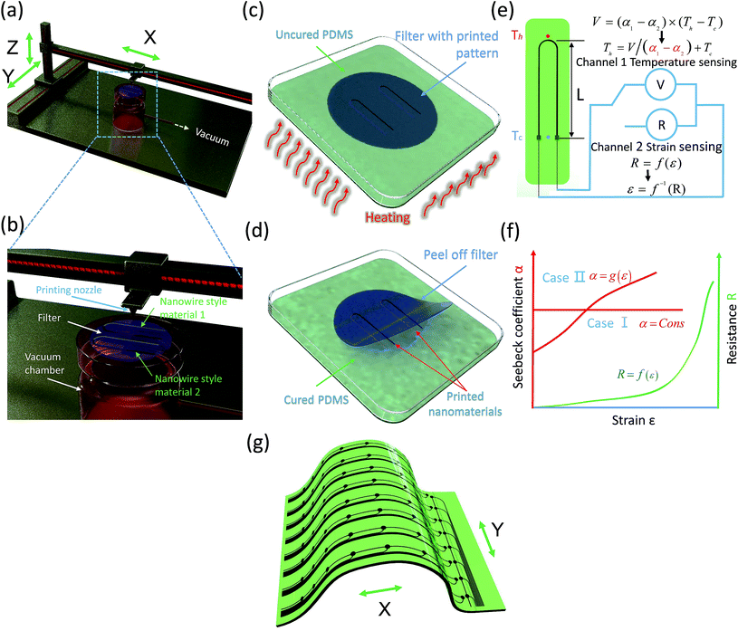
The design strategy is illustrated in Fig. 1. Two different nanoparticle-based circuits were printed in a “U” shape onto a soft substrate. The difference between the Seebeck coefficients of the two circuit materials generated a voltage proportional to the temperature difference between the cold (Tc) and hot (Th) points. Thus, this sensor used the Seebeck voltage (V) generated by the temperature difference (ΔT = Th − Tc) between the two ends of the sensor to monitor the temperature. In addition, nanoparticle-based printed circuits are highly stretchable conductors. These can sustain large deformations while preserving the needed conductivity, and their changes in resistance can be eventually used to monitor the strain as in any nanoparticle-based resistor. This strain measurement is classical as the resistance of nanoparticle networks is well known to increase during mechanical stretching. This results in the classical change in resistance with strain, as illustrated in Fig. 1(f). How much the measured temperature would be dependent on the stretching level is directly related to how the Seebeck coefficient (α) of these materials evolves with stretching. Two configurations are possible. In case I, the strain does not influence the Seebeck effect; in another words, the temperature sensor is strain-independent. In case II, the strain does influence the Seebeck effect. Therefore, we would need to obtain the strain measurement first from the strain-sensing function of the sensor in order to calibrate the Seebeck coefficient. Our main observation in this paper is that the Seebeck coefficient of the as-fabricated nanoparticle-based circuits is not dependent on strain, as we will demonstrate.Materials
We used three types of nanomaterials: SWCNTs, MWCNTs, and AgNWs. The SWCNTs were provided by CheapTubes with lengths of 5 to 30 μm and diameters of 1 to 2 nm. The MWCNTs were also provided by CheapTubes with lengths ranging from 3 to 30 μm and outer diameters from 13 to 18 nm. The AgNWs were purchased from Sigma-Aldrich, with a length of 10 μm and a diameter of 60 nm, already dissolved in isopropyl alcohol with 0.5 wt%. Methanesulfonic acid (CH3SO3H) with over 99.0 wt% purity was also purchased from Sigma-Aldrich.Preparation of the printing ink
We dissolved 2 wt% of either SWCNTs or MWCNTs in methanesulfonic acid. The detailed process can be found in our previous studies.2,32 The as-received AgNWs were already dissolved in isopropyl alcohol. We used this suspension directly without any change in concentration.Ink printing on the nano-filter
We used a Microplotter II ink printer system (SonoPlot company) to print two different inks in a “U” shape, onto a nanofilter (Nuclepore polyester), as shown in Fig. 1, S1, and S2.† The two materials (SWCNTs/MWCNTs and either SWCNTs/AgNWs or MWCNTs/AgNWs depending on the ink) have a junction at the top of the “U” shape. Due to the high viscosity of our inks, we used a syringe pump (8 μl min−1, 250 μm inner-diameter printing nozzle) to supply the inks instead of an ultrasonic ink supply system (Fig. S1(d) and (e)†). The solvents were removed using a vacuum-assisted deposition process, as shown in Fig. 1(b) and S1(c),† where a glass support combined with the nanofilter formed a vacuum chamber to absorb the solvent. Using vacuum-assisted deposition, the solvent was removed as soon as the ink was deposited, which increased the printing quality by preventing the ink from flushing everywhere. After the vacuum-assisted deposition, the small quantity of the remaining solvent either evaporated spontaneously into the air (case of isopropyl alcohol) or was washed away using distilled water (case of methanesulfonic acid). We printed three types of samples: SWCNTs/AgNW, MWCNTs/AgNWs, and SWCNTs/MWCNTs. When printing the SWCNTs/AgNW and MWCNTs/AgNW samples, we printed the CNTs first to avoid flushing AgNWs during the washing process.Preparation of nano-material based stretchable sensors
The first step consisted of pouring 5.3 g of PDMS with a curing agent into a Petri dish. After one hour, PDMS was partially cured. Then, the “U”-shape was transferred by bringing the printed face of the nanofilter into contact with the sticky, partially cured PDMS substrate, as shown in Fig. S2(b).† Next, the Petri dish was heated in an oven at 80 °C for 10 minutes to complete the curing of PDMS and to encapsulate the nanoparticles on the surface of PDMS.32,33 Then, the nanofilter was removed either by carefully peeling off the filter from one side to the other (Fig. S2(c)†) or by using dichloromethane (DCM) to dissolve the PET filter (Fig. S2(d)†). The SEM images of the nano materials before and after the transfer to the PDMS substrate are shown in Fig. S3.† We describe the drawbacks of both methods in the ESI.† After removing the filter, the sample was connected to copper-wire electrodes. To embed the functional “U” shape, another 5.3 g of PDMS was poured over the top of the sample, followed by one hour of heat treatment at 80 °C. We tested the response of samples with different thicknesses. Due to the high viscosity of PDMS, it was difficult to fabricate thin samples with a uniform thickness based on gravity alone. Therefore, we used hexane to dilute PDMS to a ratio of 1![[thin space (1/6-em)]](https://www.rsc.org/images/entities/char_2009.gif) :
:![[thin space (1/6-em)]](https://www.rsc.org/images/entities/char_2009.gif) 2 (PDMS
2 (PDMS![[thin space (1/6-em)]](https://www.rsc.org/images/entities/char_2009.gif) :
:![[thin space (1/6-em)]](https://www.rsc.org/images/entities/char_2009.gif) hexane). To prepare samples with different thicknesses, 2 g, 4 g, 6 g, and 8 g of the mixed solution were put into Petri dishes. Then, the four Petri dishes were put in a fume hood for two hours to completely evaporate the hexane. After connecting cables and embedding the “U”-shape ink under another PDMS substrate of identical thickness, we obtained four samples with thicknesses of 0.47 mm, 0.82 mm, 1.02 mm, and 1.47 mm.
hexane). To prepare samples with different thicknesses, 2 g, 4 g, 6 g, and 8 g of the mixed solution were put into Petri dishes. Then, the four Petri dishes were put in a fume hood for two hours to completely evaporate the hexane. After connecting cables and embedding the “U”-shape ink under another PDMS substrate of identical thickness, we obtained four samples with thicknesses of 0.47 mm, 0.82 mm, 1.02 mm, and 1.47 mm.
Characterization
A 5944 Instron machine was used for mechanical extension tests. The Seebeck voltage and electrical resistance of the specimen were measured with a KEYSIGHT 34461A digital multimeter. To test the temperature difference between the hot point and the cold point, we used a picometer combined with two K-type thermocouples (Fig. S4(a) and (d)†). To ensure a homogenous temperature field through the thickness, the sample was clamped between two identical electrical heaters, as shown in Fig. S4(b).† The heaters were powered by a direct-current power source (Fig. S4(c)†).3. Results and discussion
Temperature sensing
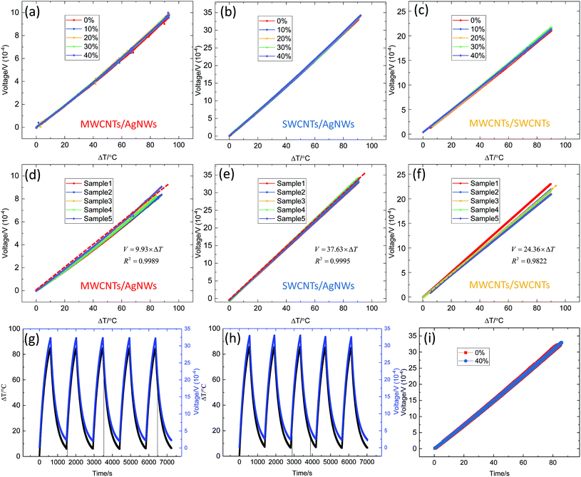
The changes in the Seebeck voltage corresponding to the temperature difference for the three types of investigated material associations are shown in Fig. 2(a)–(c). The voltage–ΔT curves almost overlap under 0%, 10%, 20%, 30%, and 40% strains for all three types of samples. Therefore, we conclude that the strain has a negligible effect on the temperature/voltage relationship. This validates our strategy of using the Seebeck effect to obtain a strain-independent temperature measurement. All of the three types of sensors showed good linearity during temperature sensing, but with different slopes, which means different Seebeck coefficients between different types of sensors. The slope is ascribed to the Seebeck effect formula V = αΔT, in which V is the Seebeck voltage, α represents the contrast in Seebeck coefficients determined by the material type, and ΔT is the temperature difference. The Seebeck coefficient of the SWCNTs/AgNW sensor can reach up to 37 μV °C−1 (Fig. 2(b)), higher than both 23 μV °C−1 for the MWCNTs/SWCNT sensor (Fig. 2(c)) and 11 μV °C−1 for the MWCNTs/AgNW sensor (Fig. 2(a)). Good linearity is a critical factor in engineering as it avoids complex calibration procedures.We investigated the repeatability of temperature sensing between different samples. Fig. 2(d) shows the Seebeck voltage change with temperature difference for five different MWCNTs/AgNW sensors. These five sensors show excellent consistency in temperature sensing which means high repeatability between different samples. Similar results are shown in Fig. 2(e) for SWCNTs/AgNW sensors and in Fig. 2(f) for MWCNTs/SWCNT sensors, both of which also feature good repeatability.
To test the repeatability of the sensors between the heating and cooling processes, we repeated a heating–cooling cycle test five times on one MWCNTs/SWCNT sensor under 0% (Fig. 2(g)) and 40% (Fig. 2(h)) strains. As shown in Fig. 2(g) and (h), the output voltage closely followed the change in temperature difference which means high repeatability between the heating and cooling processes. To further study the repeatability, we plotted the results shown in Fig. 2(g) and (h) together in Fig. 2(i). The overlapping response curves clearly show the repeatability of the sensor. No noticeable difference was observed between the results obtained under 0% and 40% strains, confirming that strain does not influence the repeatability of the sensor during the heating and cooling processes. Then, we investigated the performance of the sensor when it was subjected simultaneously to strain and temperature. The results are shown in Fig. S5† and prove again that this temperature sensor is insensitive to strain.
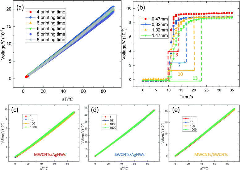
Now, we investigate how the sensing properties change with the density of the nanoparticle network. Fig. 3(a) shows the voltage/temperature response for the MWCNTs/SWCNT samples, where the density of the nanoparticle network was modified by changing the number of overlapping printed layers. We fabricated six samples, two with 4 layers, two with 6 layers, and two with 8 layers, as shown in Fig. 3(a). The results show that the density of the conductive networks almost does not influence the temperature sensing. This insensitivity of temperature sensing to the conductive-network density is advantageous for large-scale commercial production, where the printing quality and other printing parameters may vary around some nominal values. The insensitivity of the sensors to the density of the network also reflects insensitivity to stretching which results intrinsically from changes in the network density.
To investigate the influence of the substrate thickness on response time, we fabricated four different substrate thicknesses (0.47 mm, 0.82 mm, 1.02 mm, and 1.47 mm). We stimulated the sensors with a temperature difference of 40 °C. From Fig. 3(b), we see that the response times were 3 s, 7 s, 10 s, and 13 s for the samples with 0.47 mm, 0.82 mm, 1.02 mm, and 1.47 mm substrate thicknesses, respectively. The response time increased with increasing substrate thickness; thus, we can modify the response time for engineering applications.
Finally, we studied the stability of the voltage/temperature response after performing a large number of stretching/relaxing cycles. We performed 1000 cycles during which the peak strain was 40% for all three types of sensors, and we stopped at 1, 10, 100, and 1000 cycles to perform the temperature-sensing test. Fig. 3(c) shows the results of the MWCNTs/AgNW type of sensor, while the results of SWCNTs/AgNW and MWCNTs/SWCNT types of sensors are shown in Fig. 3(d) and (e), respectively (see more details about this test in Fig. S6–S8†). All three types of sensors showed good stability after long-term cyclic stretching/relaxing loading. We also tested the high-temperature stability and water durability34 of the as-fabricated temperature sensor, and the details are shown in the ESI.†
Strain sensing
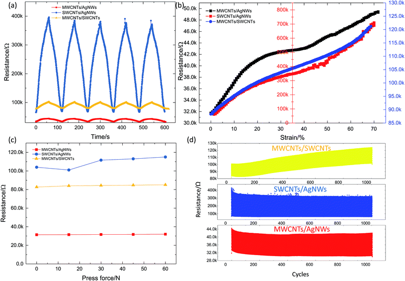
Our sensor design measures the change in the Seebeck-effect-induced voltage, resulting in strain-insensitive temperature sensing. However, we might still be interested in using this sensor as a classical strain sensor by monitoring its change in resistance during stretching.We tested the repeatability of the strain-sensing performance of all three sensor types during five stretching/releasing cycles (Fig. 4(a)). While the change in resistance with strain was very different for each sensor, the repeatability between the loading and unloading processes was good for all three. Next, we investigated the strain-sensing ranges of the sensors; the results are shown in Fig. 4(b). All the sensors were capable of monitoring a strain up to at least 70%. Then, we studied the sensitivity of each sensor to the surface pressure, using a cylindrical iron rod with a 10 mm diameter. As shown in Fig. 4(c), the resistance of the samples increased only slightly with increasing pressure; this increase was caused by a strain change perpendicular to the pressure, which was stimulated using the Poisson effect. To investigate the stability of the temperature sensors when being used as strain sensors, we performed a long-term cycling test with 1000 stretching/releasing cycles (Fig. 4(d)). The maximum strain was 40%. The MWCNTs/AgNW and SWCNTs/AgNW samples showed a stable response after the initial relaxation period. The MWCNTs/SWCNT sample shows an upward shift in its response as the number of loading cycles increased. The reason for this shift has not yet been investigated.
The observed strain-sensing features were similar to what has been classically observed in all strain sensors based on percolated systems of nanoparticles. We note that the as-fabricated sensors performed much better as temperature sensors via the Seebeck effect; their precision was not very high when used as resistance-based strain sensors.
Temperature-sensing application
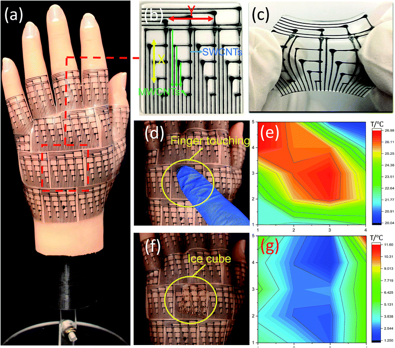
We made an array of seventeen 20-pixel temperature sensors by bonding them to the surface of a soft robotic hand as an artificial skin to monitor the temperature distribution across its surface (Fig. 5(a)). Fig. 5(b) shows the microstructure of the temperature-sensor array, which contained 20 pixels. We used four strips to measure the temperature gradient in the X direction and one strip to measure the temperature gradient in the Y direction. Each strip had five MWCNT lines and one SWCNT line to generate five temperature sensors at the intersecting points, as shown in Fig. 5(b). By obtaining the temperature gradient in both the X and Y directions and the temperature of the reference point, we could calculate the temperature of each pixel. The array was cured on a PDMS substrate to achieve good stretchability, as shown in Fig. 5(c). Because the voltage meter's needles must contact the printed line directly to obtain signals, we did not embed the array under another layer of PDMS. To test the feasibility of the array, we performed a pre-test (shown in Fig. S10†). In Fig. 5(d), we selected one array and touched it with a gloved finger to observe its response. Then we chose the lower left corner as the reference point and obtained the Seebeck voltage based on this reference point. We calculated the pixels' temperature using T = T1 + V/α, in which T1 is the temperature of the reference point and α is the Seebeck coefficient of the MWCNTs/SWCNT sensor. In this paper, we chose 24.36 μV °C−1 as the Seebeck coefficient of MWCNTs/SWCNTs and 21 °C as the temperature of the reference point measured with a thermocouple. We plotted the results from the finger touching test on a temperature map, as shown in Fig. 5(e). The temperature distribution shown in Fig. 5(e) matches the direction of the finger touching the temperature-sensor array as shown in Fig. 5(d). From Fig. 5(e), we see that the maximum measured temperature of the finger surface was 26.98 °C, which is lower than human body temperature. Next, we put an ice cube on the surface of the same array (Fig. 5(f)). The results are shown in the temperature map in Fig. 5(g). The minimum temperature of the ice was 1.25 °C, which is comparable to the temperature of an ice–water mixture. Based on this demonstration, we assert that this stretchable temperature sensor is a viable option for artificial skins used in soft robotics and other applications.4. Conclusion
In summary, this temperature sensor, which uses nanoparticle-based printed circuits and voltage induced by the Seebeck effect, can measure temperature precisely over a wide strain range with good strain insensitivity. It features good repeatability between different samples, a linear and stable response, and tolerance to manufacturing defects such as varying thicknesses of the functional layer of nanoparticles. The sensor is also capable of strain sensing when using resistance as the signal, but with less accuracy compared to temperature sensing. The proposed technology is fully scalable and can be readily implemented in the large-scale production of electronic skins.Author contribution statement
Y. X., G. L. and J. Z. conceptualized and supervised the study. Y. X. performed the experiments. Y. X., J. Z. and G. L. worked on the data analysis. G. L., Y. X. and J. Z wrote the manuscript.Data availability
The datasets generated during and/or analyzed during the current study are available from the corresponding author upon reasonable request.Conflicts of interest
The authors declare no financial and non-financial competing interest.Acknowledgements
The research reported in this publication was supported by the King Abdullah University of Science and Technology (KAUST), under award number BAS/1/1315-01-01.References
- Y. Cheng, R. Wang, J. Sun and L. Gao, A Stretchable and Highly Sensitive Graphene-Based Fiber for Sensing Tensile Strain, Bending, and Torsion, Adv. Mater., 2015, 27, 7365–7371 CrossRef CAS PubMed.
- J. Zhou, Y. Hu, X. Xu, F. Han and G. Lubineau, Fragmented Carbon Nanotube Papers for Ultrasensitive, Stretchable Strain Sensors, ACS Appl. Mater. Interfaces, 2017, 9, 4835–4842 CrossRef CAS PubMed.
- J. Zhou, X. Xu, Y. Xin and G. Lubineau, Coaxial Thermoplastic Elastomer-Wrapped Carbon Nanotube Fibers for Deformable and Wearable Strain Sensors, Adv. Funct. Mater., 2018, 28, 1705591 CrossRef.
- C. Zhu, A. Chortos and Y. Wang, Stretchable temperature-sensing circuits with strain suppression based on carbon nanotube transistors, Nat. Electron., 2018, 1, 183 CrossRef.
- J. Kim, M. Lee, H. J. Shim and Y. Ghaffari, Stretchable silicon nanoribbon electronics for skin prosthesis, Nat. Commun., 2014, 5, 5747 CrossRef CAS PubMed.
- S. Lee, Y. Inoue and D. Kim, A strain-absorbing design for tissue–machine interfaces using a tunable adhesive gel, Nat. Commun., 2014, 5, 5898 CrossRef CAS PubMed.
- S. Soekadar, M. Witkowski and C. Gómez, Hybrid EEG/EOG-based brain/neural hand exoskeleton restores fully independent daily living activities after quadriplegia, Science Robotics, 2016, 1, 32–96 CrossRef.
- T. Q. Trung and Y. Ramasundaram, Transparent, stretchable, and rapid-response humidity sensor for body-attachable wearable electronics, Nano Res., 2017, 10, 2021–2033 CrossRef CAS.
- G. Zhou, J.-H. Byun and O. Oh, Highly sensitive wearable textile-based humidity sensor made of high-strength, single-walled carbon nanotube/poly (vinyl alcohol) filaments, ACS Appl. Mater. Interfaces, 2017, 9, 4788–4797 CrossRef CAS PubMed.
- Y. Pang, J. Jian and T. Tu, Wearable humidity sensor based on porous graphene network for respiration monitoring, Biosens. Bioelectron., 2018, 116, 123–129 CrossRef CAS PubMed.
- X. Wu, C. Lu, Y. Han, Z. Zhou, G. Yuan and X. Zhang, Cellulose Nanowhisker Modulated 3D Hierarchical Conductive Structure of Carbon Black/Natural Rubber Nanocomposites for Liquid and Strain Sensing Application, Compos. Sci. Technol., 2016, 124, 44–51 CrossRef CAS.
- J. Zhou, X. Xu, Y. Hu and G. Lubineau, Deformable and Wearable Carbon Nanotube Microwire-based Sensors for Ultrasensitive Monitoring of Strain, Pressure and Torsion, Nanoscale, 2017, 9, 604–612 RSC.
- M. Amjadi, A. Pichitpajongkit, S. Lee, S. Ryu and I. Park, Highly Stretchable and Sensitive Strain Sensor Based on Silver Nanowire–elastomer Nanocomposite, ACS Nano, 2014, 8, 5154–5163 CrossRef CAS PubMed.
- S. Lee, A. Reuveny and J. Reeder, A transparent bending-insensitive pressure sensor, Nat. Nanotechnol., 2016, 11, 472 CrossRef CAS PubMed.
- J. Lee, H. Kwon and S. Seo, Conductive fiber-based ultrasensitive textile pressure sensor for wearable electronics, Adv. Mater., 2015, 27, 2433–2439 CrossRef CAS PubMed.
- Y. Gao, H. Ota and E. Schaler, Wearable microfluidic diaphragm pressure sensor for health and tactile touch monitoring, Adv. Mater., 2017, 29, 1701985 CrossRef PubMed.
- H. Yang, D. Qi and Z. Liu, Soft thermal sensor with mechanical adaptability, Adv. Mater., 2016, 28, 9175–9181 CrossRef CAS PubMed.
- S. Y. Hong, Y. H. Lee and P. Park, Stretchable active matrix temperature sensor array of polyaniline nanofibers for electronic skin, Adv. Mater., 2016, 28, 930–935 CrossRef CAS PubMed.
- M. Cai, S. Nie, Y. Du, C. Wang and J. Song, Soft Elastomers with Programmable Stiffness as Strain-Isolating Substrates for Stretchable Electronics, ACS Appl. Mater. Interfaces, 2019, 11, 14340–14346 CrossRef CAS PubMed.
- M. Jung, K. Kim, B. Kim, H. Cheong, K. Shin, O. Kwon, J. Park and S. Jeon, Paper-based bimodal sensor for electronic skin applications, ACS Appl. Mater. Interfaces, 2017, 9, 26974–26982 CrossRef CAS PubMed.
- T. Someya, Y. Kato, T. Sekitani, S. Iba, Y. Noguchi, Y. Murase, H. Kawaguchi and T. Sakurai, Conformable, flexible, large-area networks of pressure and thermal sensors with organic transistor active matrixes, Proc. Natl. Acad. Sci. U. S. A., 2005, 102, 12321–12325 CrossRef CAS PubMed.
- S. K. Mahadeva, S. Yun and J. Kim, Flexible humidity and temperature sensor based on cellulose–polypyrrole nanocomposite, Sens. Actuators, A, 2011, 165, 194–199 CrossRef CAS.
- S. Harada, K. Kanao, Y. Yamamoto, T. Arie, S. Akita and K. Takei, Fully printed flexible fingerprint-like three-axis tactile and slip force and temperature sensors for artificial skin, ACS Nano, 2014, 8, 12851–12857 CrossRef CAS PubMed.
- K. Kanao, S. Harada, Y. Yamamoto, W. Honda, T. Arie, S. Akita and K. Takei, Highly selective flexible tactile strain and temperature sensors against substrate bending for an artificial skin, RSC Adv., 2015, 5, 30170–30174 RSC.
- Y. Khan, A. E. Ostfeld, C. M. Lochner, A. Pierre and A. C. Arias, Monitoring of vital signs with flexible and wearable medical devices, Adv. Mater., 2016, 28, 4373–4395 CrossRef CAS PubMed.
- Q. Hua, J. Sun, H. Liu, R. Bao, R. Yu, J. Zhai, C. Pan and Z. L. Wang, Skin-inspired highly stretchable and conformable matrix networks for multifunctional sensing, Nat. Commun., 2018, 9, 244 CrossRef PubMed.
- Y. Chen, B. Lu, Y. Chen and X. Feng, Breathable and stretchable temperature sensors inspired by skin, Sci. Rep., 2015, 5, 11505 CrossRef PubMed.
- C. Yu, Z. Wang, H. Yu and H. Jiang, A stretchable temperature sensor based on elastically buckled thin film devices on elastomeric substrates, Appl. Phys. Lett., 2009, 95, 141912 CrossRef.
- C. Yan, J. Wang and P. S. Lee, Stretchable graphene thermistor with tunable thermal index, ACS Nano, 2015, 9, 2130–2137 CrossRef CAS PubMed.
- F. Zhang, Y. Zang, D. Huang, C.-a. Di and D. Zhu, Flexible and self-powered temperature–pressure dual-parameter sensors using microstructure-frame-supported organic thermoelectric materials, Nat. Commun., 2015, 6, 8356 CrossRef CAS PubMed.
- M. Jung, K. Kim, B. Kim, K.-J. Lee, J.-W. Kang and S. Jeon, Vertically stacked nanocellulose tactile sensor, Nanoscale, 2017, 9, 17212–17219 RSC.
- Y. Xin, J. Zhou, X. Xu and G. Lubineau, Laser-Engraved Carbon Nanotube Paper for Instilling High Sensitivity, High Stretchability, and High Linearity in Strain Sensors, Nanoscale, 2017, 9, 10897–10905 RSC.
- Y. Xin, J. Zhou, R. Tao, X. Xu and G. Lubineau, Making a bilateral compression/tension sensor by pre-stretching open-crack networks in carbon nanotube papers, ACS Appl. Mater. Interfaces, 2018, 10, 33507–33515 CrossRef CAS PubMed.
- Y. Jia, L. Shen, J. Liu, W. Zhou, Y. Du, J. Xu, C. Liu, G. Zhang, Z. Zhang and F. Jiang, An efficient PEDOT-coated textile for wearable thermoelectric generators and strain sensors, J. Mater. Chem. C, 2019, 7, 3496–3502 RSC.
Footnote |
| † Electronic supplementary information (ESI) available. See DOI: 10.1039/c9ta07591g |
| This journal is © The Royal Society of Chemistry 2019 |

