
 Open Access Article
 This Open Access Article is licensed under a
 Creative Commons Attribution 3.0 Unported Licence
Partially delocalized charge in Fe-doped NiCo2S4 nanosheet–mesoporous carbon-composites for high-voltage supercapacitors†
Feili
Lai
a,
Jianrui
Feng
b,
Tobias
Heil
a,
Zhihong
Tian
 a,
Johannes
Schmidt
c,
Gui-Chang
Wang
b and
Martin
Oschatz
*ad
a,
Johannes
Schmidt
c,
Gui-Chang
Wang
b and
Martin
Oschatz
*ad
aMax Planck Institute of Colloids and Interfaces, Department of Colloid Chemistry, Am Mühlenberg 1, 14476 Potsdam, Germany. E-mail: martin.oschatz@mpikg.mpg.de
bCollege of Chemistry, Key Laboratory of Advanced Energy Materials Chemistry (Ministry of Education), Nankai University, Tianjin 300071, P. R. China
cInstitute of Chemistry, Technische Universität Berlin, Hardenbergstr. 40, 10623 Berlin, Germany
dInstitute of Chemistry, University of Potsdam, Karl-Liebknecht-Str. 24-25, D-14476 Potsdam, Germany
First published on 29th July 2019
Abstract
Unraveling the effect of transition-metal doping on the energy storage properties of bimetallic sulfides remains a grand challenge. Herein, we construct bimetallic sulfide nanosheets and hence deliberately introduce transition-metal doping domains on their surface. The resulting materials show not only an enhanced density of states near the Fermi level but also partially delocalized charge as shown by density functional theory (DFT) calculations. Fe-doped NiCo2S4 nanosheets wrapped on N,S-doped ordered mesoporous carbon (Fe-NiCo2S4@N,S-CMK-3) are prepared, which show an enhanced specific capacitance of 197.8 F g−1 in ionic liquid-based supercapacitors at a scan rate of 2 mV s−1. This is significantly higher as compared to the capacitance of 155.2 and 135.9 F g−1 of non-iron-doped NiCo2S4@N,S-CMK and Fe-NiCo2S4@CMK-3 electrodes, respectively. This result arises from the enhanced ionic liquid polarization effect and transportation ability from the Fe-NiCo2S4 surface and N,S-CMK-3 structure. Furthermore, the importance of matching multi-dimensional structures and ionic liquid ion sizes in the fabrication of asymmetric supercapacitors (ASCs) is demonstrated. As a result, the ASC device exhibits a high energy density of 107.5 W h kg−1 at a power density of 100 W kg−1 in a working-voltage window of 4 V when using Fe-NiCo2S4@N,S-CMK-3 and N,S-CMK-3 as positive and negative electrodes, respectively. This work puts forward a new direction to design supercapacitor composite electrodes for efficient ionic liquid coupling.
Introduction
The unique properties of supercapacitors (SCs) such as fast charging–discharging ability, long cycling life, and possibly low cost make them attractive for a variety of applications such as back-up power devices, portable electronics, and storage of energy produced from renewable sources.1–3 However, the low energy density (E) of supercapacitors deeply impedes their practical applications and commercialization. According to the equation E = 1/2CV2, the energy density (E) can be promoted by increasing the working-voltage window (V) or enhancing the specific capacitance (C).4,5 The voltage window of aqueous electrolytes is restricted by the poor electrochemical stability of water (V < 1.23 V).6–8 In consequence, non-aqueous electrolytes such as salts in organic solvents or ionic liquids (ILs) with a higher electrochemical stability window are more suitable to realize high-voltage SCs.9 The molecular structure of ILs, such as 1-ethyl-3-methylimidazolium tetrafluoroborate (EMIMBF4), leads to a high electrochemical stability of up to 3–4 V.10–12 In addition, ILs can offer high temperature stability (from −35 to 70 °C).13 These properties make them a promising kind of electrolyte for reliable supercapacitors with high energy density.From the perspective of C improvement, finding suitable electrode materials for IL-based supercapacitors remains a crucial issue. In order to provide high capacitance, such a material has to store a large volume of IL with high adsorption enthalpy. Carbonaceous materials, especially ordered mesoporous carbons, reveal a large surface area, high electrical conductivity, and high chemical stability.14–16 These properties make them a promising electrode material for supercapacitors. The specific capacitances of IL-based supercapacitors with carbonaceous electrode materials have already reached high values of up to ∼180 F g−1 even in a wide working-voltage window up to 3.5–4 V.13,17 One possibility to further increase the energy storage capacity of SCs is the application of hybridization strategies for electrode materials. Mixing two components, which combine high porosity and electron conductivity with polarity and possibly high binding enthalpy towards IL ions (that is, specific binding sites with high stabilization), into one electrode is a suitable way towards IL-based SCs with improved charge storage capacity. Such properties can be provided by designing carbon/metal-oxide composite structures.18–20 For instance, it has recently been found that the immobilization of Fe2O3 and MnO2 nanosplotches into ordered mesoporous carbon can enhance the adsorption of IL and that this can lead to a significant increase of energy density.11,21 In such systems, the contribution of redox-type processes cannot be ruled out even with highly stable IL electrolytes22 but efficient electrolyte coupling to the electrode surface seems to be the crucial factor for energy storage properties. With regard to making efficient use of such a hybridization strategy, it is of upmost importance to (i) control the properties of each single component and (ii) the architecture of the composite as well as the strength of interaction at the phase boundary between both components as precisely as possible. A variety of structural parameters such as the metal (oxide) content/particle size, the carbon pore structure, polarity, and the ionic liquid itself will influence the hybrid's properties. In a recent study on pristine carbon electrode materials, it has been shown that phase transitions of IL ions in carbon mesopores can contribute to energy storage. Those can penetrate about nanometers into the bulk but the pore sizes have to be precisely tuned.23 High potentials are needed to induce ordering transitions but at the same time they also lead to material degradation at the electrode/electrolyte interface the avoidance of which remains a major challenge.
Transition metal sulfide NiCo2S4 is a material with potentially even stronger electrolyte coupling in comparison to metal oxides. Due to its high affinity towards ionic species it has been widely investigated in supercapacitors based on aqueous electrolytes and often shows battery-like characteristics.24–30 In spite of promising results, NiCo2S4-based electrodes have been by far less investigated for their use in high-voltage SCs. One possible reason for that is the lack of efficient hybridization strategies with mesoporous carbon materials.
Furthermore, theoretical investigations have shown that partial Fe doping in NiCo2S4 can lead to enhanced performance of NiCo2S4 when it is used as a supercapacitor electrode material. As shown in Fig. 1a, the calculated density of states (DOS) in NiCo2S4 is continuous near the Fermi level, demonstrating its metallic properties. Doping of 5 mol% Fe into NiCo2S4 (Fe-NiCo2S4) results in a higher DOS near the Fermi level (Fig. 1d), leading to enhanced electrical conductivity due to decreased localization of electrons.31,32 Electron localization functions (ELFs) show that after substitution of Ni and Co by Fe, the electron density (Fig. 1b) is partially delocalized from the metal atoms (especially from Fe) and closer to the S atoms as compared with NiCo2S4 (Fig. 1d). This could be due to the lengthened Fe–S bonds (Fig. 1c, d, and S1 and S2†). In addition to enhanced conductivity, the introduction of less electronegative Fe atoms into the crystal structure of the sulfide can provide stronger binding sites for IL ions and thus potentially leads to higher energy storage capacity. In order to fully utilize these binding sites, Fe-NiCo2S4 has to be engineered into a nanocomposite. This can be achieved by crystallizing the sulfide on ordered mesoporous carbon (CMK-3) particles. The carbon material can lead to the nanostructuring of the sulfide in the form of ultrathin sheets and act as a highly conductive host. Heteroatom-doping of CMK-3 with nitrogen and sulfur can not only lead to enhanced SC performance in IL electrolyte but also to stronger interaction with the Fe-containing or Fe-free sulfide nanosheets.
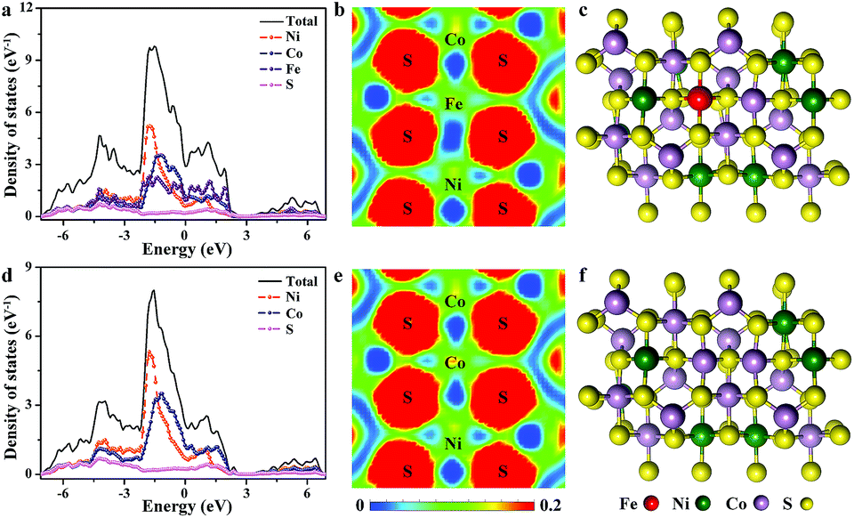 | ||
| Fig. 1 Calculated DOS for (a) Fe-doped NiCo2S4 and (d) NiCo2S4. Electron localization function for (b) Fe-doped NiCo2S4 and (e) NiCo2S4. Crystal structure of (c) Fe-doped NiCo2S4 and (f) NiCo2S4. | ||
Bearing this in mind, a material composed of Fe-doped NiCo2S4 nanosheet layers wrapped on N,S-doped ordered mesoporous carbon (Fe-NiCo2S4@N,S-CMK-3) is prepared. After Fe doping, the Fe-NiCo2S4 nanosheets have higher electronic conductivity and higher ionic liquid electrolyte adsorption enthalpy. The latter is supported by DFT calculations with a lower IL adsorption energy of −4.0 eV for Fe-NiCo2S4 than −3.78 eV for NiCo2S4. Translated to an enthalpy scale, these adsorption enthalpies correspond to roughly 400 kJ mol−1 and the energy gain of EMIM+ ions when adsorbed on such a doping site would correspond to more than 20 kJ mol−1. In addition, the mesopores in N,S-doped mesoporous carbon can lead to additional energy storage contribution due to ordering transitions in the bulk electrolyte as reported recently.17,33 In consequence, Fe-NiCo2S4@N,S-CMK-3 composite electrodes provide a high specific capacitance of 197.8 F g−1 (0–3.5 V) at a scan rate of 2 mV s−1.
Results and discussion
The Fe-NiCo2S4@N,S-CMK-3 material was prepared by a hydrothermal reaction in the presence of the N,S-CMK-3 host which induces nucleation of the sulfide (Fig. S3–S5†). Urea was used as the growth-promoting agent to achieve Fe-NiCo2S4 nanosheets. X-ray diffraction (XRD) patterns of NiCo2S4@N,S-CMK-3 and Fe-NiCo2S4-CMK-3 (Fig. 2a) exhibit comparable profiles. The characteristic XRD reflections located at 17.2°, 26.6°, 31.3°, 38.2°, 50.4°, and 55.1° 2θ can be assigned to the (111), (220), (311), (400), (511), and (440) planes of cubic NiCo2S4 (JCPDS no, 20-0782), respectively.34,35 The comparable pattern after iron doping indicates that doing so does not change the crystal structure of NiCo2S4. SEM images of as-prepared Fe-NiCo2S4@N,S-CMK-3 (Fig. 2b and c) show that the Fe-NiCo2S4 nanosheets have a thickness of ∼10 nm and that they are assembled as a uniform shell around the carbon particles. As revealed by the high-magnification SEM image (Fig. 2c), a lot of open pore volume is present between neighboring Fe-NiCo2S4 nanosheets, which is beneficial for the ionic liquid capture on the surface of the electrode material. The macroporous structure resulting from the assembly of the nanosheets on the surface of the ordered mesoporous N,S-CMK-3 further provides the composite with a hierarchical architecture. The porous structure of Fe-NiCo2S4 immobilized on N,S-CMK-3 is also demonstrated by TEM imaging (Fig. 2d). In agreement with the XRD patterns, the well resolved lattice fringes of Fe-NiCo2S4 nanosheets visible in the HRTEM image (Fig. 2e) display interplane spacings of 0.235 and 0.285 nm, corresponding to the (400) and (311) planes of NiCo2S4. This further reveals the presence of the NiCo2S4 crystal structure after Fe doping. The selected-area electron diffraction pattern (inset in Fig. 2e) shows the polycrystalline structure of Fe-NiCo2S4 nanosheets. Energy dispersive X-ray spectroscopy (EDS) analysis (Fig. 2f) reveals the coexistence of C, N, Fe, Ni, Co, and S in Fe-NiCo2S4@N,S-CMK-3. The content ratio of Ni, Co, S, and Fe corresponds to a Fe0.12NiCo1.66S3.62 stoichiometry. In addition, the loading of Fe-NiCo2S4 nanosheets on N,S-CMK-3 is calculated to be ∼59.5% based on thermal analysis (Fig. S6†).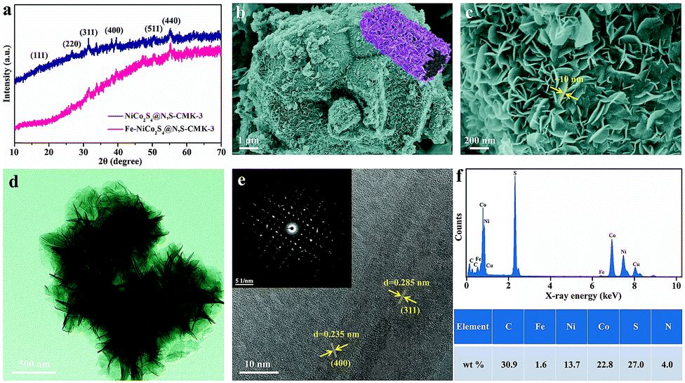 | ||
| Fig. 2 (a) XRD patterns of NiCo2S4@N,S-CMK-3 and Fe-NiCo2S4@N,S-CMK-3. (b and c) SEM images of Fe-NiCo2S4@N,S-CMK-3 at different magnifications. (d) TEM image of Fe-NiCo2S4@N,S-CMK-3, (e) HRTEM image of Fe-NiCo2S4@N,S-CMK-3. Inset: selected-area electron diffraction pattern. (f) EDS spectrum of Fe-NiCo2S4@N,S-CMK-3 and content of different elements. | ||
The nitrogen physisorption isotherms measured at −196 °C and the pore size distributions of N,S-CMK-3 and Fe-NiCo2S4@N,S-CMK-3 (Fig. 3a and b) show that the Brunauer–Emmet–Teller specific surface area (SSA) and the total pore volume of Fe-NiCo2S4@N,S-CMK-3 are 890 m2 g−1 and 1.0 cm3 g−1, respectively. These values are lower than those of N,S-CMK-3 which has a SSA of 1485 m2 g−1 and a pore volume of 1.4 cm3 g−1. Pore size distribution curves of both N,S-CMK-3 and Fe-NiCo2S4@N,S-CMK-3 show their well-developed mesopores with a pore diameter centered at 3–6 nm. The uptake of nitrogen at relative pressures close to p p0−1 = 1 in Fe-NiCo2S4@N,S-CMK-3 indicates the presence of large mesopores or macropores on the external surface area of N,S-CMK-3 which is likely a result of the structure of the Fe-NiCo2S4 nanosheets. The decreased SSA and pore volume for Fe-NiCo2S4@N,S-CMK-3 are mainly due to the coverage of the porous carbon with less porous Fe-NiCo2S4 nanosheets.
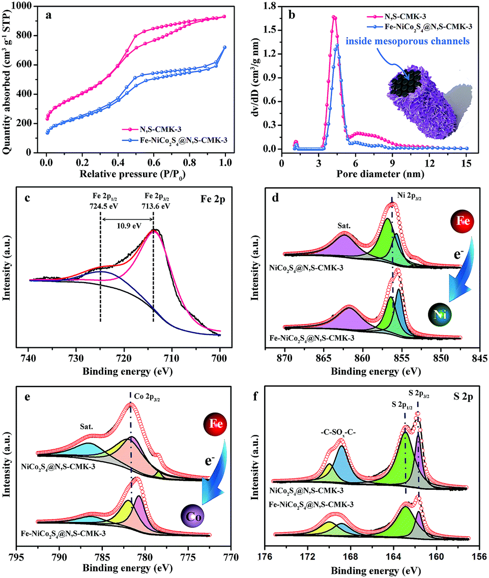 | ||
| Fig. 3 (a) N2 adsorption–desorption isotherms measured at −196 °C and (b) QSDFT pore size distributions of N,S-CMK-3 and Fe-NiCo2S4@N,S-CMK-3. (c) High resolution spectrum of the Fe 2p XPS peak of Fe-NiCo2S4@N,S-CMK-3. High resolution spectra of the (d) Ni 2p3/2, (e) Co 2p3/2, and (f) S 2p XPS peak of NiCo2S4@N,S-CMK-3 and Fe-NiCo2S4@N,S-CMK-3. | ||
An X-ray photoelectron spectroscopy (XPS) survey spectrum (Fig. S7†) provides direct evidence for the presence of C, N, Fe, Ni, Co, and S in Fe-NiCo2S4@N,S-CMK-3. The XPS peaks of Fe 2p3/2 and Fe 2p1/2 appear at 713.6 and 724.5 eV with a peak separation of 10.9 eV (Fig. 3c), indicating the doping of Fe3+ in NiCo2S4.36 Notably, the binding energies of both Ni 2p3/2 and Co 2p3/2 are shifted to lower values after Fe doping by about 0.7 eV (Fig. 3d and e). This indicates strong electronic interactions between Fe and Ni/Co. This enhanced metal–metal interaction is caused by the electronic delocalization from the outer orbitals of Fe atoms, towards neighboring Ni and Co atoms. Consequently, abundant electron-enriched Ni and Co atoms can be produced, which are potential high-energy adsorption sites for ionic liquid ions. The N 1s XPS peak (Fig. S8†) corresponds to pyridine-like nitrogen (N-6, 398.3 eV), pyrrolic-like nitrogen (N-5, 399.2 eV), and graphitic-like nitrogen (N-X, 403.6 eV) doped in the carbon structure. Three peaks can be deconvoluted from the S 2p spectrum (Fig. 3f), which originate from the integration of sulfur anions in Fe-NiCo2S4 and doped sulfur in N,S-CMK-3. The higher pinnacle at 168.9 eV corresponds to the oxidized sulfur forms of –C–SOx–C– sulfone bridges; the lower pinnacles at 162.9 and 161.9 eV are assigned to the S 2p1/2 and S 2p3/2 of thiophene-type sulfur species and anionic S in Fe-NiCo2S4, respectively. The fixed peak positions of S 2p1/2 and S 2p3/2 in both NiCo2S4@N,S-CMK-3 and Fe-NiCo2S4@N,S-CMK-3 indicate unchanged electron distribution around S atoms after Fe doping.
To investigate the electrochemical performance of the hybrid materials and the individual components, two-electrode symmetric supercapacitors are constructed with EMIMBF4 ionic liquid as the electrolyte with a maximum working-voltage window of 3.5 V. As shown in Fig. S9,† the energy storage performance of CMK-3 can be significantly enhanced from a specific capacitance of 47 F g−1 to 111 F g−1 after N,S-doping at a scan rate of 50 mV s−1, which is attributed to the strong surface polarity in the presence of N and S and thus stronger adsorption of ionic liquids. Representative cyclic voltammetry (CV) curves (0–3.5 V) of the Fe-NiCo2S4@N,S-CMK-3, NiCo2S4@N,S-CMK-3, Fe-NiCo2S4@CMK-3, and NiCo2S4 electrodes (Fig. 4a) show quasi-rectangular shapes without distinct redox peaks, indicating the absence of major redox-based (pseudocapacitive/battery-like) processes. Specifically, the specific capacitance of Fe-NiCo2S4@N,S-CMK-3 is calculated to be 197.8 F g−1 at a scan rate of 2 mV s−1, which is much higher than not only that of the NiCo2S4@N,S-CMK-3 electrode (155.2 F g−1) but also that of the Fe-NiCo2S4@CMK-3 electrode (135.9 F g−1). This capacitance enhancement in Fe-NiCo2S4@N,S-CMK-3 likely results from a synergistic effect between stronger polarization of ionic liquid due to the Fe atoms in Fe-NiCo2S4 nanosheets as well as the N and S atoms in N,S-CMK-3. The latter possibly leads to a stronger interaction between the Fe-NiCo2S4 nanosheets and the conductive carbon host as compared to the pristine CMK-3. The poor specific capacitance of bulk NiCo2S4 (73.9 F g−1) results from severe aggregation in the absence of CMK-3 particles (inset image in Fig. 4a) with no notable porosity and poor rate stability. A high specific capacitance of 92 F g−1 can be preserved with a high retention of 46.5% for the Fe-NiCo2S4@N,S-CMK-3 electrode (Fig. S10 and S11†). Its specific capacitance is significantly higher as compared to NiCo2S4@N,S-CMK-3 over the entire range of scan rates applied. Electrochemical impedance spectroscopy (Fig. S12†) demonstrates faster ion transportation in Fe-NiCo2S4@N,S-CMK-3, compared with NiCo2S4@N,S-CMK-3 and N,S-CMK-3. To be noted, the Fe-NiCo2S4@N,S-CMK-3 electrode also displays about 43% higher capacitance compared to the physically mixed electrode of Fe-NiCo2S4 and N,S-CMK-3 powders, demonstrating the synergistic effect between Fe-NiCo2S4 and N,S-CMK-3 compounds with a good interfacial connection (Fig. S13†). No significant loss of capacitance is observed after 5000 cycles (Fig. S14†). There are three advantages of Fe-NiCo2S4@N,S-CMK-3 that can explain its enhanced energy storage performance (Fig. 4b): (1) the ultrathin nanosheets covered on N,S-CMK-3 provide abundant high-energy adsorption sites for IL ions which can be further strengthened by Fe doping (Fig. 4c). (2) The heteroatom-doping in N,S-CMK-3 leads to intimate contact between Fe-NiCo2S4 nanosheets and the highly conductive host. (3) The mesopores in N,S-CMK-3 further contribute to energy storage.
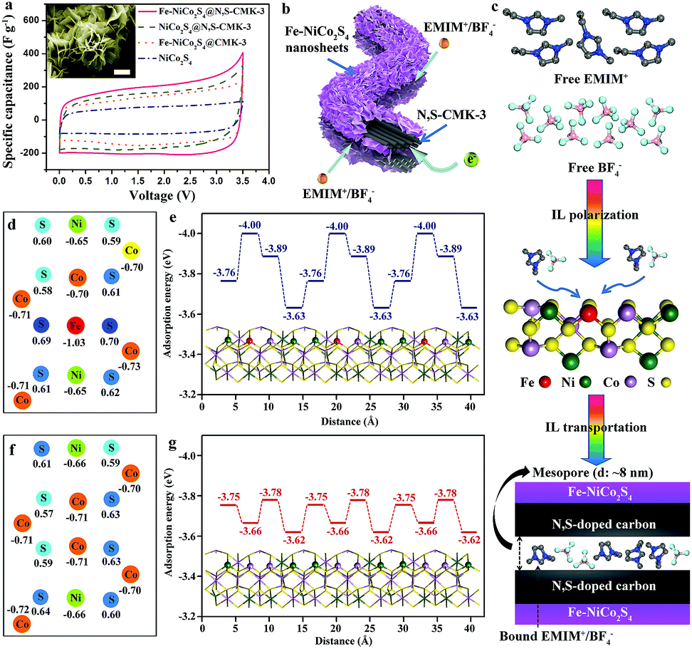 | ||
| Fig. 4 (a) CV curves of Fe-NiCo2S4@N,S-CMK-3, NiCo2S4@N,S-CMK-3, Fe-NiCo2S4@CMK-3, and NiCo2S4 at a scan rate of 2 mV s−1. Inset: SEM image of the NiCo2S4 bulk (scale bar: 2 μm). (b) Illustration of the electron and IL electrolyte transport pathways in Fe-NiCo2S4@N,S-CMK-3. (c) The proposed energy storage mechanism by using Fe-NiCo2S4@N,S-CMK-3 as the electrode for supercapacitors. (d) Calculated net charge of Fe, Ni, Co, and S atoms in an idealized Fe-NiCo2S4 structure. (e) Calculated adsorption energies for Fe-NiCo2S4 by using cation (EMIM+) as an example. (f) Calculated net charge of Ni, Co, and S atoms in an idealized NiCo2S4 structure. (g) Calculated adsorption energies for NiCo2S4 by using cation (EMIM+) as an example. | ||
In order to understand the influence of doped Fe atoms on the charge storage mechanism in more detail, density functional theory (DFT) calculations are applied. Firstly, the calculated net charge (Fig. 4d and f) reveals that the charge distribution in the Fe-NiCo2S4 plane is significantly changed after Fe doping, especially near the Fe domains. As a result, the Fe-NiCo2S4 surface has a much higher affinity, or in other words, a higher adsorption enthalpy for IL ions. Taking EMIM+ as an example here, a lowering of the adsorption energy to −4.00 eV is found (Fig. 4e). This is a much higher adsorption energy as compared to the Ni and Co atoms in the non-doped sulfide. After Fe doping, the adsorption sites over the remaining Co and Ni atoms are also even higher in energy due to the influence of the nearby Fe (Fig. 4g). Therefore, Fe-NiCo2S4 is beneficial for IL polarization, leading to the efficient capture of IL ions on the very surface of Fe-NiCo2S4 nanosheets (Fig. 4c). IL ions within the inner empty space of mesoporous N,S-CMK-3 will further contribute to energy storage.
In order to achieve a higher working-voltage window, however, the key issue before asymmetric supercapacitor (ASC) device fabrication is choosing suitable materials (Fe-NiCo2S4@N,S-CMK-3 and N,S-CMK-3) as positive and negative electrodes, respectively. Firstly, two ASC devices were assembled by using Fe-NiCo2S4@N,S-CMK-3 and N,S-CMK-3 as positive and negative electrodes, respectively. As shown in Fig. S15,† the Fe-NiCo2S4@N,S-CMK-3//N,S-CMK-3 device displays about 94% higher capacitance compared to the opposite N,S-CMK-3//Fe-NiCo2S4@N,S-CMK-3 device, which is due to the unmatched specific surface areas between Fe-NiCo2S4@N,S-CMK-3 (890 m2 g−1) and N,S-CMK-3 (1485 m2 g−1), and different ion sizes between EMIM+ (d ≈ 0.78 nm) and BF4− (d ≈ 0.45 nm). Therefore, Fe-NiCo2S4@N,S-CMK-3 seems to be more suitable to adsorb smaller BF4− ions. In consequence, Fe-NiCo2S4@N,S-CMK-3 has been chosen instead of N,S-CMK-3 as the positive electrode (Fig. 5a and b) in the working-voltage window of the Fe-NiCo2S4@N,S-CMK-3//N,S-CMK-3 ASC device can reach 4 V. Similar to that of the Fe-NiCo2S4@N,S-CMK based symmetric supercapacitor, the ASC device also displays rate-dependent CV characteristics at various scan rates ranging from 2 to 100 mV s−1 (Fig. 5c and S16†) without obvious redox peaks. Fig. 5d presents the galvanostatic charge–discharge curves of the as-fabricated ASC device at different current densities, showing quasi-triangular shapes. Based on the galvanostatic charge–discharge curve, the calculated specific capacitance of the ASC device reaches a value of 48.4 F g−1 based on the total active material of the device. At a high current density of 5 A g−1, the ASC device still has a high capacitance retention of 46.9%. The energy and power densities are the key criteria for practical applicability and are shown in the Ragone plots (Fig. 5f). The energy density of the Fe-NiCo2S4@N,S-CMK-3//N,S-CMK-3 ASC device reaches 107.5 W h kg−1 at a power density of 100 W kg−1 when the working-voltage window is 4 V. In an asymmetric configuration, the supercapacitors can efficiently utilize the multi-dimensional structure of both Fe-NiCo2S4@N,S-CMK-3 and N,S-CMK-3 electrodes.
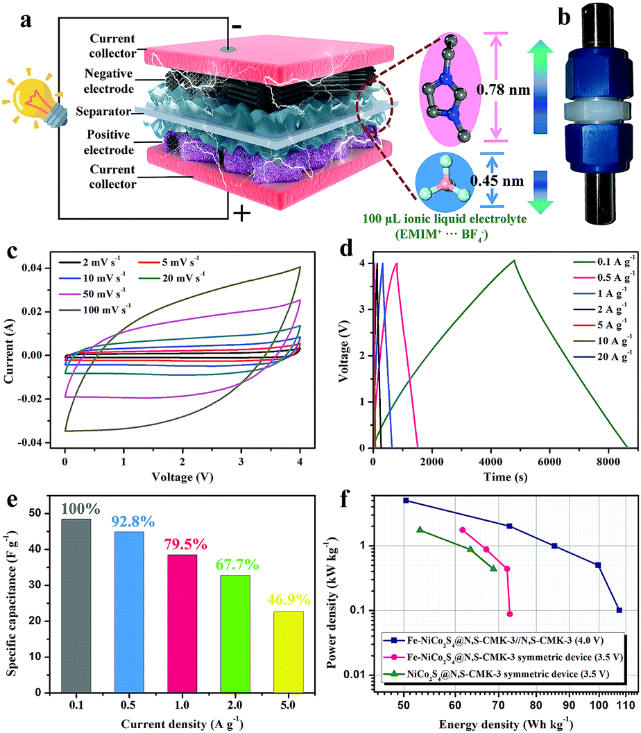 | ||
| Fig. 5 (a) Schematic illustration of an ionic liquid electrolyte-based asymmetric supercapacitor (positive electrode: Fe-NiCo2S4@N,S-CMK-3, negative electrode: N,S-CMK-3, separator: filter paper, current collector: Pt). (b) Photograph of the asymmetric supercapacitor device. (c) The CV curves at various scan rates, (d) galvanostatic charge–discharge curves at various current densities, and (e) specific capacitances of the Fe-NiCo2S4@N,S-CMK-3//N,S-CMK-3 asymmetric supercapacitor device. (f) Ragone plots of different fabricated supercapacitor devices. | ||
Conclusions and outlook
In summary, we have presented a novel design for supercapacitor electrodes by growing iron-doped NiCo2S4 nanosheets on the surface of mesoporous N,S-CMK-3, which delivers a high specific capacitance of 197.8 F g−1 at a scan rate of 2 mV s−1, as well as stable cycling. Its excellent energy storage performance can be attributed to the enhanced ionic liquid coupling and partially delocalized charge in the Fe-NiCo2S4 surface in combination with the mesoporous N,S-CMK-3 structure. Furthermore, the importance of matching multi-dimensional structures and ionic liquid ion sizes in the fabrication of asymmetric supercapacitors has been shown. As a result, the as-assembled ASC device achieves a high energy density of 107.5 W h kg−1 at a power density of 100 W kg−1 with an extended working-voltage window to 4 V when using Fe-NiCo2S4@N,S-CMK-3 and N,S-CMK-3 as positive and negative electrodes, respectively.Experimental
Details of synthetic procedures, characterization and theoretical calculation methods as well as further characterization data can be found in the ESI† of this article.Conflicts of interest
There are no conflicts of interest to declare.Acknowledgements
We gratefully acknowledge financial support by the Max-Planck society and Open Access funding provided by the Max Planck Society.References
- W. T. Gu and G. Yushin, Wiley Interdiscip. Rev.: Energy Environ., 2014, 3, 424–473 CAS.
- P. Simon and Y. Gogotsi, Nat. Mater., 2008, 7, 845–854 CrossRef CAS PubMed.
- D. P. Dubal, O. Ayyad, V. Ruiz and P. Gomez-Romero, Chem. Soc. Rev., 2015, 44, 1777–1790 RSC.
- Y. L. Shao, M. F. El-Kady, J. Y. Sun, Y. G. Li, Q. H. Zhang, M. F. Zhu, H. Z. Wang, B. Dunn and R. B. Kaner, Chem. Rev., 2018, 118, 9233–9280 CrossRef CAS PubMed.
- A. Slesinski, C. Matei-Ghimbeu, K. Fic, F. Beguin and E. Frackowiak, Carbon, 2018, 129, 758–765 CrossRef CAS.
- W. Zong, F. L. Lai, H. J. He, J. R. Feng, W. Wang, R. Q. Lian, Y. E. Miao, G.-C. Wang, I. P. Parkin and T. X. Liu, Small, 2018, 14, 1801562 CrossRef PubMed.
- X. M. Liu, W. J. Zang, C. Guan, L. Zhang, Y. H. Qian, A. M. Elshahawy, D. Zhao, S. J. Pennycook and J. Wang, ACS Energy Lett., 2018, 3, 2462–2469 CrossRef CAS.
- F. L. Lai, G. Y. Zhou, F. Li, Z. H. He, D. Y. Yong, W. Bai, Y. P. Huang, W. W. Tjiu, Y. E. Miao, B. C. Pan and T. X. Liu, ACS Sustainable Chem. Eng., 2018, 6, 3143–3153 CrossRef CAS.
- F. Béguin, V. Presser, A. Balducci and E. Frackowiak, Adv. Mater., 2014, 26, 2219–2251 CrossRef PubMed.
- W. H. Liu, K. Wang, C. Li, X. Zhang, X. Z. Sun, J. W. Han, X. L. Wu, F. Li and Y. W. Ma, J. Mater. Chem. A, 2018, 6, 24979–24987 RSC.
- F. L. Lai, J. R. Feng, R. Y. Yan, G.-C. Wang, M. Antonietti and M. Oschatz, Adv. Funct. Mater., 2018, 28, 1801298 CrossRef.
- F. Zhang, Y. H. Lu, X. Yang, L. Zhang, T. F. Zhang, K. Leng, Y. P. Wu, Y. Huang, Y. F. Ma and Y. S. Chen, Small, 2014, 10, 2285–2292 CrossRef CAS PubMed.
- X. H. Xia, J. Y. Zhan, Y. Zhong, X. L. Wang, J. P. Tu and H. J. Fan, Small, 2017, 13, 1602742 CrossRef PubMed.
- T. Q. Lin, I. W. Chen, F. X. Liu, C. Y. Yang, H. Bi, F. F. Xu and F. Q. Huang, Science, 2015, 350, 1508–1513 CrossRef CAS PubMed.
- D. B. Liu, K. Ni, J. L. Ye, J. Xie, Y. W. Zhu and L. Song, Adv. Mater., 2018, 30, 1802104 CrossRef PubMed.
- J. Li, N. Wang, J. R. Tian, W. Z. Qian and W. Chu, Adv. Funct. Mater., 2018, 28, 1806153 CrossRef.
- R. Y. Yan, M. Antonietti and M. Oschatz, Adv. Energy Mater., 2018, 8, 1800026 CrossRef.
- F. L. Lai, Y. E. Miao, L. Z. Zuo, H. Y. Lu, Y. P. Huang and T. X. Liu, Small, 2016, 12, 3235–3244 CrossRef CAS PubMed.
- L. Liu, L. J. Su, J. W. Lang, B. Hu, S. Xu and X. B. Yan, J. Mater. Chem. A, 2017, 5, 5523–5531 RSC.
- R. Manikandan, C. L. Raj, M. Rajesh, B. C. Kim, G. Nagaraju, W. G. Lee and K. H. Yu, J. Mater. Chem. A, 2018, 6, 11390–11404 RSC.
- F. L. Lai, J. Feng, T. Heil, G.-C. Wang, P. Adler, M. Antonietti and M. Oschatz, Energy Storage Mater., 2019, 20, 188–195 CrossRef.
- S. Sun, J. Lang, R. Wang, L. Kong, X. Li and X. Yan, J. Mater. Chem. A, 2014, 2, 14550–14556 RSC.
- K. Schutjajew, R. Yan, M. Antonietti, C. Roth and M. Oschatz, Front. Mater., 2019, 6, 65 CrossRef.
- Q. D. Chen, J. K. Miao, L. Quan, D. P. Cai and H. B. Zhan, Nanoscale, 2018, 10, 4051–4060 RSC.
- G. X. Zhang, Y. M. Chen, K. Huang, Y. G. Chen and H. B. Guo, Mater. Chem. Phys., 2018, 220, 270–277 CrossRef CAS.
- C. Y. Zhang, X. Y. Cai, Y. Qian, H. F. Jiang, L. J. Zhou, B. S. Li, L. F. Lai, Z. X. Shen and W. Huang, Adv. Sci., 2018, 5, 1700375 CrossRef PubMed.
- W. Y. Li, B. J. Zhang, R. J. Lin, S. Ho-Kimura, G. J. He, X. Y. Zhou, J. Q. Hu and I. P. Parkin, Adv. Funct. Mater., 2018, 28, 1705937 CrossRef.
- X. Han, K. Tao, D. Wang and L. Han, Nanoscale, 2018, 10, 2735–2741 RSC.
- K. Tao, X. Han, Q. Ma and L. Han, Dalton Trans., 2018, 47, 3496–3502 RSC.
- K. Tao, X. Han, Q. Cheng, Y. Yang, Z. Yang, Q. Ma and L. Han, Chem.–Eur. J., 2018, 24, 12584–12591 CrossRef CAS PubMed.
- J. Q. Xu, X. D. Li, W. Liu, Y. F. Sun, Z. Y. Ju, T. Yao, C. M. Wang, H. X. Ju, J. F. Zhu, S. Q. Wei and Y. Xie, Angew. Chem., Int. Ed., 2017, 56, 9121–9125 CrossRef CAS PubMed.
- K. Xu, P. Z. Chen, X. L. Li, Y. Tong, H. Ding, X. J. Wu, W. S. Chu, Z. M. Peng, C. Z. Wu and Y. Xie, J. Am. Chem. Soc., 2015, 137, 4119–4125 CrossRef CAS PubMed.
- M. Antonietti, X. D. Chen, R. Y. Yan and M. Oschatz, Energy Environ. Sci., 2018, 11, 3069–3074 RSC.
- Y. S. Wu, X. J. Liu, D. D. Han, S. W. Niu, Y. F. Xie, J. Y. Cai, S. K. Wu, J. Kang, J. B. Zhou, Z. Y. Chen, X. S. Zheng, X. H. Xiao and G. M. Wang, Nat. Commun., 2018, 9, 1425 CrossRef PubMed.
- X. T. Feng, Q. Z. Jiao, H. R. Cui, M. M. Yin, Q. Li, Y. Zhao, H. S. Li, W. Zhou and C. H. Feng, ACS Appl. Mater. Interfaces, 2018, 10, 29521–29531 CrossRef CAS PubMed.
- Z. Cai, D. J. Zhou, M. Y. Wang, S. M. Bak, Y. S. Wu, Z. S. Wu, Y. Tian, X. Y. Xiong, Y. P. Li, W. Liu, S. Siahrostami, Y. Kuang, X. Q. Yang, H. H. Duan, Z. X. Feng, H. L. Wang and X. M. Sun, Angew. Chem., Int. Ed., 2018, 57, 9392–9396 CrossRef CAS PubMed.
Footnote |
| † Electronic supplementary information (ESI) available: Optimized crystal structures, schematic illustration, TEM images, XRD patterns, TGA profiles, XPS spectra, cyclic voltammograms, galvanostatic charge–discharge curves, Nyquist plots, and cycling stability. See DOI: 10.1039/c9ta06250e |
| This journal is © The Royal Society of Chemistry 2019 |