
Liquid metal core–shell structures functionalised via mechanical agitation: the example of Field's metal†
Shuhada A.
Idrus-Saidi
a,
Jianbo
Tang
 a,
Mohammad B.
Ghasemian
a,
Jiong
Yang
a,
Jialuo
Han
a,
Nitu
Syed
b,
Torben
Daeneke
b,
Roozbeh
Abbasi
a,
Pramod
Koshy
c,
Anthony P.
O'Mullane
d and
Kourosh
Kalantar-Zadeh
*a
a,
Mohammad B.
Ghasemian
a,
Jiong
Yang
a,
Jialuo
Han
a,
Nitu
Syed
b,
Torben
Daeneke
b,
Roozbeh
Abbasi
a,
Pramod
Koshy
c,
Anthony P.
O'Mullane
d and
Kourosh
Kalantar-Zadeh
*a
aSchool of Chemical Engineering, University of New South Wales (UNSW), Sydney, NSW 2052, Australia. E-mail: k.kalantar-zadeh@unsw.edu.au
bSchool of Engineering, RMIT University, Melbourne, VIC 3000, Australia
cSchool of Materials Science and Engineering, University of New South Wales (UNSW), Sydney, NSW 2052, Australia
dSchool of Chemistry, Physics and Mechanical Engineering, Queensland University of Technology (QUT), Brisbane, QLD 4001, Australia
First published on 16th July 2019
Abstract
Exploring the concept of liquid processing and solidification of low melting point alloys can provide new routes for the creation of functional micro and nanoparticles. Here we show that it is possible to produce particles of Field's metal (an alloy of bismuth 32.5 wt%, tin 16.5 wt% and indium 51 wt%) in a one-step mechanical agitation (ultrasonication) procedure. The synthesis takes place just above 62 °C, the melting point of Field's metal, and results in the formation of low-dimensional particles after solidification. It is demonstrated that the sonication process produces nearly spherical core–shell metal–metal oxide heterostructures. Classic alloy-related defects, in the forms of grain boundaries and edge locations, emerge after the solidification. We show that by the incorporation of Ag, either using direct alloying or an Ag salt precursor during the sonication process, this metal appears in the core of the metal–metal oxide heterostructures. Interestingly, the modification of particles with Ag gives specific selectivity for the degradation of two typical azo dyes. The one-step low-temperature synthesis and solidification procedure, presented in this work, can be readily extended for designing catalysts or other functional materials with desired specificity and selectivity.
Introduction
Liquid metals feature metallic properties and peculiar surface activities which are intrinsically different from those encountered in other liquids. Recently, the emerging non-toxic room-temperature gallium-based liquid metals have drawn extensive interest due to their peculiar physical and chemical properties such as excellent thermal and electrical conductivity,1–3 tunable fluidity/rheology,4–6 controllable surface chemistry and compatibility with various materials for improved functionalities.7–11 These properties of liquid metals have drawn growing interest in liquid-metal-enabled catalysis, flexible electronics, smart actuators/sensors, thermal fluidics/microfluidics, microelectromechanical systems and biomedical applications.12–16Mixing two or more metals together, which can potentially reduce the melting point (MP) of the system, is a well-known strategy to access low MP substitutional alloys. The incorporation of different metals in alloys can increase the entropy and the number of chemical active species, which, besides decreasing the melting point, also leads to more desirable pysicochemistry properties for various applications.17–19 Moreover, in many chemical processes, multimetallic catalysts have been shown to give rise to improved performance.20–25 However, while the functionalities of liquid metals and their surface modifications have been shown to have great properties for catalysis, what they offer for synthesis of catalytic materials and also after solidification phase have not been investigated.
Besides its technological advantages, the utilisation of liquid metal alloys is associated with fundamental aspects of multi-metal systems. Both the core and surface of liquid metal alloys, where the latter features atomic-scale activities, require further study as satisfactory understanding has not yet been achieved. Recent discoveries achieved through touch-printed oxide layers from different liquid metal alloys revealed that specific components inside a liquid alloy systems are oxidised near the interfacial boundaries and that selective oxidation is thermodynamically driven by the Gibbs free energy of oxidation.26 The awareness of such selective oxidation processes, and being able to actively control the core and surface of liquid metals will enable applications in advanced electronics, optics, and catalysis.27
Phase separation is a surface and core inter-related phenomenon encountered when liquid metal alloys are solidified. Due to the differences in atomic structures, solidified alloys can have separated phases and/or intermetallic phases. The solidification of alloys is triggered by nuclei formation, the successive growth of which leads to the redistribution of different phases. Therefore, the solidification of a homogenous liquid metal alloy creates local compositional differences, which can cause drastic changes in the physicochemical properties of the alloys.28,29 In addition, this solidification process induces stress during crystal formation that can promote defects and favour catalytic processes.30 It can thus be inferred that materials produced with liquid metal alloys can possess intrinsic differences from other methods due to both selective surface oxidation and phase separation processes.
Despite the development of different types of low-melting-point alloys, such as Rose's metal (alloys of bismuth 50 wt%, lead 25 wt%, and tin 25 wt%, MP: 98 °C), Wood's metal (alloy of bismuth 50 wt%, lead 26.7 wt%, tin 13.3 wt%, and cadmium 10 wt%, MP: 70 °C), Field's metal (alloy of bismuth 32.5 wt%, tin 16.5 wt%, and indium 51 wt%, MP: 62 °C), knowledge regarding their solidification remains unexplored, which could be advantageous for various applications which date to remain unknown. The surface oxidation of liquid metal's upper surface can form a delicate semiconductor oxide shielding on its metallic core. Therefore, surface-oxidised liquid metal particles are by nature tiny metal–semiconductor heterostructures, which are promising functional materials for catalysis.31,32
One advantage of processing alloys in their liquid state is that a high surface-to-volume ratio can be directly achieved using readily accessible physical approaches like mechanical agitation, which, unlike chemical methods, requires low energy and does not suffer from hazardous precursors and by-products. Regarding liquid metal processing, alloys of post-transition metals are in general more feasible since transition metals usually have a high MP (except the zinc group). However, we do note that high-melting-point transition metals can also be transformed into low-melting-point post-transition alloy systems33 and even small amounts of such ‘ingredients’ can play a big role on the functionality of the end products due to the migration of certain types of metals to the surface.34 Many post-transition metals and their compounds are catalytically active35–37 while they also exhibit intriguing conducting behaviour in response to external thermal, electrical, and photonic excitations.38
Ultrasonication, as a type of mechanical agitation, has already been applied to post-transition alloys, room-temperature gallium-based liquid metals, for microfluidics, drug delivery, and photocatalysis applications.39–41 It should be noted that micro/nano particles of gallium-based alloys are still liquid at room-temperature, which therefore eliminates the observation of any phase separation effect. The search for liquid metal alloys amenable to ultrasonication while also exhibiting phase separation at room temperature narrows down to low-melting-point alloys that melt at moderately elevated temperatures. Among all the available candidates, Field's metal, is a suitable candidate as it is lead and cadmium free which could be promising for various future applications without any toxicity implications.
In this work, we investigate the ultrasonication of Field's metal (FM) at slightly elevated temperature and solidify it to investigate the fundamental selective oxidation and phase separation of the ternary alloy system at the micro/sub-micro scale. We investigate and elucidate how these processes impose structural and compositional influences on the obtained particles. We also introduce a fourth metallic phase silver (Ag) to the ternary Field's metal system via two different routes and study the interaction of Ag with the Field's metal. Among noble metals, Ag is chosen in this study due to its known properties in catalytic reactions, synergy with the elemental constituents of Field's metal, and its reasonable cost in comparison to other candidates such as gold and platinum.42 The photocatalytic activity of the core–shell structured particles produced by one-step sonication is further examined through dye degradation. The differences in structures and compositions of these Field's metal and Field's metal-based particles, resulting from different sample preparation routes, give rise to distinct photocatalytic activities towards different types of dyes.
Experimental
Materials
Indium, (In, beads of 2–3 mm, 99.9%), tin (Sn, popcorn flakes, 99.9%), bismuth (Bi, shots, 99.9%) were purchased from Rotometals, USA, and silver powder (5–8 μm, 99.9%) was purchased from Sigma-Aldrich. Silver nitrate (AgNO3, 99.5%) was obtained from Chem-Supply Pty Ltd. The model dyes, Congo red (M.W. = 696.66) and methylene blue (M.W. = 319.85), were acquired from Sigma Aldrich.Sample synthesis
Bismuth (32.5 wt%, weight percentage), indium (51 wt%), and tin (16.5 wt%), mixed inside glass containers, were melted in a tube furnace (TF55030C-1, Thermo Scientific) at 300 °C for 3 hours to the prepare the bulk FM. As presented in Fig. 1, the obtained bulk FM was sonicated at 70 °C to prepare the particle samples. This was realised by sonicating the liquid FM (probe sonicator, VCX 750, Sonics & Materials, Inc.) at an elevated temperature with the assistance of a hotplate for 90 min in water (70 mL). Modification to the sample preparation was made by two different routes: one was achieved by sonicating 1 g of FM in a AgNO3 aqueous solution (1 mM and 5 mM, 70 mL of AgNO3) and the other was performed by pre-loading 1 wt% Ag particles to the parent FM and grinding them in a glove box (MB-Labstar 1200/780, H2O/O2 <1 ppm) and sonicating 1 g of the material in water (70 mL). After the sonication, the particle-containing solution was centrifuged (CR4000 centrifuge, Thermoline Scientific) at 8000 rpm for 10 min to remove larger particles. The sample solutions were further dried at 70 °C to remove the remaining water. Another sample was also made and compared by annealing the FM particles for 1 hour at 500 °C in atmospheric air.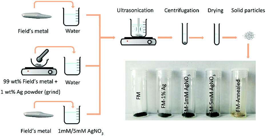 | ||
| Fig. 1 Schematic representation of the step-by-step experimental procedure for preparing the FM particles. Silver is incorporated into the FM via two different methods: alloying and sonicating. | ||
Sample characterisation
The morphology and element distribution of the FM-based samples were characterised by field-emission scanning electron microscopy (FE-SEM, the Nova Nano SEM 450 and 230) and transmission electron microscopy (TEM, Philips CM200, coupled with a Bruker Silicon drift detector (SDD)-Energy-dispersive detector (EDS) EDS detector system). A X'pert Multipurpose X-ray Diffraction (MPD) system (λ = 1.5418 Å, Cu Kα radiation) was utilised to analyse the crystallographic structures of different phases of the samples. Raman spectroscopy (inVia Raman Microscope, RENISHAW, 532 nm laser source) was applied to identify vibrational modes and the UV-Vis absorption spectra of the samples were also measured (Cary 5000 UV-Vis-NIR Spectrophotometer, Agilent Technologies) to access the optical band gap of the materials. Surface chemical analysis was acquired by using an X-ray photoelectron spectroscopy (XPS, Thermo Scientific). The samples were scanned with a monochromic Al Kα X-ray source with a pass energy of 100 kV. Mott–Schottky measurements were conducted in a conventional three-electrode cell using a CHI 760D electrochemical workstation (CH Instrument Co.). The system consisted of an Ag/AgCl (in 3 M NaCl) reference electrode, a gold counter electrode, and a sample-coated copper tape as the working electrode. The apparent area of the working electrode was 1 cm2. Na2SO4 solution (0.1 mol L−1) was used as the electrolyte. Nitrogen was purged into the solution during the measurements. The measurements were performed at three frequencies of 0.5, 1 and 2 kHz using sinusoidal signals of the same amplitude (5 mV). The absolute electrode potential, EAg/AgCl for the system was −4.669 V. Differential scanning calorimetry (DSC) measurements were conducted using Q20 DSC (TA Instruments) at temperature range between 0 to 100 °C at constant rate of cooling and heating (10 °C min−1). Thermodynamic phase diagram was calculated using FactSage Thermochemical Software and Databases.43Photocatalytic experiments
The photocatalytic performance of the synthesised FM-based photocatalysts was evaluated through the degradation of two types of azo dyes: Congo red and methylene blue under simulated solar irradiation. The characteristic absorbance peak at 500 nm and 664 nm for Congo red and methylene blue, respectively, were used for calculating the degradation rates. The degradation rates of the two dyes with the presence of catalyst were investigated under simulated solar irradiation (one Sun) for 120 min (11002, Abet Technologies, Inc.). During a typical test, the photocatalyst sample was resuspended in water to a final concentration of 0.2 mg L−1 and 1.65 mL of the suspended photocatalysts was added into 2 mL of dyes (1.44 × 10⁻⁵ mol L−1 Congo red and 3.13 × 10⁻⁵ mol L−1 methylene blue). The solution was then irradiated under the solar simulator and at the same time stirred at 400 rpm. The absorbance of the sample solution was measured using UV-Vis to determine the degradation rate every 20 min.Results and discussion
Particle size distribution
The SEM images of the particle samples prepared by different procedures are presented in Fig. 2a–e. After the ultrasonication and post processing steps, namely cooling, centrifugation, and drying, the obtained solidified FM particles are found to be of micro/sub-micro sizes, featuring near-spherical configurations.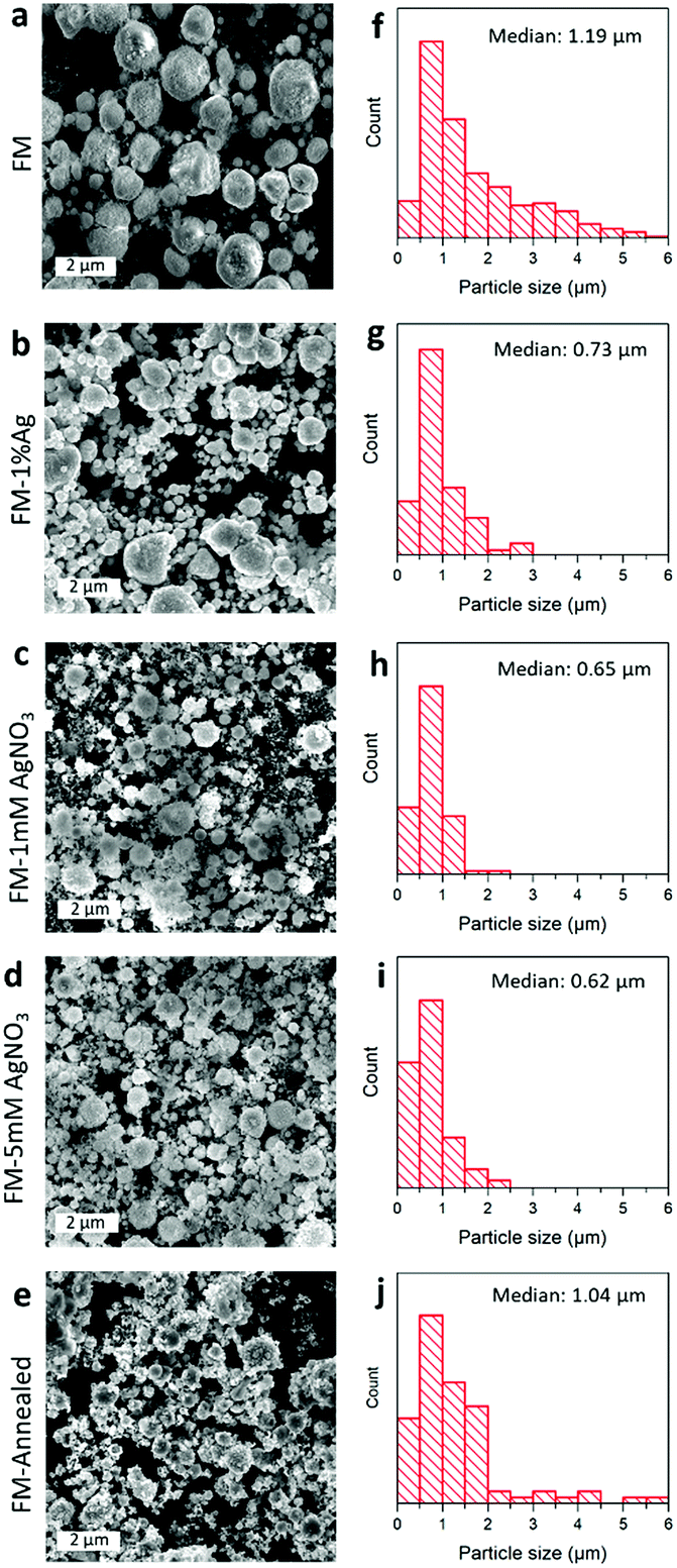 | ||
| Fig. 2 (a–e) SEM images of different FM-based particles prepared by the ultrasonication method in this study and (f–j) their size distribution: (a, f) FM particles, (b, g) FM particles prepared with 1 wt% Ag powder, (c, h) FM particles prepared with 1 mM AgNO3, (d, i) FM particles prepared with 5 mM AgNO3 and (e, j) annealed FM particles. | ||
As demonstrated in Fig. 2f–j, the size distributions show that the as-synthesised FM particles, with no AgNO3 treatment and Ag incorporation, are about 1 μm in diameter. However, the Ag-incorporated samples in general are smaller, either through pre-loading of Ag powder or adding Ag ions during the ultrasonication process. The change in the particle size is thought to be caused by the formation of an Ag-containing liquid core (as will be discussed further in the “Element distribution” section). The presence of Ag in the liquid core increases the entropy of the alloy, which in turn loosens the attractive forces within the liquid alloy, allowing more effective sonication and hence smaller particle formation.44 Furthermore, a comparison between the sample before (Fig. 2f) and after (Fig. 2j) annealing shows that the particle size is not significantly altered by the process. However, their morphologies seem to have lost their roundness, and more flakes are seen to be covering their surfaces.
Crystallographic structures
Interestingly, the XRD results in Fig. 3 show that the particles prepared using the ternary FM have binary BiIn2 and Sn0.8In0.2 as the metallic phases, which indicate that phase separation occurs during the solidification of the liquid FM.45,46 Very importantly, it can be inferred from the XRD peaks of different samples that introducing Ag into FM affects the phase separation process, leading to the formation of different binary metallic phases such as Bi0.8In0.2 and BiIn. The XRD results also reveal that the samples are oxidised after sonication and that this oxidation process is quite selective.26 In the FM system, containing Bi, In, and Sn, indium is found to be preferentially oxidised in all samples and transformed into its hydroxide In(OH)3 since the sonication process is conducted in water. This agrees with previous works that the oxide, which has the highest reduction Gibbs free energy, migrates to the surface and dominates the oxidation process.26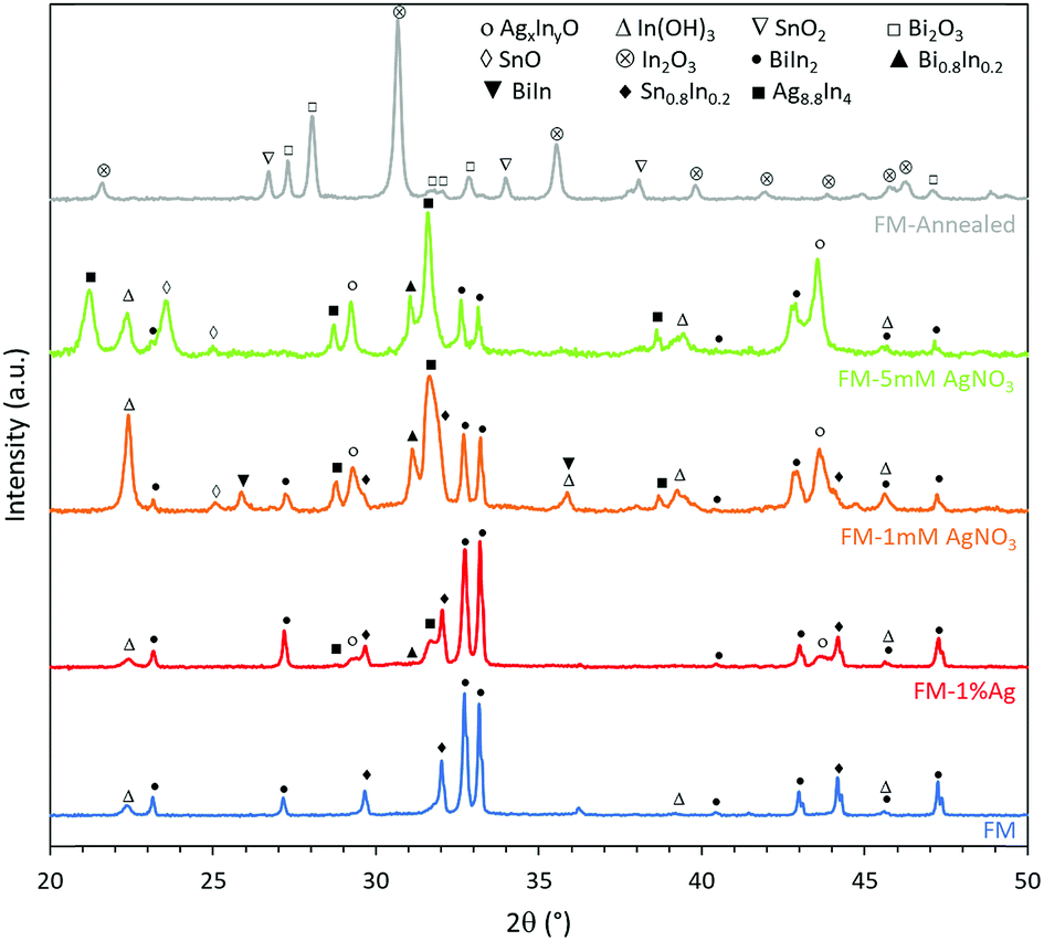 | ||
| Fig. 3 XRD patterns of different samples showing their phase separation and selective surface oxidation. Adding Ag to the FM affects both processes. The reference code of the powder diffraction files (PDFs) used to match the patterns are: In(OH)3 04-008-9898, SnO2 04-008-8133, Bi2O3 00-022-0515, SnO 98-006-0619, In2O3 03-065-3170, BiIn2 04-007-9946, Bi0.8In0.2 04-003-1497, BiIn 98-061-6705, Sn0.8In0.2 04-011-9029, and Ag8.8In4 04-004-4755. | ||
Noteworthily, adding a foreign Ag phase to the system also changes the oxidation process, in particular for samples prepared in the AgNO3 solution during the ultrasonication process. For instance, Ag combines with In to form Ag8.8In4, and additionally, the oxidation of Sn begins to take place through the formation of SnO, as can be seen from the sample sonicated in 5 mM AgNO3. However, when the sample is prepared using incorporated Ag0, the intensity of Ag8.8In4 peaks is lower compared to samples prepared with AgNO3, indicating less incorporation of silver into the FM. Therefore, introducing Ag as ions during the ultrasonication process produces liquid metal particles with supersaturated Ag, considering that the eutectic alloy of FM with Ag occurs at less than 1% Ag, which is implemented in the directly alloyed sample. After the incorporation of Ag, another two peaks emerge at 2θ = 29.5° and 43.5° and increase in their intensity when more Ag is added. We associate the appearance of these not previously reported peaks, to the formation of AgxInyO and discuss them further later. We hypothesise that Ag forms a binary oxide compound phase, due to the higher affinity of Ag with In in comparison to Bi and Sn. After annealing the FM particles, they are found to be further oxidised to form In2O3, SnO2 and Bi2O3.
Thermal analysis
DSC analysis was conducted to further confirm the eutectic composition of the samples and their phase separation during solidification. As can be observed from the DSC curves of the bulk Field's metal (Fig. S3a†) and Field's metal particles (Fig. S3b†), both of them display similar peak at the melting temperature of ∼62 °C during the melting cycles, which proves that the samples possess the behaviour of eutectic system. The main difference between the bulk sample and the particle sample is that the latter shows larger peak width during both melting and solidification. This means that, different from the bulk samples, the existence of a large amount of small particles in the sonicated sample makes its crystallisation process happen over a wider temperature range. This is caused by the existence of individual particles of different particle sizes inside the sample. Moreover, the particle sample after ultrasonication shows two broad solidification peaks at a lower temperature in comparison to that of the bulk sample due to supercooling effect. These two exothermic effects at around 30 °C and 40 °C may feature two crystallisation events which can be attributed to phase separation.47 It is important to consider supercooling effect that brings down the solidification temperature from ∼62 °C to ∼57 °C during solidification. A similar trend is also seen in the sample with incorporated 1 wt% Ag (Fig. S3c and d†).Surface composition characterisation
The XPS technique, which is more sensitive for surface composition analysis, is further utilised to characterise the samples. As can be seen from Fig. 4, the surface of the particles for all samples contains oxides of Sn, Bi and In. The peaks in the Sn 3d region (486.2 eV), Bi 4f region (158.7 eV) and In 3d region (444.5 eV) were associated with SnO2/SnO (the 3d peaks of SnO2 and SnO nearly overlap each other), Bi2O3, and In2O3, respectively.48–50 When samples are prepared using AgNO3, a peak at 367.3 eV is seen in the Ag 3d region, which can be assigned to AgxInyO with possibly x + y = 2 with possibly Ag as the dominant metal.51,52 The peak intensity in the Ag 3d region is more intense for the sample treated with 5 mM AgNO3 in comparison to the 1 mM AgNO3 sample. This change clearly shows that the concentration of AgNO3 significantly influences the Ag content on the particles surface. However, Ag oxides are not identifiable by XPS when the sample is fabricated by the direct alloying of FM with Ag. This is indeed in line with the XRD results which show that the intensity of the Ag8.8In4 peaks for the sample prepared using Ag0 is weaker in comparison with the sample prepared using a AgNO3 solution. In brief, incorporating Ag into FM by using AgNO3 as a precursor adds more silver into the particles in contrast to mechanically grinding and alloying Ag0 into FM. It is possible that the precursor supersaturates the particles and this matter is discussed later.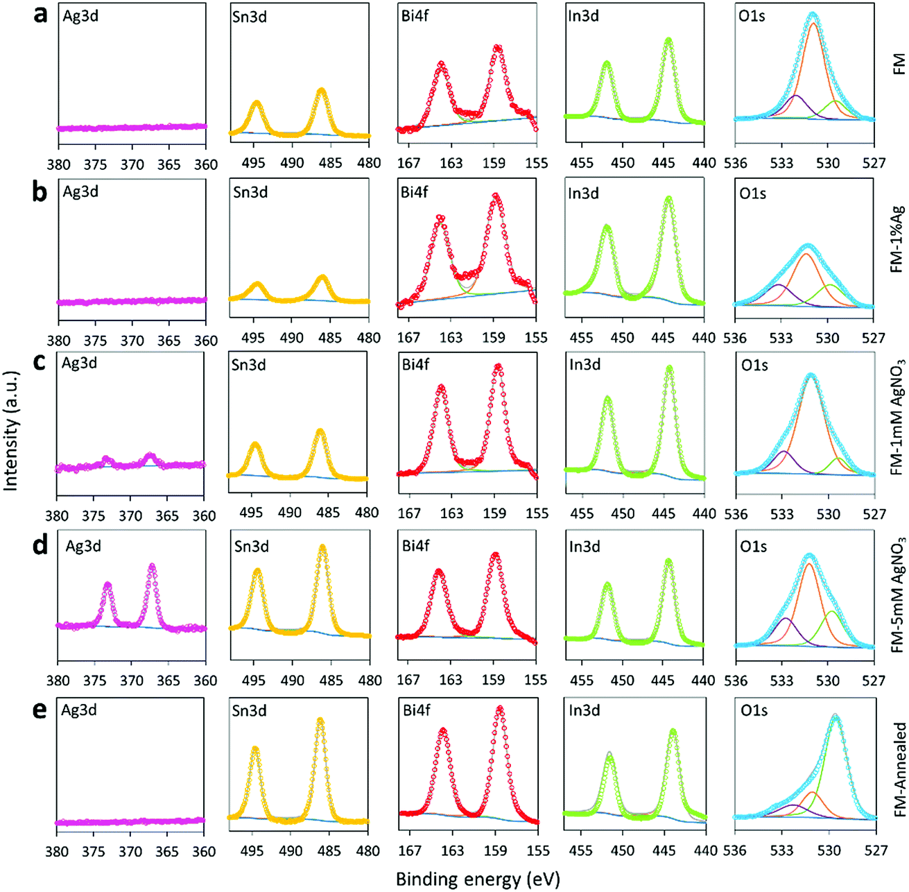 | ||
| Fig. 4 XPS spectra of the Ag 3d, Sn 3d, Bi 4f, In 3d and O 1s regions for: (a) FM, (b) FM-1% Ag, (c) FM-1 mM AgNO3, (d) FM-5 mM AgNO3 and (e) FM-annealed. | ||
The O 1s peaks around 531 eV confirm that the as-prepared samples mainly contain hydroxide (e.g., In(OH)3) on the particle surface and the dehydration of the hydroxide during the annealing process gives rise to an intensity increase of the O 1s oxide peak below 530 eV.53
TEM and elemental analysis
The TEM-EDS data show that the particles typically have a core–shell heterostructure with distinct element distributions (Fig. 5). The cores of the particles are occupied by all the elements of the FM, namely, Bi, In, and Sn. However, only In and Sn element are detected on the shells of the particles. Interestingly, Bi is seen to exist only in the cores as the area covered by Bi is found to be smaller when compared to that covered by In and Sn. Irrespective of the silver source, Ag is found to overlap with In in the core region (Fig. 5b–d). This local elemental distribution is in agreement with the indexed XRD pattern in Fig. 3, where Ag and In bind together to form Ag8.8In4. We observed the presence of Ag8.8In4 clusters on the surface and also in the core of the particles when the samples are prepared using AgNO3. This is understandable since Ag and In do not form intermetallic phases.54 However, these clusters were not seen after direct alloying of the sample with 1 wt% Ag. Evidently, treating particles during sonication with AgNO3 results in the supersaturation of the core with Ag and as a result, natural separation of bimetallic Ag8.8In4 occurs.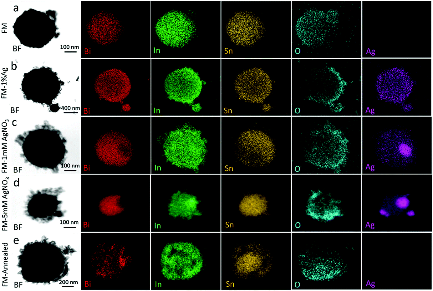 | ||
| Fig. 5 TEM–EDS mapping of the particle samples: (a) FM, (b) FM-1% Ag, (c) FM-1 mM AgNO3, (d) FM-5 mM AgNO3 and (e) FM-annealed. | ||
Altogether, there is no apparent difference between the particles made from Ag ion reaction, in very low concentration of the precursor, and the sample made from direct Ag alloying. However, when more Ag is added to the particles, using the Ag ion reaction method, the cores of the particles become quickly saturated with Ag. In this case, regions of pure Ag emerge within the particles. This is understandable as the eutectic alloy Field's metal becomes saturated with Ag at less than 1 wt%. Any added Ag more than this is phase separated.
The core–shell heterostructure is formed (Fig. S1†) during the ultrasonication process since the selective oxidation of the liquid FM droplets takes place on the surface. It has been shown that the oxidation of liquid metal forms two-dimensional layers since the liquid metal surface is perfectly smooth.26,55–57
Therefore, the progressive and selective oxidation of the FM in the current case produces sheet structures on the particle surface. These flakes which form the shells are expected to be thin and porous since they are stacked atomic layers. The results also mean that the liquid metal ultrasonication method directly produces particles with an oxide shell and metallic core, that is, particles with potential Schottky heterostructures.58,59
The typical core–shell heterostructure of the ultrasonicated particles is demonstrated in Fig. 6a and b. The high-resolution TEM (HRTEM) image in Fig. 6c shows that although the particles are of micro- or sub-microscale, their shell consists of few-nanometre crystal structures, featuring mis-orientated grains and dense grain boundaries, while the flakes are polycrystalline in structure. Apart from the aforementioned atomic oxidation of the liquid metal, the abrupt crystallisation of the particles, during the cooling process, as well as the high entropy of the trimetallic system resulted from the mixing of different species, is also expected to promote the formation of highly granular structures.30 As can be seen in Fig. 6c, and its selected area diffraction pattern shown in the inset, Sn0.8In0.2, BiIn2 and In(OH)3 can be identified.
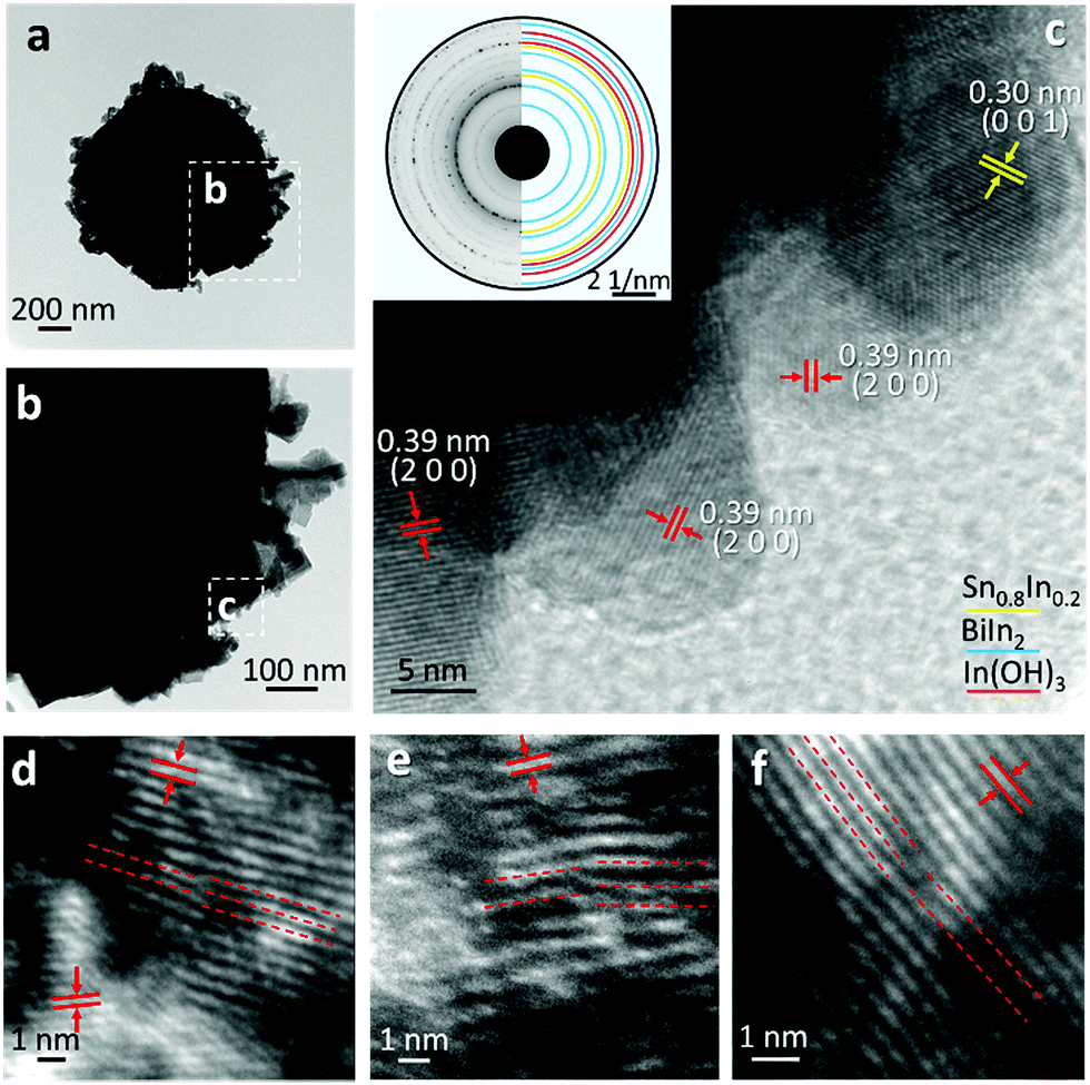 | ||
| Fig. 6 (a) Bright field TEM image of a core–shell structured particle. (b) Magnified view of (a) showing the flake structures of the shell. (c) Further magnified view of (c) showing small grains on the particle surface with inset of SAED pattern (d-f) Edge dislocations identified on the lattice structures. The red lines are drawn to indicate the insertion of an atomic plane at each dislocation site. | ||
The HRTEM images in Fig. 6d–f further highlight the frequently observed one-dimensional defects, edge dislocations, in the samples. Since it is well established that crystal defects can serve as active sites during chemical reactions, the presence of small-scale grains and edge dislocations in the particles is expected to have significant influence on their catalytic activities.
Raman spectra
The Raman spectra of the samples in Fig. 7 are in agreement with the XRD and XPS results in that the sample surface is rich in the selectively oxidised indium product, In(OH)3, which gives rise to a Raman mode at approximately 306 cm−1.60,61 The samples prepared with AgNO3 solution and Ag direct alloying show a broad peak centered at 530 cm−1 which is assigned to the two zone-centre infrared active phonons of AgxInyO with x possibly closer to 2.62,63 It again can be inferred from the Raman spectra that compared to directly adding Ag0 into the FM, the samples prepared with AgNO3 solution have more intense Ag signatures.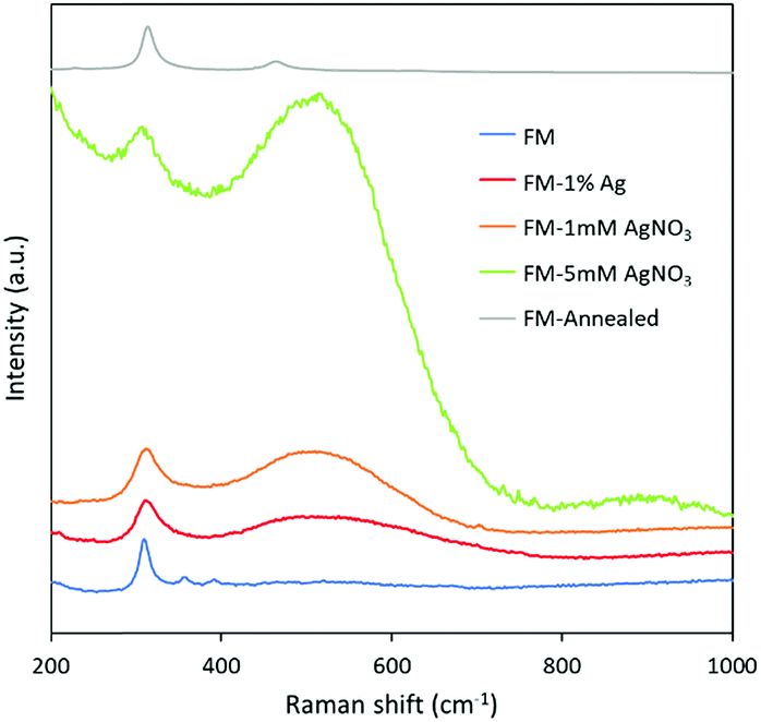 | ||
| Fig. 7 Raman spectra of the samples prepared in this study. | ||
Overall description of particles
Based on the characterisation using XRD, XPS, TEM, EDS, HRTEM and Raman spectroscopy, it appears that the core of particles made from Field's metal consist of intermetallic phases of Bi–In and Sn–In. Phase separation is a process depending on the intrinsic properties of alloy systems. As can be seen from the XRD of the particle samples, when the ternary Field's metal system (Bi–In–Sn) is sonicated and then cooled down from its liquid state, intermetallic phases form between Bi–In and In–Sn. However, no intermetallic phase between Bi–Sn are observed due to the nature of the Bi–Sn system.54 When Ag is introduced to the particles, another binary metallic phase arises which is Ag–In. The appearance of these metallic phases within the particles proves that phase separation takes place during solidification which contributes to the formation of the stable core–shell heterostructure.In addition, the particles are partially oxidised after ultrasonication and the oxidation process is perceived to be selective. Flakes (oxide layer) are evolved around the core of the particles due to this oxidation process, which consist of mainly binary oxide compound of In2O3 and Sn2O. A thermodynamic phase diagram of the Bi–Sn–In–O system was also calculated and the provided in Fig. S4† to present the oxidation process of the particles. It can be seen from the phase diagram that, under our experimental conditions (temperature 70 °C),64 the tendency of oxidation of the ternary Bi–In–Sn alloy follows the order of In2O3 > SnO2 > Bi2O3. Such thermodynamic assessment is in accordance with the XRD results that In2O3 and SnO2 were mainly formed after the sonication process. It is important to consider that In2O3 adapt the hydrated form of In(OH)3 (as revealed by Raman spectroscopy), since the experiment is performed in aqueous environment. It also agrees with the TEM-EDS mapping that In and Sn oxides compose the majority of the surface of the particles. Other oxides that are also shown to exist according to the XPS analysis, appear to be in trace concentrations in comparison to the main oxides detected by XRD and TEM-EDS.
The variations of atomic size and crystal structure of different elements in Field's metal (Bi–In–Sn) normally lead to the formation of crystallographic defects during solidification of the particles. The nuclei develop and grow to form crystals which is unlikely to fit with each other, therefore, give rise to different types of defects. Noteworthily, in this work, one-dimensional (dislocations) and two-dimensional (grain boundaries) defects are observed from the HRTEM images which can be a great influence in the catalytic activity of the Field's metal system. These crystal defects exist in both the core and the shell of the solidified particles.
XPS valence spectra, optical bandgap, Mott–Schottky and energy band diagram
The valence band spectra of the samples were assessed using XPS (Fig. 8). The spectra exhibit the presence of trap states in all samples and the values acquired from the plots indicate the difference in energy between the Fermi level and the valence band minimum. The trap states in all samples do not show significant differences with the lowest intensity belonging to the sample that is prepared by alloying Ag0 into the FM system. Considering this observation, any difference in the catalytic activity of the samples should not originate from the presence of trap states.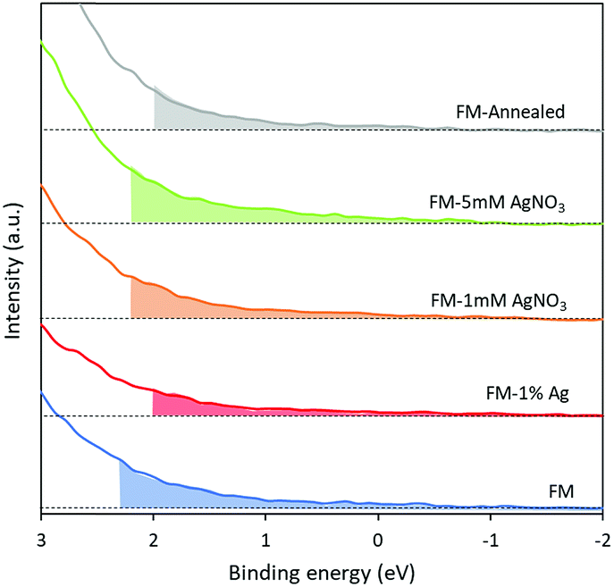 | ||
| Fig. 8 XPS valence band spectra of (a) FM, (b) FM-1% Ag, (c) FM-1 mM AgNO3, (d) FM-5 mM AgNO3 and (e) FM-annealed. | ||
UV-Vis spectroscopy was utilised to explore the optical band gap of these materials. The absorption spectra were measured by suspending samples in ethanol and drop casting on quartz slides. A broad absorption band at the wavelength between 200 and 500 nm is observed for all samples, as shown in Fig. 9a. It is observed that the absorbance increases dramatically when the particles are annealed, and this may be due to an increase in photon scattering by crystal defects.65 The optical band gaps of individual samples were estimated from the onset of Tauc plots by conversion of the UV-Vis spectra through the direct transition model αhν = A(hν − Eg)0.5, as depicted in Fig. 9b–f. From the relation, α represents the absorption coefficient (cm−1), hν is the photon energy (eV), A is the equation constant and Eg is the optical bandgap. The direct optical bandgaps are obtained from the intercept of the linear fitting in the plotted experimental graph of (αhν)2 against the photon energy (hν). The optical bandgaps are found to be 3.00, 3.00, 3.15, 3.20 and 2.65 eV for samples FM, FM-1% Ag, FM-1 mM AgNO3, FM-5 mM AgNO3 and FM-annealed, respectively.
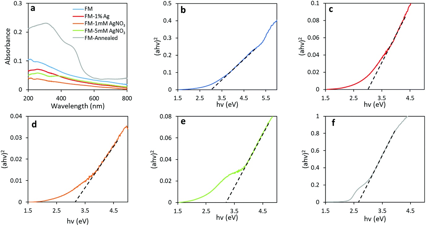 | ||
| Fig. 9 (a) UV-Vis spectra of all samples and Tauc plots for samples of: (b) FM, (c) FM-1% Ag, (d) FM-1 mM AgNO3, (e) FM-5 mM AgNO3 and (f) FM-annealed. | ||
Mott–Schottky measurements were undertaken to determine the flat potential, Vfb for each sample. The conduction band minimum, CBmin can be derived from the relation CBmin = EAg/AgCl − Vfb, in which EAg/AgCl is the absolute electrode potential with respect to the reference system (Fig. S2†).
The data evolved in these analyses: XPS valence band, Tauc analysis from UV-Vis spectra and Mott–Schottky measurements allowed an assessment of the electronic band structure of the prepared samples to be determined which is presented in Fig. 10 and Table 1. It can be seen from the band diagram of different samples that the incorporation of does not change Ag the conduction band significantly. However, their valence band are influenced by the Ag species as well as the annealing process. For instance, the valence band of the samples prepared with AgNO3 drops, which favours generating OH radicals (2.72 V)66 and therefore those samples may exhibit higher activity if the dyes are degraded through this mechanism.
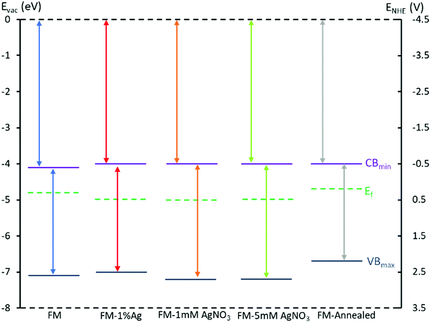 | ||
| Fig. 10 Band diagram using conduction band from Mott Schottky, optical bandgap from Tauc plots and valence band value from XPS valence spectra for all studied samples: FM, FM-1% Ag, FM-1 mM AgNO3, FM-5 mM AgNO3 and FM-annealed. | ||
| Samples | UV-Visible (eV) | Mott–Schottky (eV) | XPS valence (eV) |
|---|---|---|---|
| FM | 3.00 | −4.06 | −7.06 |
| FM-1% Ag | 3.00 | −3.98 | −6.98 |
| FM-1 mM AgNO3 | 3.15 | −4.04 | −7.19 |
| FM-5 mM AgNO3 | 3.20 | −4.02 | −7.22 |
| FM-annealed | 2.65 | −4.02 | −6.67 |
Photocatalytic activity
The photocatalytic activity of the synthesised FM-based samples was evaluated through the degradation of organic dyes. Two types of azo dyes, Congo red and methylene blue, are tested and compared. In Fig. 11a, the decreasing trend of absorbance curves measured during a typical test is presented. The results of repeated tests are also shown in the inset figure which shows the reproducibility of the tests. Furthermore, controlled tests for only Ag particles (<150 nm, 99%, Sigma-Aldrich) is conducted (Fig. S5†), but, the Ag particles do not show superior dye degradation activity towards both Congo red and methylene blue dyes, which is in consistent with the reported works.67,68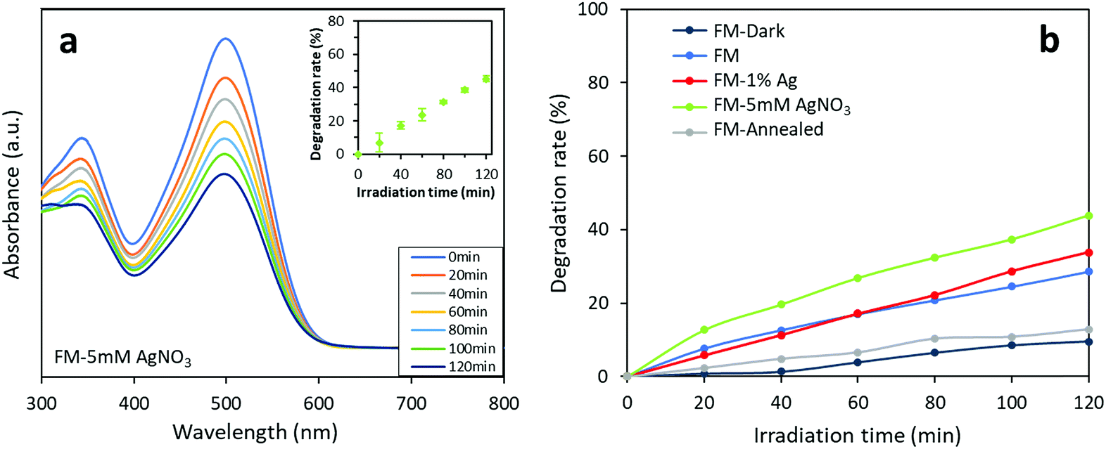 | ||
| Fig. 11 Photocatalytic activity of the FM-based samples towards Congo red: (a) absorbance curves of the FM-5 mM AgNO3 sample. The inset shows the results of three repeated tests on the same sample which indicates the reproducibility of the experiment. (b) Comparison of photocatalytic activity of different of the FM-based photocatalysts. The experimental data is presented in Table S1.† | ||
As shown in Fig. 11b, the photocatalysts prepared using various methods demonstrate different degradation activities against Congo red. A controlled test without irradiation validifies that the measured dye degradation comes from a photocatalytic process enabled by the particles. It can also be found that while the degradation rate for the sample prepared with bare FM only reaches 29% after 120 min, the degradation rate is improved for the Ag-modified samples, due to the presence of silver. The sample prepared by adding AgNO3 solution during sonication and adding Ag powder before sonication show a 2 hour degradation rate of 44% and 34%, respectively. The results indicate that the modification of the FM particles with Ag species in general improves the photocatalytic degradation activity of the samples towards Congo red. Moreover, the different photocatalytic activities between the two Ag-modified samples show that the method of introducing Ag in its ionic form during the ultrasonication process is more effective than dispersing elemental Ag in the FM prior to the ultrasonication process. This coincides with the XRD, XPS and Raman characterisations that the former results in a higher concentration of surface Ag species compared with the latter. Consequently, the increase of Ag content in the core of the particles and the formation of Ag containing clusters can be assigned to this enhancement. However, the annealed FM particle sample is not found to exhibit higher activity. Presumably, this is because the particles before annealing already possess a partially oxidised surface forming heterostructures for separating the generated electron–holes photocatalytically.
Interestingly, when switching from Congo red to methylene blue, the FM-based photocatalysts shows a totally different photocatalytic behaviour (Fig. 12). All the samples are found to exhibit very similar 2 hour degradation rates of about 60% towards methylene blue. However, the sample prepared with bare FM, which demonstrates the lowest Congo red degradation rate, shows a slightly higher degradation rate (65%) towards methylene blue than the other samples. The results indicate that the FM-based photocatalysts degrade the two dyes through different photocatalytic mechanisms. Recalling the results for the Congo red group, the tailorable activity of the FM-based photocatalysts towards a specified dye can be realised.
We propose that the competing photocatalytic degradation process between the parent FM and the introduced Ag is responsible for the different expression of the Ag modification towards the two different types of dyes. Since in comparison to the oxides of FM particles, Ag shows a higher photocatalytic degradation activity towards Congo red,69,70 modifying the FM particles with Ag improves the catalytic activity of Ag which is traditionally known to impact the functional groups in Congo red.71,72 When it comes to methylene blue, the oxides of the parent FM already have very high activity towards this specific dye while Ag is not specific toward methylene blue.67,73,74 Here for methylene blue, what seems to be the most critical aspect is the formation of defects, which are formed within and on the surface of the particles, during the solidification of the liquid metal.
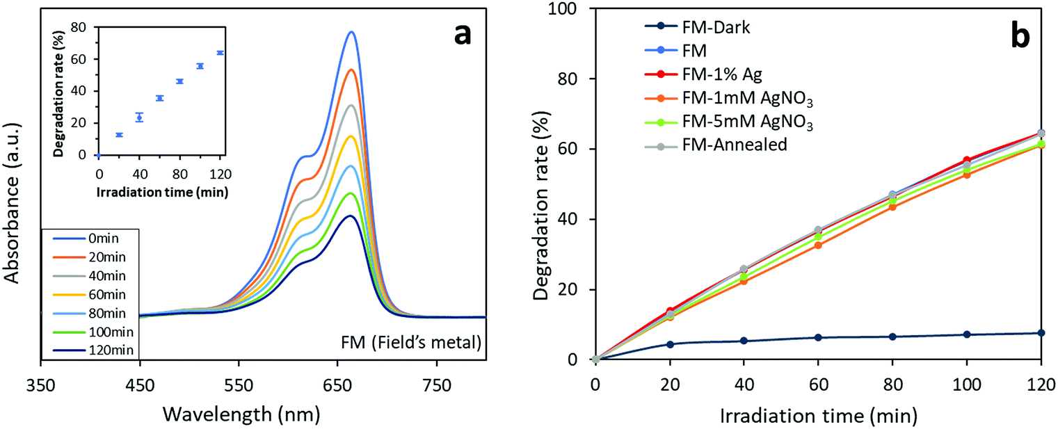 | ||
| Fig. 12 Photocatalytic activity of the FM-based photocatalysts towards methylene blue: (a) absorbance curves of the FM sample. The inset shows the results of repeated tests on the three FM samples to demonstrate reproducibility of the tests. (b) Comparison of photocatalytic activity of different of the FM-based photocatalysts. The experimental data is presented in Table S2.† | ||
Conclusions
We have successfully demonstrated the synthesis of micro- and sub-micro particles of Field's metal via an ultrasonication approach at a low processing temperature. We showed how modification to the particles influences their photocatalytic activity towards different types of dyes. Ag incorporation to the Field's metal system improves the catalytic performance towards Congo red whereas the parent Field's metal particles (without Ag incorporation) exhibit higher photocatalytic activity towards methylene blue. We revealed the fundamental phase separation and selective surface oxidation accompanied with the liquid metal ultrasonication and solidification process, as well as the selective distribution of a foreign metal when introduced to the Field's metal system. Our one-step method is able to produce heterostructure core–shell particles of a Schottky nature where the solidification process introduces specific defects. We also showed that modifying the sample with other metal species can selectively improve the activity of the photocatalyst towards specific dyes. Altogether, our work demonstrated an easily scalable route for producing photocatalysts based on low-melting-point liquid metals. Also, our findings are expected to have insightful implications for the future development of high performance photocatalysts with extended dye selectivity.Conflicts of interest
There are no conflicts to declare.Author contributions
S. A. I.-S., J. T. and K. K.-Z. introduced the concept and designed the experiments. S. A. I.-S performed all the experiments which included synthesising the materials and photocatalysis and also carried out the characterisations with the help of others. J. T. and M. B. G. assisted with the XRD characterisations and TEM analysis. J. Y. contributed in the UV-Vis measurements. J. H. performed the Mott–Schottky measurements and helped to analyse it. N. S and T. D. conducted and analysed the XPS measurements of the available samples. R. A. helped to perform the DSC analysis. P. K. participated in the thermodynamic calculation and its analysis. S. A. I.-S, J. T., M. B. G., K. K.-Z. and A. P. O. contributed in the analysis of data, scientific discussions and authorship of the manuscript. All authors participated in writing and revising the manuscript and giving comments.Acknowledgements
The authors gratefully acknowledge the Australian Research Council (ARC) Laureate Fellowship grant (FL180100053) and ARC Centre of Excellence FLEET (CE170100039) for the financial support in this work.References
- K. Ma and J. Liu, Front. Energ. Power Eng. China, 2007, 1, 384 CrossRef.
- A. Miner and U. Ghoshal, Appl. Phys. Lett., 2004, 85, 506 CrossRef CAS.
- Y. Zheng, Z. He, Y. Gao and J. Liu, Sci. Rep., 2013, 3, 1786 CrossRef.
- M. D. Dickey, R. C. Chiechi, R. J. Larsen, E. A. Weiss, D. A. Weitz and G. M. Whitesides, Adv. Funct. Mater., 2008, 18, 1097 CrossRef CAS.
- T. Liu, P. Sen and C. Kim, J. Microelectromech. Syst., 2012, 21, 443 CAS.
- S.-Y. Tang, Y. Lin, I. D. Joshipura, K. Khoshmanesh and M. D. Dickey, Lab Chip, 2015, 15, 3905 RSC.
- M. D. Dickey, ACS Appl. Mater. Interfaces, 2014, 6, 18369 CrossRef CAS.
- S. Wenjiang, R. T. Edwards and K. Chang-Jin, J. Microelectromech. Syst., 2006, 15, 879 CrossRef.
- P. A. Giguère and D. Lamontagne, Science, 1954, 120, 390 CrossRef.
- M. D. Bartlett, N. Kazem, M. J. Powell-Palm, X. Huang, W. Sun, J. A. Malen and C. Majidi, Proc. Natl. Acad. Sci. U. S. A., 2017, 114, 2143 CrossRef CAS.
- A. Fassler and C. Majidi, Adv. Mater., 2015, 27, 1928 CrossRef CAS.
- Y. Deng and J. Liu, Heat Mass Tansfer, 2010, 46, 1327 CrossRef CAS.
- L. Ren, J. Zhuang, G. Casillas, H. Feng, Y. Liu, X. Xu, Y. Liu, J. Chen, Y. Du, L. Jiang and S. X. Dou, Adv. Funct. Mater., 2016, 26, 8111 CrossRef CAS.
- L. Yi and J. Liu, Int. Mater. Rev., 2017, 62, 415 CrossRef CAS.
- R. C. Gough, J. H. Dang, A. M. Morishita, A. T. Ohta and W. A. Shiroma, Presented in part at the 2014 Asia-Pacific Microwave Conference, Sendai, Japan, 2014 Search PubMed.
- N. Taccardi, M. Grabau, J. Debuschewitz, M. Distaso, M. Brandl, R. Hock, F. Maier, C. Papp, J. Erhard, C. Neiss, W. Peukert, A. Görling, H. P. Steinrück and P. Wasserscheid, Nat. Chem., 2017, 9, 862 CrossRef CAS.
- W. Xu, N. Birbilis, G. Sha, Y. Wang, J. E. Daniels, Y. Xiao and M. Ferry, Nat. Mater., 2015, 14, 1229 CrossRef CAS.
- L. Wang and J. Liu, Sci. China Technol. Sci., 2014, 57, 1721 CrossRef CAS.
- D. Pan, L. Zhang, J. Zhuang, W. Lu, R. Zhu and W. Qin, Mater. Lett., 2012, 68, 472 CrossRef CAS.
- Z. Lv, X. Liu, B. Jia, H. Wang, Y. Wu and Z. Lu, Sci. Rep., 2016, 6, 34213 CrossRef CAS.
- W. Zhang, B. S. Naidu, J. Z. Ou, A. P. O'Mullane, A. F. Chrimes, B. J. Carey, Y. Wang, S.-Y. Tang, V. Sivan, A. Mitchell, S. K. Bhargava and K. Kalantar-zadeh, ACS Appl. Mater. Interfaces, 2015, 7, 1943 CrossRef CAS.
- W. Zhang, J. Z. Ou, S.-Y. Tang, V. Sivan, D. D. Yao, K. Latham, K. Khoshmanesh, A. Mitchell, A. P. O'Mullane and K. Kalantar-zadeh, Adv. Funct. Mater., 2014, 24, 3799 CrossRef CAS.
- J. N. Butler and M. L. Meehan, Trans. Faraday Soc., 1966, 62, 3524 RSC.
- G. Ding, Y. Zhu, S. Wang, Q. Gong, L. Sun, T. Wu, X. Xie and M. Jiang, Carbon, 2013, 53, 321 CrossRef CAS.
- D. A. Torelli, S. A. Francis, J. C. Crompton, A. Javier, J. R. Thompson, B. S. Brunschwig, M. P. Soriaga and N. S. Lewis, ACS Catal., 2016, 6, 2100 CrossRef CAS.
- A. Zavabeti, J. Z. Ou, B. J. Carey, N. Syed, R. Orrell-Trigg, E. L. H. Mayes, C. Xu, O. Kavehei, A. P. O'Mullane, R. B. Kaner, K. Kalantar-Zadeh and T. Daeneke, Science, 2017, 358, 332 CrossRef CAS.
- M. Shafiei, F. Hoshyargar, N. Motta and A. P. O'Mullane, Mater. Des., 2017, 122, 288 CrossRef CAS.
- M. Kang, J. Wang, H. Gao, Y. Han, G. Wang and S. He, Materials, 2017, 10, 250 CrossRef.
- S.-Y. Tang, D. R. G. Mitchell, Q. Zhao, D. Yuan, G. Yun, Y. Zhang, R. Qiao, Y. Lin, M. D. Dickey and W. Li, Matter, 2019, 1, 192 CrossRef.
- Z. Wang, W. Qiu, Y. Yang and C. T. Liu, Intermetallics, 2015, 64, 63 CrossRef CAS.
- F. Yan, Y. Wang, J. Zhang, Z. Lin, J. Zheng and F. Huang, ChemSusChem, 2014, 7, 101 CrossRef CAS PubMed.
- X.-h. Li and M. Antonietti, Chem. Soc. Rev., 2013, 42, 6593 RSC.
- T. Daeneke, K. Khoshmanesh, N. Mahmood, I. A. De Castro, D. Esrafilzadeh, S. J. Barrow, M. D. Dickey and K. Kalantar-Zadeh, Chem. Soc. Rev., 2018, 47, 4073 RSC.
- F. Hoshyargar, J. Crawford and A. P. O'Mullane, J. Am. Chem. Soc., 2017, 139, 1464 CrossRef CAS.
- H. Cao, S. Huang, Y. Yu, Y. Yan, Y. Lv and Y. Cao, J. Colloid Interface Sci., 2017, 486, 176 CrossRef CAS PubMed.
- G. Xi and J. Ye, Chem. Commun., 2010, 46, 1893 RSC.
- X. Zhang, D. Huang, K. Xu, D. Xu, F. Liu and S. Zhang, Semiconductor Photocatalysis-Materials, Mechanisms and Applications, IntechOpen, 2016 Search PubMed.
- X. C. Meng and Z. Zhang, J. Mol. Catal. A-Chem., 2016, 423, 533 CrossRef CAS.
- Y. Lu, Q. Hu, Y. Lin, D. Pacardo, C. Wang, W. Sun, F. Ligler, M. Dickey and Z. Gu, Nat. Commun., 2015, 6, 10066 CrossRef CAS.
- Y. Lin, Y. Liu, J. Genzer and M. D. Dickey, Chem. Sci., 2017, 8, 3832 RSC.
- N. Syed, A. Zavabeti, M. Mohiuddin, B. Zhang, Y. Wang, R. S. Datta, P. Atkin, B. J. Carey, C. Tan, J. Van Embden, A. S. R. Chesman, J. Z. Ou, T. Daeneke and K. Kalantar-Zadeh, Adv. Funct. Mater., 2017, 27, 1702295 CrossRef.
- X.-Y. Dong, Z.-W. Gao, K.-F. Yang, W.-Q. Zhang and L.-W. Xu, Catal. Sci. Technol., 2015, 5, 2554 RSC.
- C. W. Bale, E. Bélisle, P. Chartrand, S. A. Decterov, G. Eriksson, A. E. Gheribi, K. Hack, I. H. Jung, Y. B. Kang, J. Melançon, A. D. Pelton, S. Petersen, C. Robelin, J. Sangster, P. Spencer and M. A. Van Ende, Calphad, 2016, 54, 35 CrossRef CAS.
- J. W. Yeh, S. K. Chen, S. J. Lin, J. Y. Gan, T. S. Chin, T. T. Shun, C. H. Tsau and S. Y. Chang, Adv. Eng. Mater., 2004, 6, 299 CrossRef CAS.
- W. L. Wang, Y. H. Wu, L. H. Li, W. Zhai, X. M. Zhang and B. Wei, Sci. Rep., 2015, 5, 16335 CrossRef CAS.
- L. Bo, S. Li, L. Wang, D. Wu, M. Zuo and D. Zhao, Results Phys., 2018, 8, 1086 CrossRef.
- S. Raoux, A. K. König, H.-Y. Cheng, D. Garbin, R. W. Cheek, J. L. Jordan-Sweet and M. Wuttig, Phys. Status Solidi, 2012, 249, 1999 CrossRef CAS.
- J. Zhang, Z. Ma, W. Jiang, Y. Zou, Y. Wang and C. Lu, J. Electroanal. Chem., 2016, 767, 49 CrossRef CAS.
- J. Zhu, S. Wang, J. Wang, D. Zhang and H. Li, Appl. Catal. B-Environ., 2011, 102, 120 CrossRef CAS.
- J. F. Moulder and J. Chastain, Handbook of X-ray Photoelectron Spectroscopy: A Reference Book of Standard Spectra for Identification and Interpretation of XPS Data, Physical Electronics Division, Perkin-Elmer Corporation, 1992 Search PubMed.
- M. M. Rahman, M. M. Alam, M. M. Hussain, A. M. Asiri and M. E. M. Zayed, Environ. Nanotechnol. Monit. Manage., 2018, 10, 1 CAS.
- J. Shen, J. Xue, G. He, J. Ni, Z. Chen, B. Tang, Z. Zhou and H. Chen, J. Mater. Sci., 2018, 53, 12040 CrossRef CAS.
- J.-c. Dupin, D. Gonbeau, P. Vinatier and A. Levasseur, Phys. Chem. Chem. Phys., 2000, 2, 1319 RSC.
- H. Baker, ASM handbook: Alloy phase diagrams, ASM International, 1992, Vol. 3 Search PubMed.
- V. Kochat, A. Samanta, Y. Zhang, S. Bhowmick, P. Manimunda, S. A. S. Asif, A. S. Stender, R. Vajtai, A. K. Singh, C. S. Tiwary and P. M. Ajayan, Sci. Adv., 2018, 4, e1701373 CrossRef.
- G. Bo, L. Ren, X. Xu, Y. Du and S. Dou, Adv. Phys: X, 2018, 3, 411 CAS.
- M. D. Dickey, R. C. Chiechi, R. J. Larsen, E. A. Weiss, D. A. Weitz and G. M. Whitesides, Adv. Funct. Mater., 2008, 18, 1097 CrossRef CAS.
- G. Ming, Z. Wu, T. Mon-Che, Z. Jigang, G. Mingyun, L. Meng-Chang, Z. Bo, H. Yongfeng, W. Di-Yan, Y. Jiang, J. P. Stephen, H. Bing-Joe and D. Hongjie, Nat. Commun., 2014, 5, 4695 CrossRef.
- L. Xin-Hao, B. Moritz, B. Siegfried and A. Markus, Sci. Rep., 2013, 3, 1743 CrossRef.
- J. Yang, R. Frost and W. Martens, J. Therm. Anal. Calorim., 2010, 100, 109 CrossRef CAS.
- K. Yadav, B. R. Mehta and J. P. Singh, J. Mater. Chem. C, 2014, 2, 6362 RSC.
- G. I. N. Waterhouse, G. A. Bowmaker and J. B. Metson, Phys. Chem. Chem. Phys., 2001, 3, 3838 RSC.
- G. J. Millar, J. B. Metson, G. A. Bowmaker and R. P. Cooney, J. Chem. Soc. Faraday Trans., 1995, 91, 4149 RSC.
- H. A. Pray, C. E. Schweickert and B. H. Minnich, Ind. Eng. Chem., 1952, 44, 1146 CrossRef CAS.
- A. Sadeghzadeh-Attar and M. R. Bafandeh, CrystEngComm, 2018, 20, 460 RSC.
- J. Ma, F. Wang and M. Mostafavi, Molecules, 2018, 23, 244 CrossRef PubMed.
- R. M. Kumari, N. Thapa, N. Gupta, A. Kumar and S. Nimesh, Adv. Nat. Sci.: Nanosci. Nanotechnol., 2016, 7, 045009 Search PubMed.
- Q. Deng, X. Duan, D. H. L. Ng, H. Tang, Y. Yang, M. Kong, Z. Wu, W. Cai and G. Wang, ACS Appl. Mater. Interfaces, 2012, 4, 6030 CrossRef CAS PubMed.
- H. Kolya, P. Maiti, A. Pandey and T. Tripathy, J. Anal. Sci. Technol., 2015, 6, 1 CrossRef.
- T. N. J. I. Edison, R. Atchudan, M. G. Sethuraman and Y. R. Lee, J. Photochem. Photobiol., B, 2016, 162, 604 CrossRef CAS.
- M. Ghaedi, M. N. Biyareh, S. N. Kokhdan, S. Shamsaldini, R. Sahraei, A. Daneshfar and S. Shahriyar, Mater. Sci. Eng. C, 2012, 32, 725 CrossRef CAS.
- R. Rajesh, S. S. Kumar and R. Venkatesan, New J. Chem., 2014, 38, 1551 RSC.
- K. Roy, C. Sarkar and C. Ghosh, Appl. Nanosci., 2015, 5, 953 CrossRef CAS.
- M. Suresh and A. Sivasamy, J. Environ. Chem. Eng., 2018, 6, 3745 CrossRef CAS.
Footnote |
| † Electronic supplementary information (ESI) available. See DOI: 10.1039/c9ta05200c |
| This journal is © The Royal Society of Chemistry 2019 |