 Open Access Article
Creative Commons Attribution 3.0 Unported Licence
Glyme-based liquid–solid electrolytes for lithium metal batteries†
M.
Nojabaee
 ,
J.
Popovic
 * and
J.
Maier
Max Planck Institute for Solid State Research, Stuttgart, Germany. E-mail: popovic@fkf.mpg.de
First published on 9th May 2019
Abstract
The development of stable electrolytes for lithium metal batteries is urgently required. In this work, nanoporous alumina/lithium salt-containing glyme liquid–solid composite electrolytes are proposed. The beneficial interfacial effect and transport properties such as ionic conductivity and lithium transference number can be tuned by variation of the cell temperature and electrolyte salt concentration. In symmetrical lithium/electrolyte/lithium cells, glyme-based liquid–solid electrolytes show superior performance compared to their liquid counterparts. However, even in the high lithium transference number cases, unfavorable mossy lithium deposits can be observed.
1. Introduction
Ever since the discovery of the lithium ion batteries, lithium metal has been envisaged as an optimal anode due to the highest theoretical capacity (3860 mA h g−1) and the lowest electrochemical potential (−3.04 V vs. hydrogen electrode).1–5 On the other hand, lithium metal is particularly interesting for the development of the so-called next generation Li–S and Li–O2 battery technologies.6,7 Key challenges in lithium metal batteries are poor safety and cycleability, a consequence of the instable solid electrolyte interphase (SEI) forming between the typical electrolytes and the lithium anode, as well as deposition of lithium in mossy or dendritic form.8,9 Recently, a number of solutions have been proposed, including chemical or physical pre-treatment of the lithium metal to form an artificial SEI,10–14 homogenization of the Li-ion flux,15–17 tuning of the shear modulus of the electrolyte and application of external pressure,18–22 as well as electrolyte composition adaptation.23–27An interesting class of materials, suggested to be useful in lithium metal batteries, are liquid/solid (hybrid) electrolytes, created by infiltration of salt-in-solvent electrolytes into nanoporous solid matrix.28–31 Appropriate liquid/solid electrolytes offer high ionic conductivities accompanied with good adhesion properties, and high shear modulus. Solids which offer beneficial surface adsorption properties are able to immobilize the anions on the surface, locally enhance the Li+ conductivity and boost the lithium transference number without compromising overall conductivity.32–34 Such liquid/solid electrolytes have the potential to enable dendrite-free lithium metal batteries at lower currents.35,36
In this work, we report on anodic aluminium oxide (AAO) membranes infiltrated with glyme-based lithium electrolytes as potential candidates for lithium metal batteries. AAO membranes are chosen as they offer well-defined porosities with small enough pore size, while glyme-based electrolytes already showed good stability vs. lithium electrode.34,37 We investigate systematically how the changes in temperature and salt concentration influence interfacial effects and transport properties such as ionic conductivity and lithium transference number. Finally, we investigate the failure mechanism of the Li|liquid/solid electrolyte|Li cells as well as the structure of the lithium deposits formed during lithium/stripping plating experiments.
2. Experimental
Characterization of the anodic aluminum oxide (AAO)
The morphology of the AAO monoliths (diameter, d = 13 mm, thickness t = 60 μm, Whatman Anodisc® purchased from Sigma-Aldrich) was observed using scanning electron microscopy (SEM, Zeiss Merlin device operating at 5 kV). The samples were coated with a conducting carbon layer prior to the SEM measurement. The X-ray diffraction pattern was obtained in ambient environment using a Philips device with Cu Kα 1 (λ = 0.154 nm) radiation. Magic angle spinning (MAS) NMR measurements were performed on a Bruker Avance III 400 MHz instrument in a magnetic field of 9.4 T, with a Larmor frequency of 400.1 Hz for 1H at room temperature and a spinning speed of 12![[thin space (1/6-em)]](https://www.rsc.org/images/entities/char_2009.gif) 500 Hz. A N2 adsorption–desorption apparatus (BELSORP-mini II, Bel Japan Inc.) was employed to characterize the porosity of the AAO membranes. Prior to the measurement, samples were degassed overnight at 120 °C under vacuum. Brunauer–Emmet–Teller method was used to calculate the surface area from the N2 desorption curve. The ion exchange capacity (IEC) of the –OH groups in AAO was calculated from the potentiometric titrations. For that purpose, a defined amount of crushed AAO particles was dispersed in a 0.1 M NaCl aqueous solution, stirred continuously for 1 h, and subsequently titrated by a 0.01 M NaOH solution, followed by back-titration with a 0.01 HCl solution up to the neutral pH values.
500 Hz. A N2 adsorption–desorption apparatus (BELSORP-mini II, Bel Japan Inc.) was employed to characterize the porosity of the AAO membranes. Prior to the measurement, samples were degassed overnight at 120 °C under vacuum. Brunauer–Emmet–Teller method was used to calculate the surface area from the N2 desorption curve. The ion exchange capacity (IEC) of the –OH groups in AAO was calculated from the potentiometric titrations. For that purpose, a defined amount of crushed AAO particles was dispersed in a 0.1 M NaCl aqueous solution, stirred continuously for 1 h, and subsequently titrated by a 0.01 M NaOH solution, followed by back-titration with a 0.01 HCl solution up to the neutral pH values.
Electrolyte preparation
The composite electrolytes were prepared by infiltration of dry nanoporous AAO with a solution of 0.02–1 M lithium trifluoromethanesulfonate (LiCF3SO3, Sigma-Aldrich, 99.995%, LiTf) in tri(ethylene glycol)dimethyl ether (Mw = 178.2 g mol−1, Sigma-Aldrich, triglyme) overnight. Triglyme solvent was distilled prior to use, and the water content of the final electrolyte thus kept below 150 ppm.Electrolyte characterization
For the electrochemical measurements, the electrolytes were sandwiched between two symmetric lithium electrodes in a self-designed copper-plated polytetrafluorethylen (PTFE) cell. Impedance spectroscopy was applied before and after galvanostatic polarization in the frequency range from 10−1 to 107 Hz (0.1 V amplitude) using a Solartron 1260 frequency analyzer. When needed, the temperature was externally controlled by a RC6CP Lauda thermostat. The ionic conductivities were calculated from the cell geometry and the obtained resistances. The lithium plating/stripping experiments and the galvanostatic polarization measurements were performed with a Keithley 2604B source-meter instrument. Thermal properties of the electrolytes were determined using a differential scanning calorimeter (DSC 214, Polyma, Netzsch) in the temperature range from −100 °C to 80 °C at a heating rate of 10 °C min−1 under continuous nitrogen purging rate of 60 mL min−1. Zeta potential was measured at room temperature in a closed vessel, by measuring the magnitude and phase of the Colloid Vibration Current (CVI) at 3 MHz, using an electroacoustic spectrometer (DT-1200, Dispersion Technology, Inc., Quantachrome). Electrolyte preparation and the electrochemical measurements (excluding the temperature dependent measurements and zeta potential measurements) were performed in a glovebox (<0.1 ppm H2O, ≤0.1 ppm O2) under Ar atmosphere.Lithium dendrite characterization
Upon disassembling the cell in the Ar-filled glovebox, visible brown discolorations (dendrites) inside and on the top of AAO were collected and either deposited on scanning electron microscopy (SEM) sample holders or crushed, dispersed in ethanol and subsequently deposited on carbon grids for transmission electron microscopy (TEM) measurements. TEM measurements were performed using a Philips, CM200 instrument at low energies.3. Results and discussion
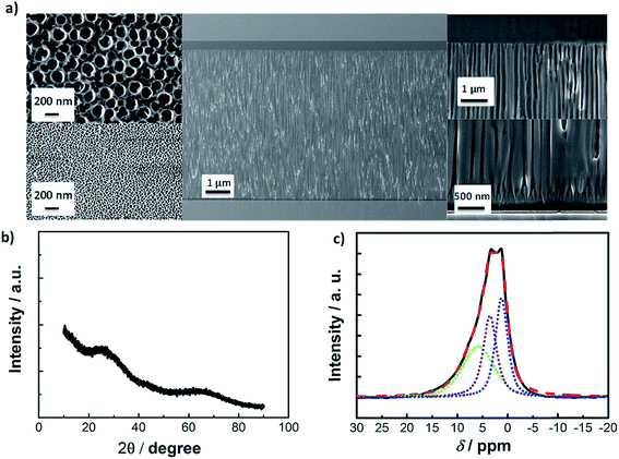
In the present study, AAO membranes with high pore density, controlled pore size, shape and orientation as illustrated in the SEM image in Fig. 1a, have been employed as the solid part of the liquid–solid electrolyte. The pores of the AAO membrane have conical frustum form with an average upper base radius of 20 nm and a 200 nm lower base radius, Fig. 1a, left. Using the given geometry and the approximate number of pores observed in the SEM micrographs, a surface area value of Acalc = 35 m2 g−1 can be estimated (available in the ESI†). Additionally, the Brunauer–Emmet–Teller (BET) surface area is measured to be of a similar order of magnitude, SBET = 24 m2 g−1. X-ray diffraction patterns of the AAO membrane asserts the amorphous nature of the Al2O3 material, Fig. 1b.In 1H magic-angle spinning nuclear magnetic resonance (MAS-NMR) spectra of the crushed AAO samples, a broad chemical shift is observed around 5 ppm, Fig. 1c. This shift can be fitted by three Gaussian components corresponding to the protons in physically adsorbed water (δ = 5.9 ppm, green dotted line) and to the –OH groups bound to aluminum (δ = 3.5 ppm and δ = 1.3 ppm, purple and blue dotted line), giving a total number of 2.4 × 10²⁰ –OH per g−1. The total density of the –OH groups is calculated to be 6 nm−2, taking into account the total number of –OH groups from 1H MAS-NMR and the calculated surface area, Acalc. The predominant adsorption of Tf− anion on the AAO surface in contact with 1 M LiTf/triglyme is expected to lead to an interfacial (or “soggy sand”) effect.33 Indeed, the effective surface zeta potential (ζeff) of crushed 1 vol% AAO particles dispersed in 1 M LiTf/triglyme electrolyte is negative, ζeff = −28 mV (ζeff = −6 mV in 0.2 LiTf/triglyme). However, when the activity of the –OH groups (surface deprotonation) of crushed AAO membranes was probed by potentiometric titrations, values of IEC = 7.2 × 10⁻² mmol g−1 are measured, an order of magnitude lower than what has been observed for porous SiO2 particles in a similar solvent.38 With this in mind, the interfacial effect in AAO: glyme electrolytes is expected to be milder than in the SiO2: glyme-based lithium electrolytes. The AAO: (1 M LiTf/triglyme) electrolyte appears transparent (Fig. S1†) despite its relatively high volume fraction of Al2O3 solid, φ = 0.24, and has thermal properties which are comparable to the pure 1 M LiTf/triglyme.
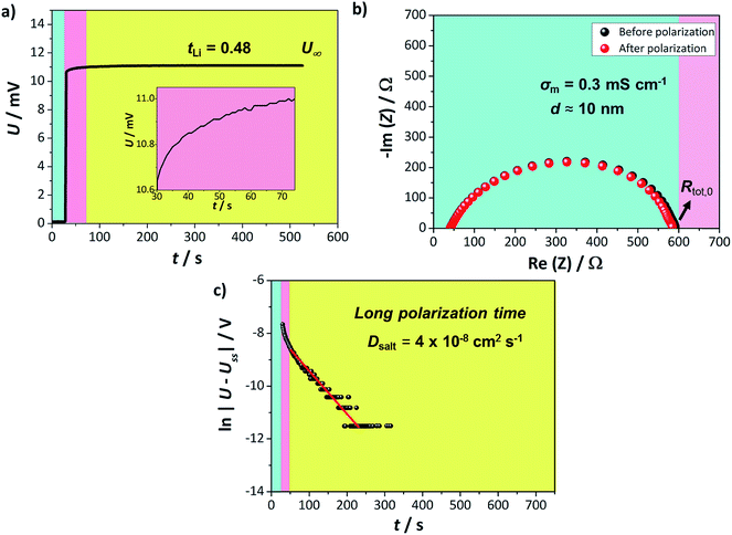
The lithium transference number of AAO: (LiTf/triglyme) was measured using the galvanostatic polarization method as reported previously.34 In such a measurement, the salt concentration gradient establishes eventually upon applying constant current and at the steady state, the voltage response results solely from the cation (lithium) transport. The contributions of other resistances to the overall voltage increase, such as the resistances of the passivation layers (solid electrolyte interphase, SEI) formed on the lithium electrodes, should also be considered. The lithium transference number can subsequently be calculated from:
 | (1) |
The semicircle observed in Fig. 2b corresponds to the SEI formed on the lithium metal surface in contact with the liquid part of the electrolyte. Such SEI appears to be stable during the polarization process with approximate thickness around 10 nm, when calculated for the approximate dielectric constant ε ≈ 10 (calculation available in ESI†). Thus, even though the tLi values reported are of the same order as previously seen for liquid lithium electrolytes, the composite appears more promising due to its stability vs. lithium. Furthermore, the U(t) curve exhibits a clear exponential behavior for longer times, enabling us to determine the LiTf salt diffusion coefficient from
 | (2) |
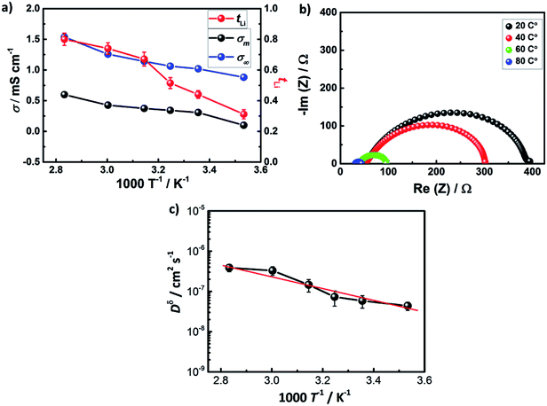
Fig. 3a shows ionic conductivity and lithium transference number in AAO: (1 M LiTf/triglyme) electrolyte in the temperature range from 10 to 80 °C, where the conductivity of the composite liquid/solid electrolyte improves from 1.8 to 2.6 mS cm−1. The ratio of the ionic conductivity of the liquid/solid composite and the bulk liquid electrolyte stays constant in the entire temperature range (σm/σ∞ ≈ 0.5), indicating similar conduction mechanisms and partial blocking of some pathways in the liquid/solid composite electrolyte. Indeed, it is even visible from the SEM that not all of the pores in AAO are continuous and interconnected. A more drastic effect has been observed for the lithium transference number of the liquid/solid composite, leading to the highest value of tLi = 0.80 at 80 °C. This can be explained either by activation of additional surface –OH groups of AAO and/or through changes in the molecular speciation in the liquid electrolyte upon heating, investigated using temperature controlled IR spectroscopy (Fig. S2†). Indeed, temperature increase enhances the ion-pair association to ion pairs and dimers in 1 M LiTf/triglyme (similarly as in LiTf/diglyme38,39). The strong solvation of free ions (about 3 glyme molecules) causes endothermic association reaction and entropy gain through association. The result is a stronger interfacial effect and high tLi in AAO: (1 M LiTf/triglyme). At higher temperatures, the increase in ionic conductivity accompanied with the depression in concentration of free ions implies a total mobility increase about 4 times. This is in line with the observed viscosity increase in liquid 1 M LiTf/triglyme (Fig. S3†).
With increasing temperature, a substantial depletion of the resistance of the SEI layer, RSEI, is observed, Fig. 3b, suggesting its chemical composition or morphological changes. This specific point will be discussed in the subsequent work. Following the mobility trend, salt diffusion coefficient, Dδ, increases an order of magnitude in the chosen temperature range (Fig. 3c).
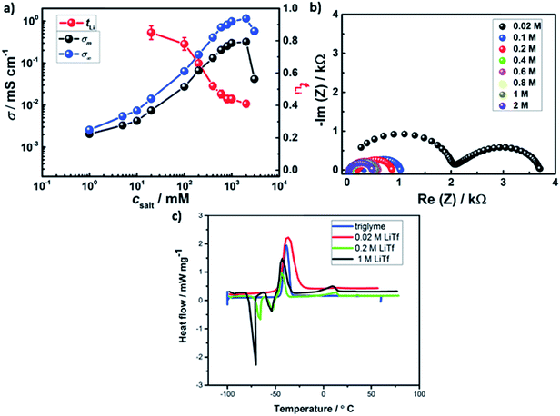
Fig. 4a shows the effect of salt concentration on room temperature ionic conductivity and lithium transference number in AAO: LiTf/triglyme. A sharp rise (about 2 orders of magnitude) in the ionic conductivity of liquid/solid composite electrolyte upon increasing concentration from 0.02 M to 0.4 M is observed, followed by a plateau and a drop at high salt concentrations.
To discuss the interfacial effect in the present system, two extreme cases of strong and weak anion adsorption can be considered. In the case of weak anion adsorption, space charge effects are negligible and – if all pathways percolating – the conductivity of the composite is simply given by
| σm = (1 − φ)σ∞, | (3) |
In the case of strong anion adsorption on AAO, for sufficiently high surface area, we can assume that all the anions are adsorbed, including the ones in the ion pairs. The cations are then all in the space charge zones. As we can neglect bulk contribution, the conductivity of the composite can be written as
| σm = (1 − φ)csaltu+, | (4) |
| σ∞ = c+(u+ + u−) | (5) |
The values of c+ can be taken from the previous measurements of the triflate stretching band by infrared spectroscopy, while the mobilities can be taken from the deconvoluted contributions of specific ions to the overall conductivity (σ+, σ−) leading to values of σm/σ∞ ≈ 0.15 at 1 M LiTf and σm/σ∞ ≈ 0.5 at 0.2 M LiTf.38 In the case of strong adsorption, transference number of 1 is expected.
As the conductivity and lithium transference number are in between the cases of weak and strong adsorption, medium level of adsorption appears to be relevant. A more precise approach would require more information than available. The ratio of the ionic conductivity of the bulk and the ionic conductivity of the liquid/solid composite varies from of σm/σ∞ = 0.8 for 0.02 M LiTf to σm/σ∞ = 0.3 at 1 M LiTf, suggesting stronger adsorption at low csalt and milder adsorption at high csalt. Following the weakening of the adsorption trend, the lithium transference number significantly decreases upon salt addition from tLi = 0.85 at 0.02 M to tLi = 0.52 at 0.4 M, and the trend continues with somewhat lower rate at higher salt concentrations.
At lower salt concentrations, an additional semicircle corresponding to the electrolyte bulk appears (Fig. 4b). On the other hand, the SEI thickness rises to d ≈ 40 nm. Interestingly, the DSC spectra of AAO: 0.02 M LiTf/triglyme is drastically different to other liquid–solid electrolytes with salt concentration between 0.2–1 M (Fig. 4c) and is almost identical to the DSC of pure triglyme.
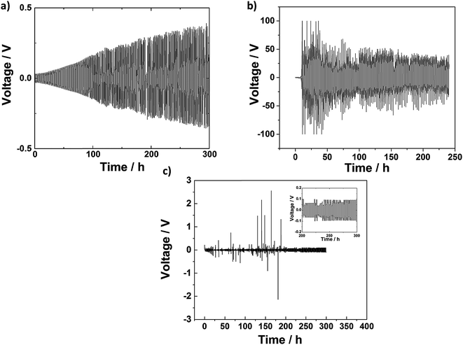
To further investigate the cyclability of this class of electrolytes in the symmetric lithium cells, a cyclic lithium plating–stripping procedure consisting of one hour cell charging followed by one hour discharging was employed. Fig. 5 illustrates the time-dependent voltage profile under constant current density of 0.3 mA cm−2 for a Whatman glass fiber separator infiltrated with 1 M LiTf/triglyme, and AAO: 0.02 M LiTf/triglyme electrolyte, respectively. The voltage response of a Whatman glass fiber separator infiltrated with 1 M LiTf/triglyme increases linearly in time to values as high as 0.5 V after 300 hours. In contrast, the AAO: 1 M LiTf/triglyme shows no gradual voltage increase, and voltage stabilizes with time achieving values of 0.1 V at the end of the stripping–platting procedure (see inset). However, sudden and momentary instabilities can be observed in the case of AAO: 1 M LiTf/triglyme. This may be consequence of the blocking of some pores and appearance of local short circuits due to the electrolyte and/or salt decomposition.40 Such behavior has been observed for both liquid electrolytes infiltrated in separator as well as in solid electrolytes with highly stable SEIs and does not interfere with long-term electrolyte performance.41 The cell failure in the AAO: 1 M LiTf/triglyme electrolyte seems to occur later than its AAO-free counterpart, suggesting that liquid–solid are able to partially hinder dendrite formation and substantially enhance the lifetime of the cell. On the other hand, one might expect that the AAO: 0.02 M LiTf/triglyme would show the best stripping/plating behavior since there the lithium transference number is the highest. This has however not been experimentally confirmed and is most probably the consequence of unstable SEI in the electrolytes with low salt concentration, inducing dendrite formation.42
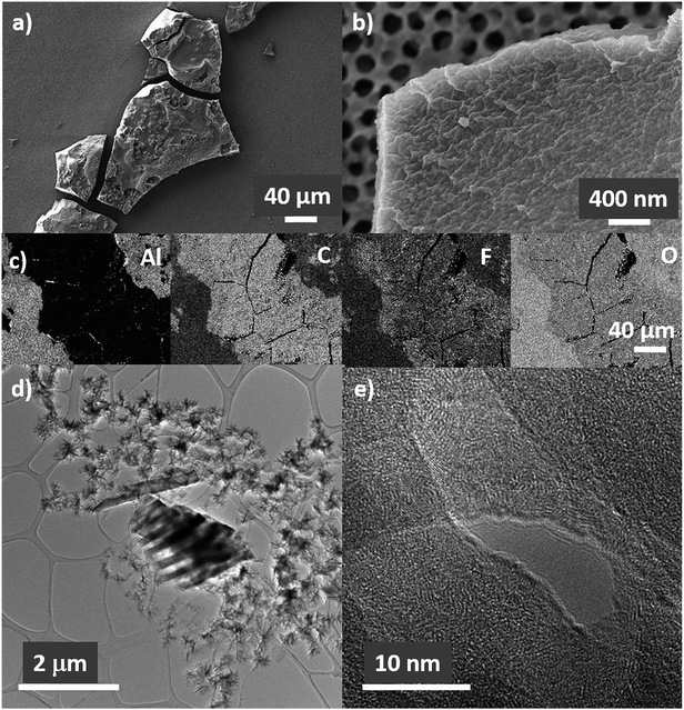
Growth of lithium deposits in the form of mossy lithium can be observed by ex situ SEM after disassembling Li|AAO: (1 M LiTf/triglyme)|Li cell both on the surface of lithium and on the AAO (Fig. 6a–c). The deposits are large particles (ca. 100 μm long), covered by a thin SEI layer. This is confirmed by energy-dispersive X-ray spectroscopy (EDS) elemental mapping images (Fig. 6c) showing that C, F, and O elements are evenly distributed on the particle surface. The structure of the deposit appears to be crystalline (Fig. 6d and e), with clear lattice fringes visible in high resolution TEM. However, the amount of the crystalline phase is not large enough to be detected by the XRD measurements. Such deposits might lead to cell short circuit if they penetrate the full length of AAO.
4. Conclusions
In this study, we report on LiTf/triglyme infiltrated in porous AAO as a possible electrolyte for lithium metal batteries. The beneficial adsorption of the anion on the surface of AAO leads to the increase of lithium transference number, tLi. The interfacial effect on the surface is higher at lower salt concentration and elevated temperature, with tLi reaching values of 80% at 80 °C in 1 M LiTf/triglyme, and 85% at room temperature in 0.02 M LiTf/triglyme. Interestingly, glyme-based AAO electrolyte seems to combine high lithium transference numbers with good stability with lithium electrodes.Glyme-based liquid–solid electrolytes proved to be more successful in stopping dendrite growth compared to their liquid counterparts infiltrated in glass fiber separators. However, at long stripping/plating times, mossy crystalline lithium deposits covered by an SEI can still be observed.
Conflicts of interest
There are no conflicts to declare.Acknowledgements
The authors thank Dr Igor Moudrakovski for the measurement of the 1H MAS-NMR spectra, Dr Helga Hoier for the XRD spectra, Peter Kopold for the TEM micrographs, Annette Fuchs for the SEM micrographs and titration experiments with AAO membranes, and Bernhard Fenk for the SEM of lithium deposits. Florian Kaiser, Armin Sorg, Uwe Traub and Udo Klock are acknowledged for their general technical support.References
- J.-M. Tarascon and M. Armand, Nature, 2001, 414, 359–367 CrossRef CAS PubMed.
- W. Xu, J. Wang, F. Ding, X. Chen, E. Nasybulin, Y. Zhang and J.-G. Zhang, Energy Environ. Sci., 2014, 7(2), 513–537 RSC.
- K. Zhang, G.-H. Lee, M. Park, W. Li and Y.-M. Kang, Adv. Energy Mater., 2016, 6(20), 1600811 CrossRef.
- M. Tikekar, S. Choudhury, Z. Tu and L. Archer, Nat. Energy, 2016, 1, 16114 CrossRef CAS.
- D. Lin, Y. Lui and Y. Cui, Nat. Nanotechnol., 2017, 12, 194–206 CrossRef CAS PubMed.
- H. Kim, G. Jeong, Y.-U. Kim, J.-H. Kim, C.-M. Park and H.-J. Sohn, Chem. Soc. Rev., 2013, 42, 9011–9034 RSC.
- X.-B. Cheng, J.-Q. Huang and Q. Zhang, J. Electrochem. Soc., 2018, 165, A6058–A6072 CrossRef CAS.
- R. Bhattacharyya, B. Key, H. Chen, A. S. Best, A. F. Hollenkamp and C. P. Grey, Nat. Mater., 2010, 9, 504 CrossRef CAS PubMed.
- J. Wandt, C. Marino, H. A. Gasteiger, P. Jakes, R.-A. Eichel and J. Granwehr, Energy Environ. Sci., 2015, 8, 1358 RSC.
- M. Wu, Z. Wen, Y. Liu, X. Wang and L. Huang, J. Power Sources, 2011, 196(11), 8091–8097 CrossRef CAS.
- G. Zheng, S. W. Lee, Z. Liang, H.-W. Lee, K. Yan, H. Yao, H. Wang, W. Li, S. Chu and Y. Cui, Nat. Nanotechnol., 2014, 9, 618–623 CrossRef CAS PubMed.
- N.-W. Li, Y.-X. Yin, C.-P. Yang and Y.-G. Guo, Adv. Mater., 2016, 28, 1853–1858 CrossRef CAS PubMed.
- A. Kozen, C.-F. Lin, O. Zhao, S. B. Lee, G. Rubloff and M. Noked, Chem. Mater., 2017, 29, 6298 CrossRef CAS.
- G. Wan, F. Guo, H. Li, Y. Cao, X. Ai, J. Qian, Y. Li and H. Yang, ACS Appl. Mater. Interfaces, 2018, 10(1), 593–601 CrossRef CAS PubMed.
- C.-P. Yang, Y.-X. Yin, S.-F. Zhang, N.-W. Li and Y.-G. Guo, Nat. Commun., 2015, 8058 CrossRef CAS PubMed.
- Q. Yun, Y.-B. He, W. Lv, Y. Zhao, B. Li, F. Kang and Q.-H. Yang, Adv. Mater., 2016, 28(32), 6932–6939 CrossRef CAS PubMed.
- L.-L. Lu, J. Ge, J.-N. Yang, S.-M. Cheng, H.-B. Yao, F. Zhou and S.-H. Yu, Nano Lett., 2016, 16(7), 4431–4437 CrossRef CAS PubMed.
- C. Monroe and J. Newman, J. Electrochem. Soc., 2005, 152, A396–A404 CrossRef CAS.
- R. Khurana, J. Schaefer, L. Archer and G. Coates, J. Am. Chem. Soc., 2014, 136(20), 7395–7432 CrossRef CAS PubMed.
- S.-O. Tung, S. Ho, M. Yang, R. Zhang and N. Kotov, Nat. Commun., 2015, 6, 6152 CrossRef CAS PubMed.
- C. Xu, Z. Ahmad, A. Aryanafar, V. Viswanathan and J. Greer, Proc. Natl. Acad. Sci. U. S. A., 2017, 114(1), 57–61 CrossRef CAS PubMed.
- L. Gireaud, S. Grugeon, S. Laruelle, B. Yrieix and J.-M. Tarascon, Electrochem. Commun., 2006, 8(10), 1639–1649 CrossRef CAS.
- S.-K. Jeong, H.-Y. Seo, D.-H. Kim, H.-K. Han, J.-G. Kim, Y. Lee, Y. Iriyama, T. Abe and Z. Ogumi, Electrochem. Commun., 2008, 10(4), 635–638 CrossRef CAS.
- J. Stark, Y. Ding and P. Kohl, J. Electrochem. Soc., 2011, 158(10), A1100–A1105 CrossRef CAS.
- G. Lane, A. Best, D. MacFarlane, M. Forsyth and A. Hollenkamp, Electrochim. Acta, 2010, 55(6), 2210–2215 CrossRef CAS.
- L. Suo, Y.-S. Hu, H. Li, M. Armand and L. Chen, Nat. Commun., 2013, 4, 1481 CrossRef PubMed.
- R. Bouchet, S. Maria, R. Meziane, A. Aboulaich, L. Lienafa, J.-P. Bonnet, T. Phan, D. Bertin, D. Gigmes, D. Devaux, R. Denoyel and M. Armand, Nat. Mater., 2013, 12, 452–457 CrossRef CAS PubMed.
- Y. Lu, Z. Tu and L. Archer, Nat. Mater., 2014, 13, 961–969 CrossRef CAS PubMed.
- Z. Tu, M. Zachman, S. Choudhury, S. Wei, L. Ma, Y. Yuang, L. Kourkoutis and L. Archer, Adv. Energy Mater., 2017, 7(8), 1602367 CrossRef.
- J.-K. Kim, D. Kim, S. Joo, B. Choi, A. Cha, K. Kim, T.-H. Kwon, S. Kwak, S. Kang and J. Jin, ACS Nano, 2017, 11(6), 6114–6121 CrossRef CAS PubMed.
- J. Jorne, Nano Lett., 2006, 6(12), 2973–2976 CrossRef CAS PubMed.
- C. Pfaffenhuber, F. Hoffmann, M. Fröba, J. Popovic and J. Maier, J. Mater. Chem. A, 2013, 1, 12560 RSC.
- C. Pfaffenhuber, M. Göbel, J. Popovic and J. Maier, Phys. Chem. Chem. Phys., 2013, 15(42), 18318 RSC.
- J. Popovic, G. Hasegawa, I. Moudrakovski and J. Maier, J. Mater. Chem. A, 2016, 4, 7135 RSC.
- J.-N. Chazalviel, Phys. Rev. A: At., Mol., Opt. Phys., 1990, 42, 7355 CrossRef CAS.
- M. Tikekar, L. Archer and D. Koch, J. Electrochem. Soc., 2014, 161, A847 CrossRef CAS.
- H. Wang, M. Matsui, H. Kuwata, H. Sonoki, Y. Matsuada, X. Shang, Y. Takeda, O. Yamamoto and N. Imanishi, Nat. Commun., 2017, 8, 15106 CrossRef PubMed.
- M. Petrowsky, R. Frech, S. N. Suarez, J. R. P. Jayakody and S. Greenbaum, J. Phys. Chem. B, 2006, 110(46), 230 CrossRef PubMed.
- J. Popovic, C. Pfaffenhuber, J. Melchior and J. Maier, Electrochem. Commun., 2015, 60, 195 CrossRef CAS.
- G. Girard, M. Hilder, D. Nucciarone, K. Whitbread, S. Zavorine, M. Moser, M. Forsyth, D. MacFarlane and P. Howlett, J. Phys. Chem. Lett., 2017, 121, 21087 CrossRef CAS.
- Q. Pang, X. Liang, A. Shyamsunder and L. Nazar, Joule, 2017, 1(4), 871 CrossRef CAS.
- M. Nojabaee, K. Müller, B. Fenk, U. Starke, J. Popovic and J. Maier, in preparation.
Footnote |
| † Electronic supplementary information (ESI) available. See DOI: 10.1039/c9ta03261d |
| This journal is © The Royal Society of Chemistry 2019 |

