
 Open Access Article
 This Open Access Article is licensed under a Creative Commons Attribution-Non Commercial 3.0 Unported Licence
Pillared-layered metal–organic frameworks for mechanical energy storage applications†
Jelle
Wieme
 a,
Sven M. J.
Rogge
a,
Pascal G.
Yot
b,
Louis
Vanduyfhuys
a,
Su-Kyung
Lee
c,
Jong-San
Chang
c,
Michel
Waroquier
a,
Guillaume
Maurin
b and
Veronique
Van Speybroeck
*a
a,
Sven M. J.
Rogge
a,
Pascal G.
Yot
b,
Louis
Vanduyfhuys
a,
Su-Kyung
Lee
c,
Jong-San
Chang
c,
Michel
Waroquier
a,
Guillaume
Maurin
b and
Veronique
Van Speybroeck
*a
aCenter for Molecular Modeling, Ghent University, Tech Lane Ghent Science Park Campus A, Technologiepark 46, 9052 Zwijnaarde, Belgium. E-mail: Veronique.VanSpeybroeck@UGent.be
bInstitut Charles Gerhardt Montpellier, Univ. Montpellier CNRS UMR 5253, CC1505, Université de Montpellier, Place Eugène Bataillon, F-34095 Montpellier Cedex 05, France
cResearch Center for Nanocatalysts, Korea Research Institute of Chemical Technology, Yusung, Daejeon 305-600, Korea
First published on 30th September 2019
Abstract
Herein we explore the unique potential of pillared-layered metal–organic frameworks of the DMOF-1 family for mechanical energy storage applications. In this work, we theoretically predict for the guest-free DMOF-1 a new contracted phase by exerting an external mechanical pressure of more than 200 MPa with respect to the stable phase at atmospheric pressure. The breathing transition is accompanied by a very large volume contraction of about 40%. The high transition pressures and associated volume changes make these materials highly promising with an outstanding mechanical energy work. Furthermore, we show that changing the nature of the metal allows to tune the behavior under mechanical pressure. The various phases were revealed by a combination of periodic density-functional theory calculations, force field molecular dynamics simulations and mercury intrusion experiments for DMOF-1(Zn) and DMOF-1(Cu). The combined experimental and theoretical approach allowed to discover the potential of these materials for new technological developments.
1 Introduction
The exceptional flexibility displayed by breathing metal–organic frameworks (MOFs) has attracted much attention over the past few years.1–5 Such materials – belonging to the class of soft porous crystals2 – feature an enormous shift in volume upon external stimuli without breaking chemical bonds. Various triggers such as temperature, pressure and guest adsorption have been used to initiate a breathing transition in a limited number of frameworks (e.g.ref. 6–9). The drastic change of the volume accompanying the breathing transition makes these peculiar materials extremely enticing for a large variety of applications such as gas storage, separation and detection,10–12 controlled drug release13 and mechanical energy storage.14,15Given these remarkable properties, extensive efforts have also been spent to unravel the origin of flexibility from a theoretical point of view. Some of us recently showed that fundamental insight into the macroscopic conditions at which MOFs display flexibility can be gained through knowledge of the thermodynamic potential.5 However, despite the enormous progress made in recent years, the automated, computer-aided detection of flexible materials is still very challenging.16,17 For other properties such as gas storage and separation, high-throughput screening allowed to identify new structures that outperform the current materials (e.g.ref. 18–20), but most computational studies on flexible materials still tend to focus only on understanding the flexibility of specific case studies (e.g.ref. 21–27).
In this study, we investigate the dehydrated DMOF-1 framework28,29 with either copper or zinc at the metal nodes belonging to the subclass of pillared-layered MOFs.30,31 This class of hybrid porous materials has already demonstrated to be an excellent testing platform for flexible behavior with a high tunability of physical and chemical properties through standard MOF synthesis routes such as functionalization or substitution of the metal and/or organic ligand. In DMOF-1, the two-dimensional layers are formed by paddle wheels composed of divalent metal cations, which are bridged by 1,4-benzenedicarboxylate (BDC) organic linkers (Fig. 1). The layers are connected through 1,4-diazabicyclo[2.2.2]octane (DABCO) pillar ligands via the axial sites of the paddle wheels. This material has been synthesized with various types of metal ions (Fe,32 Co,33,34 Ni,35,36 Cu,28 Zn29) and mixed-metal variants exist.37 While theoretical investigations of DMOF-1 are relatively limited,5,17,21,38,39 the unusual and reversible breathing behavior has been highlighted by several experimental groups.29,40–54 On the one hand, with guests present in the pores, DMOF-1(Zn) was found to contract upon adsorption. Specific guest molecules such as benzene, methanol, ethanol and isopropanol (IPA) trigger breathing,29,40,42,50 while N,N-dimethylformamide (DMF) distorts the structure in a different way.29,50 Nevertheless, this material is rather weakly responsive to most guests. On the other hand, no temperature-induced breathing transitions have been reported for this jungle-gym-type framework. Kim et al. did find that the Zn variant displays a slight anisotropic negative thermal expansion between 150 K and 298 K with a symmetry group change at low temperatures.50 The thermo-responsive and guest-dependent behavior of DMOF-1 – especially for the Zn variant – can thus be considered well-studied from an experimental point of view. More interestingly, enormous thermal expansion behavior and breathing transitions could be obtained when functionalizing the BDC linker.39,48,51,53 Particularly, the attachment of pendant alkoxy chains greatly modified the structural flexibility. Functionalization also allowed to influence the guest-dependent behavior.41–44,47,49,51,52 Very recently, Fischer and co-workers discussed into detail the significant impact of the metal ion on the breathing mechanisms in a functionalized DMOF-1.53 Previous studies highlighted how the threshold gas pressure and transition temperature for the breathing transition can be tuned by the choice of the functional groups and metal ion. So far the response of this MOF upon mechanical pressure has barely been investigated.5,55–57
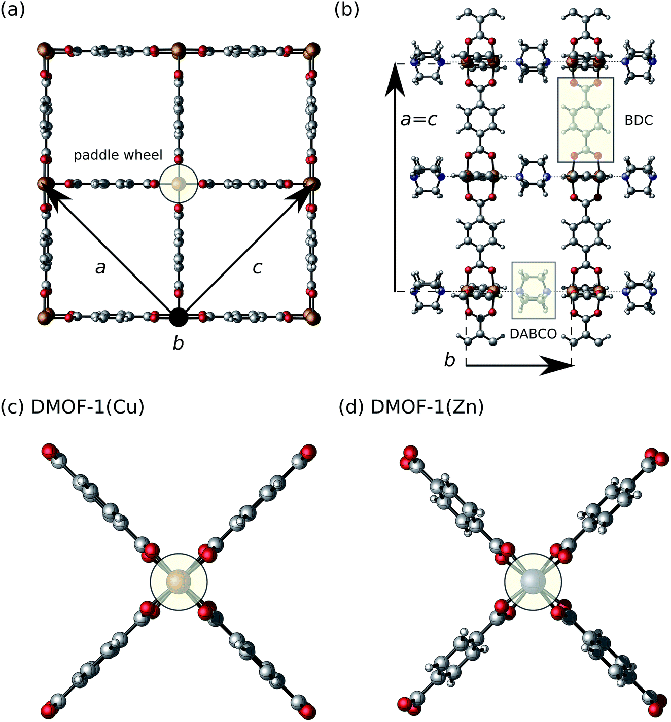 | ||
| Fig. 1 Molecular representation of the open-pore phase of DMOF-1 and its building blocks (paddle wheel, 1,4-benzenedicarboxylate (BDC) and 1,4-diazabicyclo[2.2.2]octane (DABCO)). The definition of the unit cell parameters is indicated. (a) Two-dimensional layer formed by paddle wheels connected through BDC organic linkers. The a and c lattice vectors are aligned along the diagonals of the pores. (b) The connection of the two-dimensional layers through DABCO pillar ligands along the b-direction. (c and d) Paddle wheel present in the equilibrium unit cell of (c) DMOF-1(Cu) and (d) DMOF-1(Zn), obtained at the PBE + D3(BJ) level of theory at 0 K. | ||
Therefore, we want to further explore the potential of these highly tailorable frameworks for mechanical energy storage. To this end, we examined the pressure-induced flexibility of empty DMOF-1(Zn) and DMOF-1(Cu) through a combination of theoretical and experimental techniques. Using first-principles and force field simulations, we predict a breathing transition for both prototypical pillared-layered materials with very appealing features such as a high transition pressure and a massive volume contraction. Subsequently, to validate these theoretical findings, mercury intrusion experiments have been accomplished on both variants. This technique was originally used to detect pressure-induced structural transitions in several wine-rack MOFs,8,14,15,58–61 and it has been applied to characterize the structural transitions in other flexible frameworks such as ZIF-4 (ref. 62) and DUT-48/49.63 The experiments confirmed some of the interesting features found by theory. This study highlights the complementary power of theory and experiment to unravel the behavior of flexible MOFs for promising technological applications.
2 Methods
2.1 Theory/computational details
DMOF-1 was investigated using two types of simulation strategies, namely periodic density-functional theory (DFT) calculations and force field simulations which allow to simulate at realistic conditions of pressure and temperature. The periodic plane-waves DFT calculations were performed with the Vienna Ab initio Simulation Package (VASP)64 using the projector-augmented wave (PAW) method.65 We used the PBE66 exchange–correlation functional combined with the DFT-D3 dispersion scheme using Becke–Johnson damping.67,68 We recently showed that PBE + D3(BJ)ATM resulted in the best agreement with a high-level many-electron treatment for an energy profile as a function of the volume for a breathing MOF.25 Therefore, we added three-body Axilrod–Teller–Muto (ATM) contributions69,70 (D3(BJ)ATM) to the energy with the DFT-D3 program as they have not yet been implemented in VASP. The energy profile as a function of the volume was constructed by fixed-volume relaxations in which the atomic positions and cell shape were optimized.15,71 We also calculated the dynamical matrix at the Γ-point for the stable open-pore phase of DMOF-1(Zn). More technical details on the DFT simulations can be found in the ESI.†For the force field simulations, a new force field was derived from the dynamical matrix with QuickFF72,73 for DMOF-1(Zn) including covalent, electrostatic and van der Waals interactions. The covalent interactions were fitted with QuickFF and include anharmonic bond and bend terms, out-of-plane terms, dihedral terms, and cross terms. The electrostatic interactions are modeled with Gaussian smeared MBIS74 point charges, which were derived with Horton.75 The MM3-Buckingham potential76,77 is used to model the van der Waals interactions. The force field parameters and detailed force field energy expression are included in the ESI Section II.† The force field is able to qualitatively describe the flexibility of DMOF-1(Zn) under mechanical pressure. An exact quantitative correspondence between the DFT and the force field energy curves at 0 K is very challenging. First, the force field only includes pairwise dispersion interactions and therefore lacks potentially important many-body dispersion effects at low volumes included in our DFT results.25 Furthermore, the force field was fitted on the open-pore phase of DMOF-1(Zn) and is intrinsically less accurate for anharmonic atomic displacements in the low-volume region. A more detailed comparison and validation is taken up in the ESI (Section II.B†). The DMOF-1(Zn) force field was used to perform molecular dynamics (MD) simulations with Yaff78 in both the (N, V, σa = 0, T) and (N, P, σa = 0, T) ensembles.23,79 Simulations were carried out for different volumes at a temperature of 150 K, 300 K and 450 K allowing the cell shape to fluctuate.23,79 We constructed the pressure profile P(V) and Helmholtz free energy profile F(V) as a function of the volume for these temperatures. The procedure to derive these profiles is explained in detail elsewhere.5,23 Additional computational details are given in the ESI.†
2.2 Experiments
DMOF-1(Zn) was synthesized from a mixture of terephthalic acid (H2BDC) (3.37 mol, 560 mg), DABCO (1.67 mmol, 187 mg) and Zn(NO3)2·6H2O (3.36 mmol, 1000 mg) in 40 mL of DMF in a conical flask and stirred at room temperature for 20 minutes, followed by a sonication of 20 minutes. The mixture was transferred into a Teflon-lined autoclave and heated to 120 °C for 48 hours. Thereafter, the colorless crystalline precipitate was cooled down to room temperature. The as-synthesized DMOF-1(Zn) was further purified by a two-step procedure using DMF and hot ethanol. To remove the residual unreacted substances, the solid was immersed into DMF for 3 hours and subsequently in hot ethanol at 60 °C for 3 hours. The highly purified solid was evacuated in vacuum at room temperature for 12 hours. DMOF-1(Cu) was synthesized following the same protocol starting with a mixture of BDC (3 mmol, 498 mg), DABCO (2.49 mmol, 279 mg) and Cu(NO3)2·3H2O (3 mmol, 725 mg) in 60 mL of DMF.Both DMOF-1(Zn) and DMOF-1(Cu) samples were evacuated under secondary vacuum during 8 hours at 150 °C. The sample preparations were performed using a glove box (Jacomex P-BOX) under argon atmosphere (H2O < 1 ppm). The structural features of both DMOF-1 solids were investigated by laboratory powder X-ray diffraction (PXRD) using a PANalytical X'Pert equipped with an X'Celerator detector and a Si (111) monochromator (Cu-Kα1 wavelength, λ = 1.54059 Å with an operating voltage of 40 kV and a beam current of 40 mA). The samples were loaded into a 1 mm glass capillary in a glove box and sealed before collecting their PXRD patterns (ESI Fig. 12 and 13†). These diffraction patterns were successfully indexed in the tetragonal system with the space group P4/nbm (no. 125). The resulting unit cell parameters (ESI Table VI†) and associated volume (DMOF-1(Zn): 2301.1(1) Å3, DMOF-1(Cu): 2266.2(1) Å3) were obtained using a LeBail fit by the Jana2006 software.80
Compression of the two solids was carried out using mercury intrusion. To avoid rehydration, the powders were loaded into a penetrometer of 3.1126 mL volume with a stem volume of 0.4120 mL into a glove box (Jacomex P-BOX) under argon atmosphere H2O < 5 ppm. The mercury intrusion experiments were carried out using a Micromeritics AutoPore IV 9500 allowing a range of applied pressure from 0.003 MPa to 420 MPa. Prior to the experiments, the powder was outgassed at 6.5 Pa during 15 minutes. The collected volume of intruded mercury was corrected by a blank recorded under the same temperature and pressure conditions using the same penetrometer to obtain the absolute contracted volume as a function of the applied pressure. Two compression–decompression cycles were collected in this range of pressure for two distinct scenarios: (i) consecutive cycles and (ii) cycles separated by a time interval of 48 hours (ESI Fig. 14 and Table VI†).
After the compression by mercury intrusion the powders of both solids were carefully collected, separated from the mercury and their structural features were analyzed with PXRD following the same protocol described above (ESI Fig. 15 and 16†).
More details on the experiments can be found in the ESI.†
3 Results and discussion
3.1 Equilibrium structures of DMOF-1(Zn) and DMOF-1(Cu)
First, we optimized the crystallographic unit cells of DMOF-1(Zn)29 and DMOF-1(Cu)28 in the open-pore (op) state with cuboidal-shaped pore channels by constructing a local energy profile as a function of the volume using DFT calculations71 (ESI Fig. 1†). The op state of DMOF-1(Zn) at 0 K contains twisted DABCO pillar ligands, and twisted and slanted BDC linkers in agreement with the crystal structure solved experimentally50,81 (Fig. 1(c) and (d)). Our optimized structure of DMOF-1(Cu) does not feature such pronounced local symmetry breakings as the zinc variant. While the equilibrium structures of the two metal variants show some differences, the energy profiles near equilibrium are very similar (ESI Fig. 1†). An equation of state is fitted following the procedure of Vanpoucke et al.71 and the resulting properties are tabulated in Table 1. The Zn variant has a slightly larger unit cell volume and it is less rigid, as reflected in the equilibrium volume V0 and bulk modulus B0, respectively. The simulated values are in good agreement with the experimental data (at room temperature) obtained from PXRD (volume) and mercury porosimetry (bulk modulus) (Table 1). In particular, it is experimentally confirmed that the bulk modulus for DMOF-1(Cu) is higher than for its Zn-analogue. The higher rigidity of the copper paddle wheel as compared to a zinc paddle wheel was previously ascribed to electronic effects38,53 such as orbital directing effects only present in the copper variant. For the latter, we considered various possible magnetic configurations (ESI Section I.C†), as each metal ion has one unpaired d-electron. This did not have much influence on V0 and B0 as found for other copper paddle-wheel MOFs (e.g. HKUST-1 (ref. 82)), but in contrast to the flexible MIL-47(V) with a magnetic 1D chain.83 Our computational results confirm that an antiferromagnetic Cu–Cu coupling in the paddle wheel is preferred, together with negligible ferromagnetic interactions along the BDC and DABCO linkers (ESI Section I.C†), which was also measured by Kozlova et al.84 The obtained equilibrium lattice parameters of DMOF-1(Cu/Zn) are reported in Table VII in the ESI.† Our DFT results slightly overestimate the experimental lattice parameters (definition see Fig. 1), but we find overall a good agreement and a reproduction of the qualitative trends (aCu ≈ cCu < aZn ≈ cZn, bCu > bZn and VCu < VZn). This emphasizes that our computational DFT approach succeeds in reproducing the experimentally reported structural features.| Material | V 0 (Å3) | B 0 (GPa) | B 1 (—) | ||
|---|---|---|---|---|---|
| Theory | Exp. | Theory | Exp. | Theory | |
| DMOF-1(Cu) | 2318 | 2266 | 16.4 | 18.8 | 11.0 |
| DMOF-1(Zn) | 2334 | 2301 | 13.7 | 16.9 | 0.2 |
3.2 Prediction of pressure-induced breathing
Beyond this stable op phase at 0 K, DMOF-1 and functionalized forms have displayed different metastable states under influence of temperature and guests as mentioned in the introduction. To clearly distinguish between the various states observed in our calculations, we have extended the nomenclature of the possible configurations of the material as shown in Fig. 2. We differentiate between the open pore (op), large pore (lp), narrow pore (np) and closed pore (cp) states for which the pore angle α (definition see Fig. 2) and unit cell volume decrease. In the stable op state, the pore channels have a rectangular cross section and the lattice parameters a and c are approximately equal (Fig. 1). Previous studies showed that various guest molecules (e.g. benzene29) may cause a contraction of α, with a symmetry lowering from a tetragonal (a ≈ c) to an orthorhombic (a > c) lattice. Following our nomenclature, guest-induced breathing leads to a lp state with lozenge-shaped pore channels. The pore angle remains higher than 67 degrees, which is to the best of our knowledge the lowest value reported for DMOF-1 in the presence of guests.45 We denote the state with an even lower α as the np state, which is the continuation of the lp at lower volumes where no guests can enter DMOF-1. Such large contractions have, however, been reported when functionalizing the organic linkers.47 Lastly, the cp state represents the configuration in which the channels become distorted and deviate from a lozenge. Such distortions were already found in other MOFs with one-dimensional pore channels such as MIL-53(Sc) and MIL-53(Al)-ADP.85,86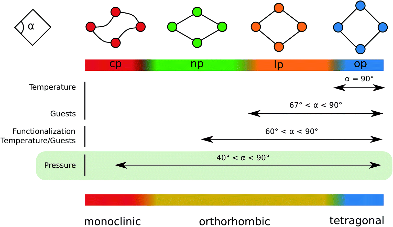 | ||
| Fig. 2 Schematic overview of the reported flexibility in DMOF-1 illustrated as a function of the pore angle α. Our definition of the different states is indicated. The crystal system of the different states is indicated at the bottom, distinguishing between tetragonal (op), orthorhombic (lp and np) and monoclinic (cp). | ||
We now focus on the intrinsic flexibility of the empty DMOF-1 framework. This is first achieved by constructing the energy profile as a function of the volume using DFT calculations at 0 K.15,25,71 These DFT E(V) profiles are shown in the top left panel of Fig. 3 for DMOF-1(Zn) and DMOF-1(Cu), together with the indication of various states as introduced earlier. It is immediately clear that the energy curves strongly resemble the breathing curves of other flexible MOFs.5 Recently we have shown that the shape of the Helmholtz free energy profile is indicative for the expected flexible behavior under the influence of various triggers.5,25,87 The now observed curves do not include temperature corrections, yet they already give an indication of the expected mechanical behavior.
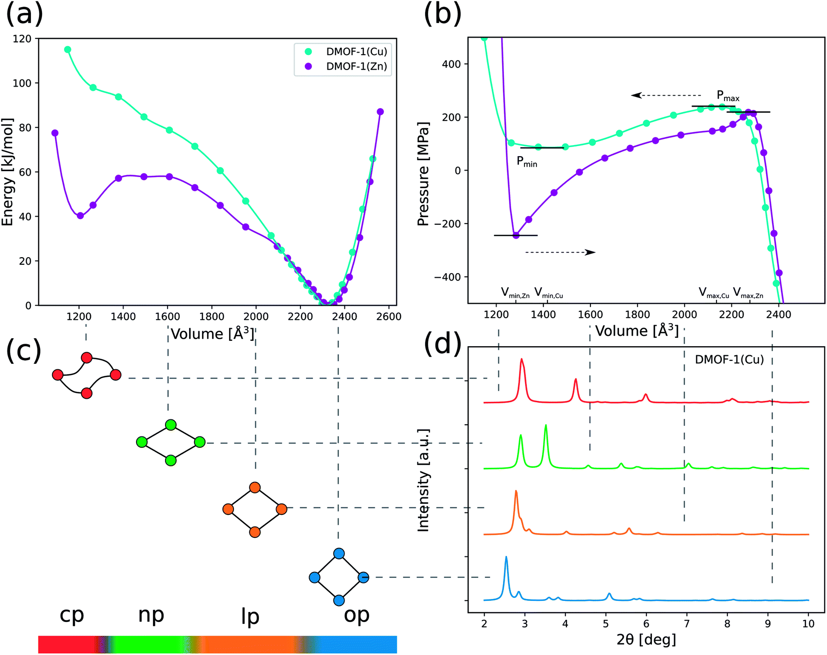 | ||
Fig. 3 (a) DFT energy profiles E(V) as a function of the volume for DMOF-1(Cu) and DMOF-1(Zn) at 0 K (PBE + D3(BJ)ATM). The lines only represent a guide to the eye. (b) Pressure profiles P(V) (at 0 K) as a function of the volume obtained by numerically deriving the energy profiles via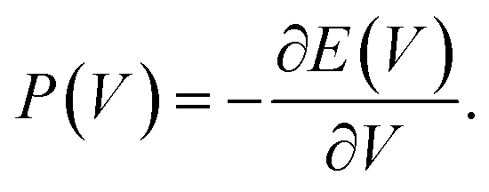 Pmax is 239 MPa for DMOF-1(Cu) and 222 MPa for DMOF-1(Zn). Pmin is 86 MPa for DMOF-1(Cu) and −238 MPa for DMOF-1(Zn). (c) The definition of the states (open pore (op), large pore (lp), narrow pore (np) and closed pore (cp)) used in this work is inspired by the pore angle α as defined in Fig. 2. (d) Simulated XRD patterns for different representative phases of DFT-optimized DMOF-1(Cu) (λ = 0.4859 Å). Pmax is 239 MPa for DMOF-1(Cu) and 222 MPa for DMOF-1(Zn). Pmin is 86 MPa for DMOF-1(Cu) and −238 MPa for DMOF-1(Zn). (c) The definition of the states (open pore (op), large pore (lp), narrow pore (np) and closed pore (cp)) used in this work is inspired by the pore angle α as defined in Fig. 2. (d) Simulated XRD patterns for different representative phases of DFT-optimized DMOF-1(Cu) (λ = 0.4859 Å). | ||
More specifically and according to our earlier classification,5 DMOF-1(Cu) has a Type III energy profile and corresponds to a lossy spring with a back and forth transition from one phase to the other when increasing or releasing the mechanical pressure. Fig. 3(b) displays the pressure profile P(V) as a function of the volume, which can be derived by differentiation of the simulated DFT energy profile at 0 K. These calculations predict that at a pressure of about 240 MPa (Pmax for DMOF-1(Cu)) the structural transition takes place from the op phase towards a dense state with a unit cell volume of about 1200 Å3, which represents a remarkable volume contraction of 40%. A new dense configuration appears in a cp state, which is only stable at high pressures. The simulations for DMOF-1(Cu) thus predict that this structural transformation is reversible and displays a hysteresis of about 150 MPa. According to our 0 K DFT calculations we find a cp like state with distorted channels. An example is shown in ESI Fig. 4.† However, it needs to be validated by simulations at higher temperatures to what extent such shapes are still valid (vide infra).
Based on its E(V) curve, DMOF-1(Zn) can be classified as a Type IIa material, where the material suddenly switches to a contracted state but never returns. The pressure profile reveals a slightly lower critical pressure Pmax (≈220 MPa) as compared to DMOF-1(Cu). Moreover, the dense state is even found to be a metastable phase at 0 K in this case. Therefore, this material is predicted to behave as a nanoshock absorber as it displays an irreversible pressure-induced transition (a negative Pmin is experimentally not yet accessible).5
Significant energetic differences can also be observed in the dense structure of the two DMOF-1 materials (Fig. 3(a)). The dense state of the Cu variant is much less stable than the Zn variant (±100 kJ mol−1 with respect to the stable open phase versus ±40 kJ mol−1), which was also reflected in the bulk modulus at 0 K (Table 1). This clearly emphasizes that changing the nature of the metal allows to tune the mechanical behavior of DMOF-1 (lossy spring or nanoshock absorber).
Finally, a valuable figure of merit to characterize the potential of a MOF for mechanical energy storage applications is the relation PmaxΔV for energy work. It presents a theoretical upper bound for the energy stored during the pressure-induced breathing process. As both the predicted transition pressure Pmax (more than 200 MPa) and the associated volume change (≈40%) of DMOF-1 are among the highest reported so far for flexible frameworks, this material could thus potentially be interesting for mechanical energy storage. We find a predicted energy work of approximately 119 J g−1 and 130 J g−1 for DMOF-1(Cu) and DMOF-1(Zn), respectively.
3.3 Molecular-level characterization of the phase transition at operando conditions
To extend our predictions towards experimental conditions at higher temperature, we performed force field MD simulations as described in the Methods section on DMOF-1(Zn) with a new QuickFF force field72,73 The Helmholtz free energy profiles are shown in Fig. 4. Only in cases where DMOF-1 materials were additionally functionalized, for example with pendant alkoxy groups,39,48,51,53 the relative stability between the various phases could be drastically changed. In these specific cases, additional interactions between the functional groups allowed to stabilize the contracted phase at low temperatures. The op state could then only be retrieved at high temperatures. A similar balance between dispersion and entropy was recently rationalized by some of us on the MIL-53(Al).25 More important for the current study, however, is that we find that both transition pressures Pmax and Pmin increase with temperature from 169 MPa at 150 K to 200 MPa and 210 MPa at 300 K and 450 K, respectively (Fig. 4), and that the metastable dense phase of DMOF-1(Zn) is expected to disappear. The PmaxΔV energy work increases from 91 J g−1 to 108 J g−1 over this temperature range.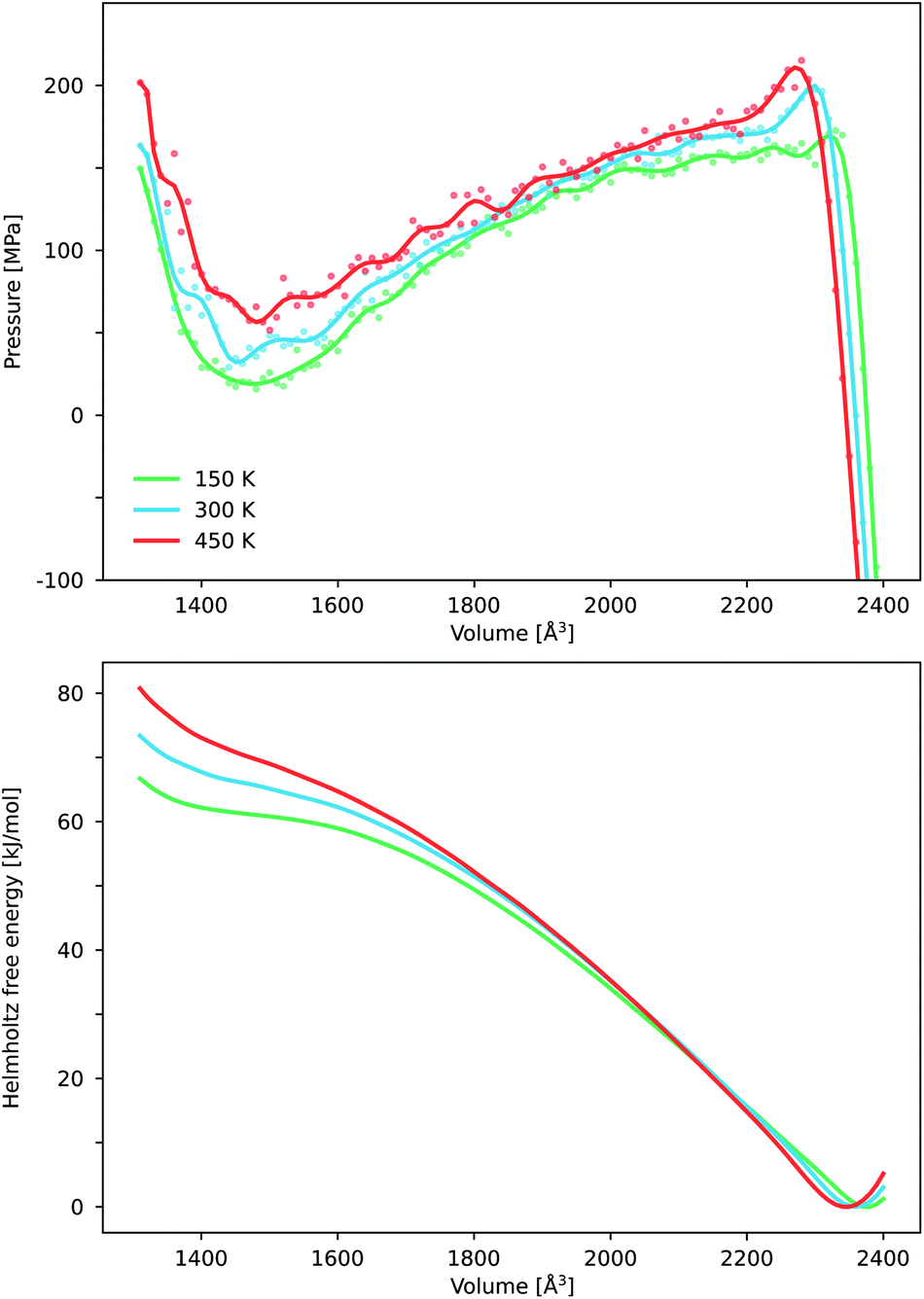 | ||
| Fig. 4 The pressure P(V) and Helmholtz free energy F(V) profiles as a function of the volume obtained through force field MD simulations for DMOF-1(Zn) at 150 K, 300 K and 450 K. | ||
Until now, we have focused on the macroscopic conditions of breathing in DMOF-1. In order to gain more molecular-level insight in the pressure-induced breathing process, we studied the behavior of some important structural parameters as a function of the volume. A first impression is achieved through monitoring the final structures of the geometry optimizations used to construct the DFT energy profile as a function of volume for both the copper and zinc variants at 0 K. This procedure allows us to easily examine the evolution of the shape of the unit cell and the results are displayed in Fig. 5. In the stable op phase, both materials adopt a tetragonal lattice system. When the volume decreases, the system goes abruptly over to an orthorhombic symmetry (a ≠ c), as the pores start to anisotropically contract instead of isotropically shrinking in the 2D layer. At very small volumes – when the pores become distorted, i.e. the cp phase – the structure deviates from an orthorhombic symmetry. During the entire transition process from the op to the cp structure, the metal–DABCO axis remains nearly constant, indicating that the volume reduction entirely results from breathing in the 2D layers. On the molecular level, the pores mainly shrink due to a knee-cap motion, accompanied by slanting of the BDC linkers, which is shown in the right panel of Fig. 5. This is suggested by the evolution of the dihedral M–O–C–C angle in the DFT optimized structures. This dihedral angle was previously identified as an important internal coordinate for the breathing motion in members of the MIL-53 family.23,88 Contrarily, the square-planar coordination environment around the copper and zinc ions remains relatively intact on average.
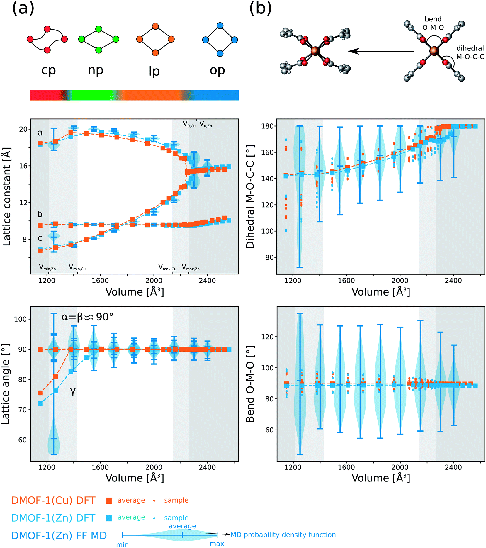 | ||
| Fig. 5 The lattice parameters and internal coordinates of DMOF-1(Cu) and DMOF-1(Zn), obtained through DFT optimization at 0 K. The DMOF-1(Zn) force field (FF) molecular dynamics (MD) results are indicated via violin plots. They show the probability density function of the property obtained through (N, V, σa = 0, T) simulations at different volumes and at 300 K. (a) Evolution of the lattice parameters (as defined in Fig. 1) as a function of the volume. The different states (cp, np, lp and op) are again schematically indicated. (b) Evolution of important internal coordinates as a function of the volume. The definition of the bend and dihedral are indicated in the top right panel. The transparent grey regions indicate the mechanically (meta)stable volume regions for pressures above Pmin and below Pmax, as obtained in Fig. 3(b). The light grey region only encompasses DMOF-1(Cu), while the darker region includes both DMOF-1(Zn) and DMOF-(Cu). | ||
Essential insights in the pressure-induced breathing process at operating conditions can be obtained by looking at the system at room temperature. Then, the system runs through different molecular configurations during the energetically preferred knee-cap motion according to our force field MD simulations on DMOF-1(Zn). Although the lattice constants vary only mildly at room temperature, the internal coordinates describing the structure of the paddle wheels, i.e. O–M–O bends, can fluctuate in a surprisingly wide range from 60 degrees to 125 degrees. For the cp state, the distribution becomes even wider. We display this by violin plots in Fig. 5, which show the probability density function as obtained via (N, V, σa = 0, T) simulations at 300 K. This unveils that a static picture (DFT at 0 K) might be misleading, and that at realistic conditions both knee-cap and paddle wheel deformations are present during the breathing process.
We further analyzed the structural properties based on our force field simulations. Focusing on the evolution of the symmetry of the DMOF-1(Zn) unit cell as a function of the volume at 300 K, as indicated in Fig. 6, a similar picture as the one at 0 K emerges. Starting at high volumes, the material adopts the tetragonal crystal system (op state). When decreasing the volume, the material undergoes a tetragonal-to-orthorhombic symmetry breaking around 2300 Å3. As the states with an orthorhombic symmetry are mechanically unstable (positive ∂P/∂V slope in Fig. 4) this volume region is not directly attainable by applying a pressure to the material, as also schematically depicted in Fig. 2. Finally when decreasing the volume below ca. 1300 Å3, the material undergoes a further symmetry breaking towards a monoclinic phase, observed in the mechanically stable cp state. Hence, while the inclusion of temperature at operating conditions clearly allows for larger fluctuations in the internal coordinates, the sequence of phases and crystal systems at room temperature is the same as those observed earlier with DFT at 0 K.
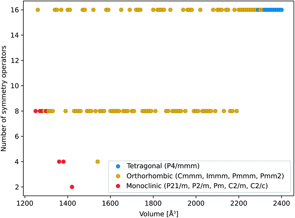 | ||
| Fig. 6 Evolution of the DMOF-1(Zn) cell symmetry at 300 K, as indicated by the number of symmetry operators as a function of the volume during the breathing process obtained through (N, V, σa = 0, T) simulations. For each volume, the crystal system of the material is indicated with a color code, distinguishing between the tetragonal (op), orthorhombic (lp and np) and monoclinic (cp) crystal systems. | ||
3.4 Experimental contraction of DMOF-1(Zn) and DMOF-1(Cu) through mercury intrusion measurements
Motivated by the predictions so far, we investigated the isostructural DMOF-1(Zn) and DMOF-1(Cu) materials using mercury intrusion experiments to verify the possible contraction of the two pristine phases under mechanical pressure and to further confirm their promise for mechanical energy storage. Fig. 7 shows the evolution of the cumulative volume of intruded mercury as a function of the applied pressure for the two materials. Two consecutive intrusion–extrusion, i.e., compression–decompression, cycles, from 10−3 MPa to 420 MPa, were applied to the samples. While the first two steps of the curve at 0.01 MPa and ∼12 MPa correspond to the compaction of the powder and the filling of interparticle grains, the increase in volume of mercury observed at ∼51 MPa and ∼193 MPa for DMOF-1(Zn) and DMOF-1(Cu), respectively, can only be associated with a contraction of these microporous materials since Hg does not enter the pores. The resulting volume variations (ΔV) of 0.59 mL g−1 and 0.41 mL g−1 correspond to a contraction of ∼48% and ∼34% of the unit cell volume for DMOF-1(Zn) and DMOF-1(Cu), respectively. It can be noted that the transition pressure (Pmax) of DMOF-1(Cu) is significantly higher than the one of DMOF-1(Zn). The trend that the copper version is more rigid than the zinc variant is qualitatively consistent with the predictions, and with the simulated and experimental bulk moduli. Furthermore, we observed that this structural change is irreversible for both materials as evidenced by the superposition of the experimental data collected during the first decompression and the second compression/decompression steps. To probe possible kinetic effects on the (ir)reversibility of the structural contraction, two compression–decompression cycles were performed with a time interval of 48 hours between the first and the second cycle (ESI Fig. 14†). Both experimental conditions lead to very similar Hg-porosimetry curves (transition pressure, volume change) for both solids, indicating that more time does not allow a reopening of the contracted structures.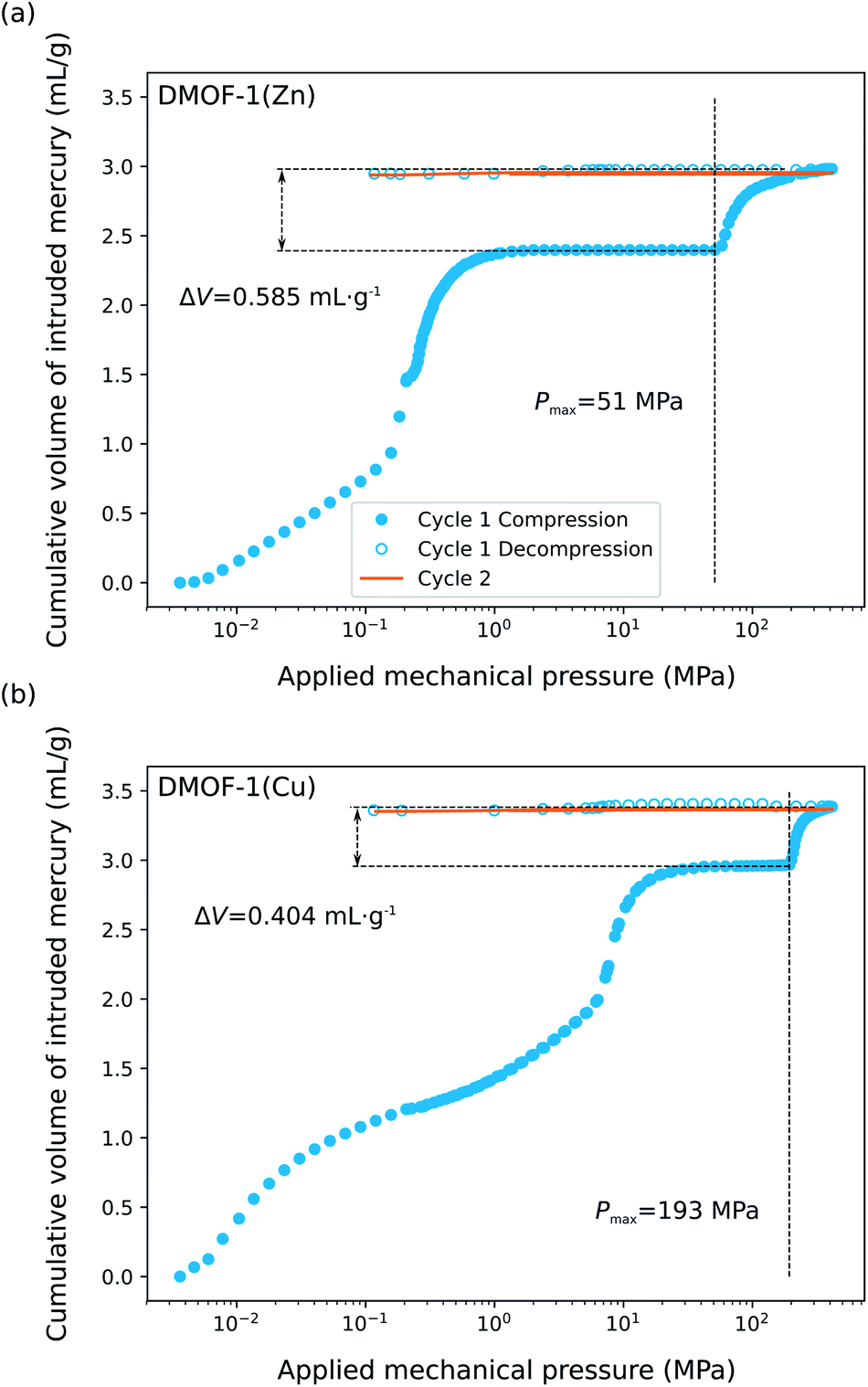 | ||
| Fig. 7 Cumulative volume of intruded mercury in an intrusion–extrusion experiment with two consecutive cycles as a function of the applied mechanical pressure obtained for the (a) DMOF-1(Zn) and (b) DMOF-1(Cu) sample. The measured transition pressure Pmax and associated volume change are indicated in the figure. The results of the two cycles separated by a time interval of 48 hours are given in ESI Fig. 14.† | ||
Considering the initial mass of the samples and the unit cell volumes determined from our laboratory PXRD (Table 1), the volumes of the contracted phases are expected to be about 1200 Å3 (DMOF-1(Zn)) and 1500 Å3 (DMOF-1(Cu)), which seem to be situated around the theoretical volumes at Pmin. The PΔV energy work associated to this structural contraction can be estimated to be about 30 J g−1 and 80 J g−1. The latter value is among the highest performances reported for a MOF so far, which makes DMOF-1(Cu) highly attractive for mechanical energy storage applications, and more specifically as a nanoshock absorber.5
Since the Hg-induced structural transformation of the two materials is irreversible, we collected the PXRD patterns of the corresponding powders obtained after compression. ESI Fig. 15 and 16† show that this irreversible contraction is accompanied by an amorphization of the polycrystalline sample, which makes it impossible to determine the unit cell parameters of the experimentally contracted structure. This behavior is similar to a very recent study some of us performed on the pressure-induced contraction of DUT-48/DUT-49.63 In this specific case, Hg-porosimetry confirmed the characteristics of the theoretically predicted transition (the relative volume contraction and the transition pressure), but the contracted structure previously evidenced by in situ gas adsorption89 was not observed after mercury intrusion. For DMOF-1, it is known that under the influence of specific guests (e.g. water vapor, air), the 3D structure can break down at the pillar ligands towards 2D layers.90–92 Additionally, mechanical nano-indentation experiments have shown that the direction along the DABCO linker is brittle and can start to plastically deform,55 which could also explain the structural collapse and irreversibility of DMOF-1. In our case, it remains to be verified if the amorphization takes place during the structural contraction or due to compression beyond the contracted phase as the applied pressure during an intrusion experiment is varied up to 420 MPa.
Given these experimental findings, we can return to our computational predictions and evaluate their validity. As the powders after Hg-intrusion have become amorphous, we cannot conclusively confirm the reversible or irreversible nature of the structural transition. Nevertheless, the experimentally measured volume contractions for both materials are in agreement with the simulations. The computational transition pressure is slightly overestimated (239 MPa versus 193 MPa) for DMOF-1(Cu). For DMOF-1(Zn), in contrast, theory did predict an irreversible crystalline transformation, but the experimental transition pressure does not coincide well with the DFT or force field MD simulations. This discrepancy could also be related to the difficulty of getting accurate predictions for the relative stability between different phases without the use of computationally very heavy methodologies,25 or by other effects present in the sample which are not well understood. For instance, the crystal size has shown to modify the hysteresis behavior and corresponding threshold values in flexible MOFs in different ways.93–95
3.5 Theoretical characterization of the contracted phase
To further characterize the evolution of DMOF-1 under pressure, we calculated the XRD patterns of our DFT-optimized structures (at 0 K) as a function of the volume to predict the evolution of an ideal in situ high-pressure powder X-ray diffraction experiment. These theoretical results may serve as a useful tool in future experimental characterization studies targeted to unravel the contracted phase. Based on the estimated volumes from the mercury intrusion experiments, we cannot distinguish between a cp or a np state. Below, we only discuss the results for DMOF-1(Cu), as the predicted behavior of the Zn variant is nearly identical (ESI Fig. 10†). In Fig. 3(d), the simulated XRD pattern is indicated for a representative structure with different characteristic volumes as obtained from 0 K DFT simulations. Our simulated low angle XRD patterns illustrate that especially the first peaks should change in relative intensity when the structure contracts. This trend is also observed in experimental in situ studies of guest- or temperature-induced breathing of pillared-layered MOFs44,49,53,96 Going from the op state to the lp state, we predict a general shift of the peaks towards higher angles in agreement with the volume contraction. The first peaks shift further to the right in the np and cp configurations, but a second large peak arises in the latter, which may be used in experiment to identify the state of the sample. The transition from a np to a cp state should be clearly visible according to the simulated XRD patterns. In the ESI, we furthermore show that temperature and the use of force field MD techniques only have a small impact on the XRD patterns and accompanying conclusions (ESI Fig. 10†) in the case of the orthorhombic and tetragonal crystal systems. In the cp state, some extra peaks arise under influence of temperature.Reliably modeling pressure-induced amorphization is a difficult task.87 To shed light on a possible amorphization of DMOF-1, we performed a symmetry analysis similar to the one on UiO-66-type materials in ref. 97. Therefore, we determined the radial distribution functions (RDFs) of the different atoms in DMOF-1(Zn) with respect to the center of the zinc paddlewheel cluster at 300 K for three volumes: at 2400 Å3 (tetragonal), at 1800 Å3 (orthorhombic), and at 1270 Å3 (monoclinic). As indicated in ESI Section II.C.2,† the RDFs in the tetragonal and orthorhombic phases are defined by well-defined peaks for distances up to about 10 Å. At a volume of 1800 Å3, the new zinc peak at 10 Å is a direct result of the decreased symmetry when going from the tetragonal to the orthorhombic phase. When going to the contracted monoclinic phase at 1270 Å3, the peaks are much more spread out and start to overlap, revealing that the symmetry of this contracted phase is reduced. This could hint toward loss of crystallinity, but does not decisively show that amorphization should occur.
Despite these efforts, however, it remains unclear which phase is experimentally found after the large experimental volume contraction through mercury intrusion experiments, and it will require experimental validation and future in-depth studies on the rigidity of paddle wheel frameworks.
4 Conclusion
Herein we have shown the unique potential for DMOF-1 belonging to the class of pillared-layered MOFs to be used for mechanical energy storage applications. To date, materials of this class were shown to exhibit breathing behavior under influence of guest molecules such as benzene, IPA and DMF with large volume changes. However, the influence of mechanical pressure upon guest-free DMOF-1 was not known.In this work, we predicted pressure-induced flexibility in empty DMOF-1 materials with copper or zinc at the metal nodes. Under the application of a mechanical pressure, enormous volume contractions were observed. This behavior was analyzed in detail using a combination of 0 K DFT and force field MD simulations. Our theoretical calculations predict a phase transformation towards a contracted state for both copper and zinc variants. In the case of Cu, the phase transformation is predicted to be reversible, whereas with Zn the material maintains a contracted phase after releasing the mechanical pressure. The predicted pressure-induced flexibility was confirmed experimentally by mercury intrusion experiments, which indeed detected a structural contraction. In both cases, however, the Hg-induced structural transformation was found to be irreversible. As the Hg-intruded structures displayed pressure-induced amorphization, we could not validate the reversible or irreversible nature of the structural transition. Nevertheless, the experiments did confirm the potential of these materials as a nanoshock absorber. They associated a high energy of 80 J g−1 to the pressure-induced transition of DMOF-1(Cu), which outperforms many other flexible MOFs to date.
Conflicts of interest
The authors declare no competing interests.Acknowledgements
This work is supported by the Fund for Scientific Research Flanders (FWO). V. V. S. acknowledges funding from the European Union's Horizon 2020 research and innovation program (consolidator ERC grant agreement no. 647755-DYNPOR (2015–2020)). The work is furthermore supported by the Research Board of Ghent University (BOF). The computational resources and services used in this work were provided by VSC (Flemish Supercomputer Center), funded by Ghent University, FWO and the Flemish Government department EWI. S.-K. L. and J.-S.C. authors are grateful to the National Research Council of Science & Technology (NST) of Korea (the R&D Convergence Program, CRC-14-1-KRICT) for financial support. P. G. Y. and G. M. acknowledge the ANR MeaCoPa for funding.References
- G. Férey and C. Serre, Chem. Soc. Rev., 2009, 38, 1380–1399 RSC.
- S. Horike, S. Shimomura and S. Kitagawa, Nat. Chem., 2009, 1, 695–704 CrossRef CAS PubMed.
- A. Schneemann, I. Schwedler, I. Senkovska, S. Kaskel and R. A. Fischer, Chem. Soc. Rev., 2014, 43, 6062–6096 RSC.
- F.-X. Coudert, Chem. Mater., 2015, 27, 1905–1916 CrossRef CAS.
- L. Vanduyfhuys, S. M. J. Rogge, J. Wieme, S. Vandenbrande, G. Maurin, M. Waroquier and V. Van Speybroeck, Nat. Commun., 2018, 9, 204 CrossRef CAS PubMed.
- Y. Liu, J.-H. Her, A. Dailly, A. J. Ramirez-Cuesta, D. A. Neumann and C. M. Brown, J. Am. Chem. Soc., 2008, 130, 11813–11818 CrossRef CAS PubMed.
- F. Salles, A. Ghoufi, G. Maurin, R. G. Bell, C. Mellot-Draznieks and G. Férey, Angew. Chem., Int. Ed., 2008, 47, 8487–8491 CrossRef CAS PubMed.
- I. Beurroies, M. Boulhout, P. L. Llewellyn, B. Kuchta, G. Férey, C. Serre and R. Denoyel, Angew. Chem., Int. Ed., 2010, 49, 7526–7529 CrossRef CAS PubMed.
- C. Serre, F. Millange, C. Thouvenot, M. Noguès, G. Marsolier, D. Louër and G. Férey, J. Am. Chem. Soc., 2002, 124, 13519–13526 CrossRef CAS PubMed.
- J. A. Mason, J. Oktawiec, M. K. Taylor, M. R. Hudson, J. Rodriguez, J. E. Bachman, M. I. Gonzalez, A. Cervellino, A. Guagliardi, C. M. Brown, P. L. Llewellyn, N. Masciocchi and J. R. Long, Nature, 2015, 527, 357–361 CrossRef CAS PubMed.
- E. J. Carrington, C. A. McAnally, A. J. Fletcher, S. P. Thompson, M. Warren and L. Brammer, Nat. Chem., 2017, 9, 882–889 CrossRef CAS PubMed.
- P. Freund, L. Mielewczyk, M. Rauche, I. Senkovska, S. Ehrling, E. Brunner and S. Kaskel, ACS Sustainable Chem. Eng., 2019, 7, 4012–4018 CrossRef CAS.
- P. Horcajada, R. Gref, T. Baati, P. K. Allan, G. Maurin, P. Couvreur, G. Férey, R. E. Morris and C. Serre, Chem. Rev., 2012, 112, 1232–1268 CrossRef CAS PubMed.
- P. Yot, Q. Ma, J. Haines, Q. Yang, A. Ghoufi, T. Devic, C. Serre, G. Dmitriev, G. Férey, G. L. Zhong and G. Maurin, Chem. Sci., 2012, 3, 1100–1104 RSC.
- P. Ramaswamy, J. Wieme, E. Alvarez, L. Vanduyfhuys, J. P. Itié, P. Fabry, V. Van Speybroeck, C. Serre, P. G. Yot and G. Maurin, J. Mater. Chem. A, 2017, 5, 11047–11054 RSC.
- L. Sarkisov, R. L. Martin, M. Haranczyk and B. Smit, J. Am. Chem. Soc., 2014, 136, 2228–2231 CrossRef CAS PubMed.
- A. U. Ortiz, A. Boutin, A. H. Fuchs and F.-X. Coudert, Phys. Rev. Lett., 2012, 109, 195502 CrossRef PubMed.
- C. E. Wilmer, M. Leaf, C. Y. Lee, O. K. Farha, B. G. Hauser, J. T. Hupp and R. Q. Snurr, Nat. Chem., 2012, 4, 83–89 CrossRef CAS PubMed.
- C. M. Simon, J. Kim, D. A. Gomez-Gualdron, J. S. Carno, Y. G. Chung, R. L. Martin, R. Mercado, M. W. Deem, D. Gunger, M. Haranczyk, D. S. Sholl, R. Q. Snurr and B. Smit, Energy Environ. Sci., 2015, 8, 1190–1199 RSC.
- P. Z. Moghadam, T. Islamoglu, S. Goswami, J. Exley, M. Fantham, C. F. Kaminski, R. Q. Snurr, O. K. Farha and D. Fairen-Jimenez, Nat. Commun., 2018, 9, 1378 CrossRef PubMed.
- J. S. Grosch and F. Paesani, J. Am. Chem. Soc., 2012, 134, 4207–4215 CrossRef CAS PubMed.
- A. U. Ortiz, A. Boutin and F.-X. Coudert, Chem. Commun., 2014, 50, 5867–5870 RSC.
- S. M. J. Rogge, L. Vanduyfhuys, A. Ghysels, M. Waroquier, T. Verstraelen, G. Maurin and V. Van Speybroeck, J. Chem. Theory Comput., 2015, 11, 5583–5597 CrossRef CAS PubMed.
- J. Wieme, L. Vanduyfhuys, S. M. J. Rogge, M. Waroquier and V. Van Speybroeck, J. Phys. Chem. C, 2016, 120, 14934–14947 CrossRef CAS PubMed.
- J. Wieme, K. Lejaeghere, G. Kresse and V. Van Speybroeck, Nat. Commun., 2018, 9, 4899 CrossRef CAS PubMed.
- A. E. J. Hoffman, L. Vanduyfhuys, I. Nevjestic, J. Wieme, S. M. J. Rogge, H. Depauw, P. Van Der Voort, H. Vrielinck and V. Van Speybroeck, J. Phys. Chem. C, 2018, 122, 2734–2746 CrossRef CAS PubMed.
- J.-J. Zheng, S. Kusaka, R. Matsuda, S. Kitagawa and S. Sakaki, J. Am. Chem. Soc., 2018, 140, 13958–13969 CrossRef CAS PubMed.
- K. Seki, S. Takamizawa and W. Mori, Chem. Lett., 2001, 30, 332–333 CrossRef.
- D. N. Dybtsev, H. Chun and K. Kim, Angew. Chem., Int. Ed., 2004, 43, 5033–5036 CrossRef CAS PubMed.
- X.-L. Luo, Z. Yin and M. Kurmoo, Inorg. Chem. Front., 2016, 3, 1208–1226 RSC.
- N. C. Burtch and K. S. Walton, Acc. Chem. Res., 2015, 48, 2850–2857 CrossRef CAS PubMed.
- K. Kongpatpanich, S. Horike, M. Sugimoto, S. Kitao, M. Seto and S. Kitagawa, Chem. Commun., 2014, 50, 2292–2294 RSC.
- T. Takei, T. Li, J. Kawashima, T. Ohmura, M. Ichikawa, M. Hosoe, Y. Shinya, I. Kanoya and W. Mori, Chem. Lett., 2007, 36, 1136–1137 CrossRef CAS.
- H. Wang, J. Getzschmann, I. Senkovska and S. Kaskel, Microporous Mesoporous Mater., 2008, 116, 653–657 CrossRef CAS.
- B. Arstad, H. Fjellvåg, K. O. Kongshaug, O. Swang and R. Blom, Adsorption, 2008, 14, 755–762 CrossRef CAS.
- P. Maniam and N. Stock, Inorg. Chem., 2011, 50, 5085–5097 CrossRef CAS PubMed.
- O. Kozachuk, K. Khaletskaya, M. Halbherr, A. Bétard, M. Meilikhov, R. W. Seidel, B. Jee, A. Pöppl and R. A. Fischer, Chem.–Eur. J., 2012, 2012, 1688–1695 CAS.
- S. Bureekaew, S. Amirjalayer and R. Schmid, J. Mater. Chem., 2012, 22, 10249–10254 RSC.
- M. Alaghemandi and R. Schmid, J. Phys. Chem. C, 2016, 120, 6835–6841 CrossRef CAS.
- K. Uemura, Y. Yamasaki, Y. Komagawa, K. Tanaka and H. Kita, Angew. Chem., Int. Ed., 2007, 46, 6662–6665 CrossRef CAS PubMed.
- Z. Wang and S. M. Cohen, J. Am. Chem. Soc., 2009, 131, 16675–16677 CrossRef CAS PubMed.
- K. Uemura, Y. Yamasaki, F. Onishi, H. Kita and M. Ebihara, Inorg. Chem., 2010, 49, 10133–10143 CrossRef CAS PubMed.
- S. Henke, R. Schmid, J. D. Grunwaldt and R. A. Fischer, Chem.–Eur. J., 2010, 16, 14296–14306 CrossRef CAS PubMed.
- S. Henke, F. D. C. Wieland, M. Meilikhov, M. Paulus, C. Sternemann, K. Yusenko and R. A. Fischer, CrystEngComm, 2011, 13, 6399–6404 RSC.
- N. Yanai, K. Kitayama, Y. Hijikata, H. Sato, R. Matsuda, Y. Kubota, M. Takata, M. Mizuno, T. Uemura and S. Kitagawa, Nat. Mater., 2011, 10, 787–793 CrossRef CAS PubMed.
- N. Yanai, T. Uemura, M. Inoue, R. Matsuda, T. Fukushima, M. Tsujimoto, S. Isoda and S. Kitagawa, J. Am. Chem. Soc., 2012, 134, 4501–4504 CrossRef CAS PubMed.
- S. Henke, A. Schneemann, A. Wütscher and R. A. Fischer, J. Am. Chem. Soc., 2012, 134, 9464–9474 CrossRef CAS PubMed.
- S. Henke, A. Schneemann and R. A. Fischer, Adv. Funct. Mater., 2013, 23, 5990–5996 CrossRef CAS.
- V. Bon, J. Pallmann, E. Eisbein, H. C. Hoffmann, I. Senkovska, I. Schwedler, A. Schneemann, S. Henke, D. Wallacher, R. A. Fischer, G. Seifert, E. Brunner and S. Kaskel, Microporous Mesoporous Mater., 2015, 64–74 CrossRef CAS.
- Y. Kim, R. Haldar, H. Kim, J. Koo and K. Kim, Dalton Trans., 2016, 45, 4187–4192 RSC.
- I. Schwedler, S. Henke, M. T. Wharmby, S. R. Bajpe, A. K. Cheetham and R. A. Fischer, Dalton Trans., 2016, 45, 4230–4241 RSC.
- A. Schneemann, Y. Takahashi, R. Rudolf, S.-i. Noro and R. A. Fischer, J. Mater. Chem. A, 2016, 4, 12963 RSC.
- A. Schneemann, P. Vervoorts, I. Hante, M. Tu, S. Wannapaiboon, C. Sternemann, M. Paulus, D. C. F. Wieland, S. Henke and R. A. Fischer, Chem. Mater., 2018, 30, 1667–1676 CrossRef CAS.
- S. Wannapaiboon, A. Schneemann, I. Hante, M. Tu, K. Epp, A. L. Semrau, C. Sternemann, M. Paulus, S. J. Baxter, G. Kieslich and R. A. Fischer, Nat. Commun., 2019, 10, 346 CrossRef PubMed.
- S. Henke, W. Li and A. K. Cheetham, Chem. Sci., 2014, 5, 2392–2397 RSC.
- M. Andrzejewski, N. Casati and A. Katrusiak, Dalton Trans., 2017, 46, 14795–14803 RSC.
- T. Iizuka, K. Honjo and T. Uemura, Chem. Commun., 2019, 55, 691–694 RSC.
- P. G. Yot, Z. Boudene, J. Macia, D. Granier, L. Vanduyfhuys, T. Verstraelen, V. V. Speybroeck, T. Devic, C. Serre, G. Férey, N. Stock and G. Maurin, Chem. Commun., 2014, 50, 9462–9464 RSC.
- P. G. Yot, L. Vanduyfhuys, E. Alvarez, J. Rodriguez, J.-P. Itié, P. Fabry, N. Guillou, T. Devic, I. Beurroies, P. L. Llewellyn, V. Van Speybroeck, C. Serre and G. Maurin, Chem. Sci., 2016, 446–450 RSC.
- M. Wahiduzzaman, N. Reimer, J.-P. Itié, N. Stock, G. Maurin and P. G. Yot, Polyhedron, 2018, 155, 144–148 CrossRef CAS.
- P. G. Yot, M. Wahiduzzaman, E. Elkaim, P. Fertey, P. Fabry, C. Serre and G. Maurin, Dalton Trans., 2019, 48, 1656–1661 RSC.
- S. Henke, M. T. Wharmby, G. Kieslich, I. Hante, A. Schneemann, Y. Wu, D. Daisenberger and A. K. Cheetham, Chem. Sci., 2018, 9, 1654–1660 RSC.
- S. Krause, J. D. Evans, V. Bon, I. Senkovska, S. Ehrling, U. Stoeck, P. G. Yot, P. Iacomi, P. L. Llewellyn, G. Maurin, F.-X. Coudert and S. Kaskel, J. Phys. Chem. C, 2018, 122, 19171–19179 CrossRef CAS.
- G. Kresse and J. Furthmüller, Phys. Rev. B, 1996, 54, 11169 CrossRef CAS PubMed.
- G. Kresse and D. Joubert, Phys. Rev. B, 1999, 59, 1758 CrossRef CAS.
- J. P. Perdew, K. Burke and M. Ernzerhof, Phys. Rev. Lett., 1996, 77, 3865 CrossRef CAS PubMed.
- S. Grimme, J. Antony, S. Ehrlich and H. Krieg, J. Chem. Phys., 2010, 132, 15104 CrossRef PubMed.
- S. Grimme, S. Ehrlich and L. Goerigk, J. Comput. Chem., 2011, 132, 1456–1465 CrossRef PubMed.
- B. M. Axilrod and E. Teller, J. Chem. Phys., 1943, 11, 1943 CrossRef.
- Y. Muto, Proc. Phys.-Math. Soc. Jpn, 1944, 17, 629 Search PubMed.
- D. E. P. Vanpoucke, K. Lejaeghere, V. Van Speybroeck, M. Waroquier and A. Ghysels, J. Phys. Chem. C, 2015, 119, 23752–23766 CrossRef CAS.
- L. Vanduyfhuys, S. Vandenbrande, T. Verstraelen, R. Schmid, M. Waroquier and V. Van Speybroeck, J. Comput. Chem., 2015, 36, 1015–1027 CrossRef CAS PubMed.
- L. Vanduyfhuys, S. Vandenbrande, J. Wieme, M. Waroquier, T. Verstraelen and V. Van Speybroeck, J. Comput. Chem., 2018, 39, 999–1011 CrossRef CAS PubMed.
- T. Verstraelen, S. Vandenbrande, F. Heidar-Zadeh, L. Vanduyfhuys, V. Van Speybroeck, M. Waroquier and P. W. Ayers, J. Chem. Theory Comput., 2016, 12, 3894–3912 CrossRef CAS PubMed.
- T. Verstraelen, P. Tecmer, F. Heidar-Zadeh, C. E. González-Espinoza, M. Chan, T. D. Kim, K. Boguslawski, S. Fias, S. Vandenbrande, D. Berrocal and P. W. Ayers, Horton 2.1.0, 2017, http://theochem.github.com/horton/ Search PubMed.
- J. H. Lii and N. L. Allinger, J. Am. Chem. Soc., 1989, 111, 8576–8582 CrossRef CAS.
- N. L. Allinger, X. Zhou and J. Bergsma, J. Mol. Struct.: THEOCHEM, 1994, 312, 69–83 CrossRef.
- T. Verstraelen, L. Vanduyfhuys, S. Vandenbrande and S. M. J. Rogge, Yaff, yet another force field, http://molmod.ugent.be/software/, accessed 2019-01-25 Search PubMed.
- S. M. J. Rogge, S. Caroes, R. Demuynck, M. Waroquier, V. Van Speybroeck and A. Ghysels, J. Chem. Theory Comput., 2018, 14, 1186–1197 CrossRef CAS PubMed.
- V. Petřiček, M. Dušek and L. Palatinus, Z. Kristallogr.–Cryst. Mater., 2014, 229, 345–352 Search PubMed.
- S. G. Kozlova and S. P. Gabuda, Sci. Rep., 2017, 7, 11505 CrossRef PubMed.
- M. R. Ryder, B. Civalleri, G. Cinque and J.-C. Tan, CrystEngComm, 2016, 18, 4303–4312 RSC.
- D. E. P. Vanpoucke, J. W. Jaeken, S. De Baerdemacker, K. Lejaeghere and V. Van Speybroeck, Beilstein J. Nanotechnol., 2014, 5, 1738–1748 CrossRef PubMed.
- S. G. Kozlova, D. G. Samsonenko, I. A. Tkachenko, A. B. Slobodyuk, D. A. Stepnov and A. S. Yunoshev, Phys. Status Solidi B, 2016, 253, 2252–2256 CrossRef CAS.
- L. Chen, J. P. S. Mowat, D. Fairen-Jimenez, C. A. Morrison, S. P. Thompson, P. A. Wright and T. Düren, J. Am. Chem. Soc., 2013, 135, 15763–15773 CrossRef CAS PubMed.
- H. Reinsch, R. S. Pillai, R. Siegel, J. Senker, A. Lieb, G. Maurin and N. Stock, Dalton Trans., 2016, 45, 4179–4186 RSC.
- S. M. J. Rogge, M. Waroquier and V. Van Speybroeck, Acc. Chem. Res., 2017, 51, 138–148 CrossRef PubMed.
- C. Serre, C. Mellot-Draznieks, S. Surblé, N. Audebrand, Y. Filinchuk and G. Férey, Science, 2007, 315, 1828–1931 CrossRef CAS PubMed.
- S. Krause, V. Bon, I. Senkovska, U. Stoeck, D. Wallacher, D. M. Többens, S. Zander, R. S. Pillai, G. Maurin, F.-X. Coudert and S. Kaskel, Nature, 2016, 532, 348–352 CrossRef CAS PubMed.
- K. Tan, N. Nijem, P. Canepa, Q. Gong, J. Li, T. Thonhauser and Y. J. Chabal, Chem. Mater., 2012, 24, 3153–3167 CrossRef CAS.
- Z. Chen, S. Xiang, D. Zhao and B. Chen, Cryst. Growth Des., 2009, 9, 5293–5296 CrossRef CAS.
- N. C. Burtch, A. Torres-Knoop, G. S. Foo, J. Leisen, C. Sievers, B. Ensing, D. Dubbeldam and K. S. Walton, J. Phys. Chem. Lett., 2015, 6, 812–816 CrossRef CAS PubMed.
- Y. Sakata, S. Furukawa, M. Kondo, K. Hirai, N. Horike, Y. Takashima, H. Uehara, N. Louvain, M. Meilikhov, T. Tsuruoka, S. Isoda, W. Kosaka and O. Sakata, Science, 2013, 339, 193–196 CrossRef CAS PubMed.
- N. Kavoosi, V. Bon, I. Senkovska, S. Krause, C. Atzori, F. Bonino, J. Pallmann, S. Paasch, E. Brunner and S. Kaskel, Dalton Trans., 2017, 46, 4685–4695 RSC.
- S. Krause, V. Bon, I. Senkovska, D. M. Többens, D. Wallacher, R. S. Pillai, G. Maurin and S. Kaskel, Nat. Commun., 2018, 9, 1573 CrossRef PubMed.
- V. Bon, N. Klein, I. Senkovska, A. Heerwig, J. Getzschmann, D. Wallacher, I. Zizak, M. Brzhezinskaya, U. Mueller and S. Kaskel, Phys. Chem. Chem. Phys., 2015, 17, 17471–17479 RSC.
- S. M. J. Rogge, J. Wieme, L. Vanduyfhuys, T. Verstraelen, S. Vandenbrande, G. Maurin, M. Waroquier and V. Van Speybroeck, Chem. Mater., 2016, 28, 5721–5732 CrossRef CAS PubMed.
Footnote |
| † Electronic supplementary information (ESI) available: Density-functional theory calculations, force field simulations and experiment. See DOI: 10.1039/c9ta01586h |
| This journal is © The Royal Society of Chemistry 2019 |