 Open Access Article
Mass production of graphene materials from solid carbon sources using a molecular cracking and welding method†
Qiangu
Yan
 ab,
Jinghao
Li
 *b,
Xuefeng
Zhang
 a,
Jilei
Zhang
 *a and
Zhiyong
Cai
 *c
*c
aDepartment of Sustainable Bioproducts, Mississippi State University, Mississippi State, MS 39762-9820, USA. E-mail: jz27@msstate.edu
bLigsteel LLC, Madison, WI 53705, USA. E-mail: csuftljh@gmail.com
cForest Products Lab, USDA Forest Service, Madison, WI 53726-2398, USA. E-mail: zcai@fs.fed.us
First published on 20th May 2019
Abstract
A novel process is developed for high-volume production of low-cost graphene materials from any solid carbon resources, especially biomass sources. Few-layer graphene materials from solid carbon resources are produced through a molecular cracking and welding (MCW) method. The MCW technique is a single step process with two stages, i.e., graphene-encapsulated core–shell nanoparticles are first formed by catalytic thermal treatment of solid carbon materials. Then in the second stage these core–shell structures are opened by ‘cracking molecules’, and the cracked graphene shells are self-welded and reconstructed to form high quality multilayer graphene materials at a heating temperature with selected welding reagent gases. This novel graphene material with super hydrophobic properties can be used to filter water from crude oil emulsions in the petroleum industry.
1. Introduction
Graphene materials are the most promising candidate for various applications in many fields of materials science because of their excellent mechanical, thermal, and electrical properties. Specifically, graphene materials produced in powder form are suitable for advanced composites,1 medicine,2 medical devices,3 sensors,4 electronics,5 fuel cells,6 solar cells,7 capacitors,8 batteries,9 thermal management applications,10 display materials and packaging,11 inks and 3D printer materials,12 barriers and films,13 environmental protection,14etc.The availability of large quantities of low-cost graphene materials is a prerequisite for realizing these applications. For instance, composite materials have great potential for greater usage in the transportation vehicle industry, including aerospace, automotive, maritime, and rail industries. The global composite materials market is expected to reach an estimated $39.1 billion by 2022.15 The growing interest in stronger, lighter and more fuel-efficient products from the transportation vehicle industry (both the private sector and military) has led to an increased demand for graphene materials.16 However, currently available commercial graphene materials are expensive, significantly slowing down their potential usage in these applications demanding a high volume of graphene materials. In addition, limited commercialized processes for mass production of low-cost graphene materials exist. This is especially true for a process to use renewable biomass materials such as lignin, a wood by-product with an annual production of 70 million tons worldwide17 from the paper and pulping industries, to manufacture graphene materials. Mechanical cleaving (exfoliation),18 chemical exfoliation of graphite oxide,19 epitaxial growth of graphene on a SiC surface,20 thermal annealing of solid carbon to graphene21 and thermal chemical vapor deposition (CVD) synthesis22 are commonly used methods for graphene synthesis. Currently, the most successful route to synthesizing graphene is chemical vapor deposition (CVD).20 During the CVD process, gas species are fed into the reactor and pass through a hot zone, where hydrocarbon precursors decompose to carbon radicals at the metal substrate surface, and then form single-layer or multi-layer graphene.23 Thermal CVD is typically applied to graphene formation over transition metals, including copper, nickel, iridium, and ruthenium.24–26 Thermal CVD techniques can also be used for graphene synthesis over dielectrics and various other oxides. The CVD graphene process is limited to the use of gaseous raw materials, making it difficult to apply the technology to a wider variety of potential carbon precursors, especially solid carbon resources. The challenges of sustainable development have driven people to find facile, environmentally friendly ways to produce carbon-based nanomaterials. Biomass presents an abundant and low-cost source of carbon. However, there have been limited studies on the use of wood or agricultural biomass as the carbon source for the production of graphene materials. As reported in our previous studies,27–30 carbon (graphene)-encapsulated metal nanoparticles were the main structures in the solid products from catalytic decomposition of kraft lignin and biochar under an argon atmosphere at 700–1000 °C. A novel method is developed in the current work to produce graphene-based materials from solid carbon resources by tailoring graphene-encapsulated core–shell nanoparticles, and these bio-based graphene materials are identified to separate water from crude oil emulsions in the petroleum industry.
2. Strategy for producing graphene materials from graphene-encapsulated core–shell nanoparticles
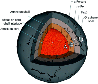
A molecular cracking and welding (MCW) method is proposed to produce multi-layer graphene materials from biomass feedstocks. First, graphene-encapsulated core–shell nanoparticles are formed by catalytic thermal decomposition of solid carbon resources, followed by cracking and paring of graphene shells from metal cores. After graphene shells are peeled off, the cracked graphene shells are simultaneously welded and reconstructed to form multilayer graphene materials under a selected gas atmosphere. The graphene shells will be joined through the unsaturated bonds of the carbon atoms on the edges or linked by carbon atoms from decomposition of welding molecules or just agglomerate through van der Waals forces.Fig. 1 illustrates the concept of this process. This molecular cracking and welding (MCW) technique is a single step process with two stages, i.e., in the first stage, carbon-encapsulated transition metal nanostructures are prepared. Then in the second stage these carbon-encapsulated transition metal structures are opened by using ‘cracking gas agents’ such as H2, H2O, CO2, and CH4 (Fig. 2a), and the graphene shells are peeled off the iron core; the cracked carbon shells are simultaneously welded or reconstructed to form multilayer graphene materials at high temperature with selected welding reagent gases such as light hydrocarbons (methane, ethane, propane, natural gas, etc.) and hydrogen (Fig. 2b).
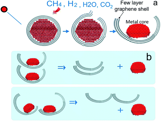 | ||
| Fig. 2 Scheme of cracking a carbon-encapsulated core–shell nanoparticle (a) and scheme of peeling and reconstruction of the cracked graphene shells (b). | ||
3. Experimental
3.1 Precursor preparation
Any carbon-containing source can be used for the production of carbon-encapsulated core–shell nanoparticles.31 Kraft lignin was used as the carbon precursor in this work. 300 grams of kraft lignin was first added to 300 mL tetrahydrofuran in a 2000 mL glass beaker and the lignin–tetrahydrofuran mixture was stirred for 2 hours. 246.0 grams of iron(III) nitrate nonahydrate was added to 100 mL DI water in a 500 mL glass beaker and the iron nitrate–water mixture was stirred until iron nitrate was dissolved completely. The iron nitrate solution (∼2 mL min−1) was added dropwise to the lignin–tetrahydrofuran mixture. The final mixture was stirred for 2 hours, followed by keeping it at room temperature for 24 h and oven-drying at 110 °C for one day.3.2 Pretreatment of precursors
One hundred fifty grams (150 g) of the dried iron–lignin sample from the previous step was thermally treated using a muffle furnace. The inert carrier gas – either argon or nitrogen – was first introduced into the furnace at a flow rate of 80 mL min−1 for 30 minutes. The furnace was temperature-programmed with a rate of 2.5 °C min−1 to 300 °C and kept at 300 °C for 2 hours. The furnace was turned off and the samples could cool to ambient temperature naturally. Then the cooled sample was loaded into a ball mill machine and ground in 1000 rpm for 30 minutes.3.3 Production of graphene nanomaterials by the molecular cracking and welding (MCW) process
Fifty grams (50 g) of Fe–lignin sample were packed in the middle of a 2-inch OD ceramic tubular reactor in each run. The welding gas was introduced into the reactor. The reactor was temperature-programmed with a heating rate of 10 °C min−1 to 1000 °C and kept at 1000 °C for 0, 0.5, 1, 3, or 5 hours. The furnace was cooled down at 10 °C min−1 to room temperature.The conventional acid treatment has been used to purify graphene products. Before the acid treatment, the raw graphene products were treated in the tubular reactor with a carbon dioxide flow (500 mL min−1) at 700 °C for 6 hours. For the acid treatment, the CO2 treated graphene product was first distributed into concentrated (36%) HCl in a flask; the mixture was then sonicated for 6 h, and the sample was refluxed at temperatures between 85 and 90 °C for 6 h. After each treatment, the liquids were kept overnight in their flasks, and then were filtered to collect the solid graphene powder. After HCl acid treatment, the solid graphene powder was further treated with 5 M HNO3 at temperatures between 45 and 50 °C for 6 h and filtered; the filtered acidic liquid was collected and the solid was washed with deionized water until neutral pH. The solid was dried in a vacuum oven at a temperature of 100 °C for 12 h to remove eventual moisture.
To estimate the purity of the graphene after the acid treatments, TGA was performed using a Shimadzu TGA-50H instrument. The analyses of the raw and purified graphene products were carried out under an air flow, which means that a temperature-programmed oxidation (TPO) has been investigated for the graphene products; graphene and amorphous carbon are burnt during the TPO process, and the residue at the end of TPO is iron oxide. During this test of TGA, the variables used were: a range of temperature from 50 to 800 °C and a heating rate of 5 °C min−1 in a 20 mL min−1 air flow. The typical TGA results of the raw graphene and the purified graphene samples are plotted in Fig. S1;† TGA results demonstrate that there is 23–25% metal in the raw graphene materials, and the purity of the final graphene products in this work is between 92% and 96%. Beside the graphene structures, there are 3–5% amorphous carbon and 0.3–3% catalyst metals.
4. Results and discussion
4.1 Formation of graphene encapsulated core–shell nanoparticles
Based on the MCW concept, graphene-encapsulated core–shell nanoparticles are first prepared by catalytic thermal decomposition of solid biomass. Highly stable carbon-encapsulated metal nanoparticles are produced by thermal decomposition of Fe–lignin precursors at high temperature. Multi-layer graphene-encapsulated iron nanoparticles (MGEINs) were observed embedding in macro-porous carbon frames; the pore sizes in the carbon frames vary from 0.1 μm to 10 μm and the wall thickness ranges from 0.05 to 0.5 μm.27,38 Two types of graphene-encapsulated iron nanoparticles are formed,27,38i.e., the majority of the nanoparticles (>90%) are embedded in the wall with a narrow particle size of less than 10 nm (Fig. 3a and c) and large size particles are distributed over the wall surface with diameters ranging from 10 to 100 nm (Fig. 3b and d). Most of these carbon encapsulated nanoparticles have core diameters of 3–8 nm (Fig. 3a and c) and the carbon shell is composed of 2–5 layers of graphene structures (Fig. 3c). The nanoparticle model was proposed in previous studies.27–31 In this model, a graphene-encapsulated metal nanoparticle consists of four concentric layers: an α-iron core, with a γ-iron layer, a carbide interface layer and an outer graphene shell.27–31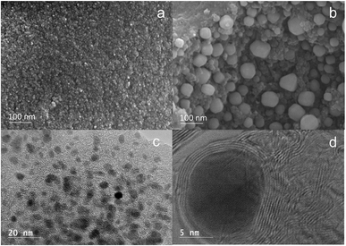 | ||
| Fig. 3 SEM (a and b) and HRTEM (c and d) images of catalytic thermal decomposition of iron–lignin precursors at 1000 °C under an argon atmosphere. | ||
4.2 Cracking the core–shell structures by selected gases and the formation of graphene shell units
To produce graphene materials, one of the straightforward strategies is to peel the graphene shells from the metal cores, and then use these cracked graphene shells as building blocks to make different graphene-based materials. As shown in Fig. 4, there are three different possible ways to separate the graphene shell from its metal core: (i) cracking the graphene shell, (ii) attacking the interface layer between the graphene shell and an inner core and (iii) attacking the entire metal core.Regarding the graphene-encapsulated iron nanoparticle in Fig. 4 and the different graphene shell separation mechanisms, the graphene (Cg) outer shell of the graphene-encapsulated iron nanoparticle may be cracked by reactive molecules such as H2, CO2 and H2O through the following reactions at high temperature:
| Cg + 2H2 → CH4 | (R1) |
| Cg + H2O → CO + H2 | (R2) |
| Cg + CO2 → 2CO | (R3) |
However, the graphene shell will also be etched by hydrogen, steam, and carbon dioxide at high temperature in this process which greatly decreases the quality and the yield of the graphene-based products.27,29
Alternatively, the Fe3C interface layer and the γ-iron sub-layer may be decarburized. At certain temperature and cracking/welding gas partial pressure, gas molecules may permeate through the graphene shell and react with iron carbide (Fe3C) and γ-iron. Specifically, under a hydrogen atmosphere, hydrogen atoms diffuse into and react with cementite and carbon in γ-iron through the following reactions:21,29
| Fe3C + 2H2 → 3Fe + CH4 | (R4) |
| C(γ-iron) + 2H2 → CH4 | (R5) |
The activity of carbon in Fe3C is much higher than that in iron phases. Thus, hydrogen will react more rapidly with carbon in Fe3C than with the carbon dissolved in γ-Fe.21,27 Therefore, the decarburization rate will be greater for cementite as compared to α-Fe and γ-Fe. Thus, Fe3C at the interface will be first and quickly decarburized by hydrogen to an iron phase and the carbon will be released as methane (CH4).
Under a CO2 atmosphere, cementite and carbon in γ-iron as well as Fe are oxidized to Fe3O4 and CO:
| CO2 + Fe3C → Fe3O4 + CO | (R6) |
| CO2 + Fe → Fe3O4 + CO | (R7) |
| C(γ-iron) + CO2 → 2CO | (R8) |
CO2 is a strong oxidant at high temperature; graphene-encapsulated iron nanostructures will be destroyed, and the graphene shell can be cracked and peeled off from the iron core; however, the strong etching effect on the graphene shell makes CO2 not a suitable cracking and welding gas.
There are a few reactions occurring under a methane atmosphere: CH4 is catalytically decomposed to graphene and H2 over an iron particle surface, methane can also react with iron to form Fe3C, and part of the carbon atoms from methane will diffuse into γ- and α-iron phases:
| CH4 → C(graphene) + 2H2 | (R9) |
| 3Fe(γ-iron) + CH4 → Fe3C + 2H2 | (R10) |
| CH4 → C(γ-iron) + 2H2 | (R11) |
| CH4 → C(α-iron) + 2H2 | (R12) |
With more carbon deposited between the graphene shell and iron core, the iron core will expand in volume, facilitating the cracking of the graphene shell.
Fig. 5 displays HRTEM images of the Fe–kraft lignin samples after catalytic thermal treatment under different atmospheres. Small and uniformly distributed iron particles were observed in the sample produced under argon (Fig. 5a). The HRTEM images of the sample showed that the nanoparticles in the sample have a core–shell structure with the diameter of the core nanospheres approximately 3–5 nm. The carbon shells exhibiting ordered planes of the graphene structure were observed with 2–10 layers (Fig. 5a). Fig. 5b shows the HRTEM image of a thermally treated Fe–kraft lignin sample under H2. Core–shell nanoparticles were etched in the sample (Fig. 5b). Nano-iron particles were trapped loosely in the etched graphene shells (Fig. 5b). The HRTEM image of the sample produced under a CO2 atmosphere is shown in Fig. 5c. Graphene-encapsulated iron nanostructures were destroyed due to the etching effects of CO2 at high temperature. Sphere- or rectangle-shaped Fe3O4 nanoparticles were observed in this sample;27,28 these particles were usually encapsulated in 1 to 2 layers of etched graphene (Fig. 5c). Fig. 5d shows the HRTEM images of the Fe–lignin sample carbonized at 1000 °C under a methane atmosphere. The graphene shell was peeled off the iron core (Fig. 5d).
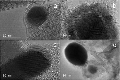 | ||
| Fig. 5 HRTEM images of catalytically cracked graphene-encapsulated metal nanoparticles at 1000 °C under different atmospheres: Ar (a), H2 (b), CO2 (c), and CH4 (d). | ||
Thus, for graphene-encapsulated iron particles, hydrogen and carbon dioxide are more destructive and have strong etching effects on graphene structures. However, methane may crack the graphene shell without significant etching. Similarly, natural gas (NG) is a suitable cracking/welding gas as NG is composed of ∼95% methane by volume. It is noted that cracking/welding gases which are less suitable for graphene-encapsulated iron nanoparticles may be acceptable for other types of graphene-encapsulated metal nanoparticles.
4.3 Formation of graphene materials from cracked graphene shells
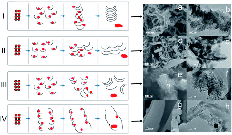
It is found that the cracking/welding gas composition may be selected to most effectively “peel” off the graphene shell from the metal core, which then may serve as a “building block” to provide various graphene morphologies via “welding” processes. A welding technique has been used for joining/merging nanomaterials like nanoparticles,32 nanowires,33 nanotubes,34,35 and nanofibers36 under conditions such as heating and irradiation. These physical welding processes can mainly produce nano-structured materials with a low yield and selectivity.27The graphene-based material formed via the present methods comprises graphene shells (single layer and/or multilayer graphene). The graphene may adopt a variety of morphologies including, flat graphene sheets, curved graphene sheets, graphene chains, graphene sponges, fluffy graphene, graphene strips with a common metal joint, and graphene nanoplatelets. Fig. 6 illustrates some of the different graphene morphologies which may be formed. In the schematic panels, the filled circles represent metal cores and the thin curves represent graphene shells. The schematic panels further illustrate the MCW described above, involving cracking of the graphene shells and reconstruction of graphene shells to form different graphene morphologies. The SEM and TEM images on the right correspond to graphene-based materials formed using the present methods. The top row (I) illustrates the formation of graphene chains. The next row down (II) illustrates the formation of graphene nanoplatelets. The next row down (III) illustrates the formation of fluffy graphene. The last row (IV) illustrates the formation of curved graphene sheets. The formation of graphene chains (I) generally involves connecting hundreds of graphene shell building blocks along the perpendicular direction. Each graphene shell building block may be composed of 1 to 30 layers of graphene and may have an average thickness of 10 nm or less. The in-plane dimensions of each graphene shell building block may range from several nm to 20 nm. The length of the graphene chains may vary from hundreds of nanometers to over 10 μm. The formation of graphene nanoplatelets (II) generally involves bonding along the horizontal direction of graphene shell building blocks. Otherwise the dimensions of the graphene shell building blocks may be as described above with respect to the graphene chains (I). The formation of fluffy graphene (III) generally involves random bonding along various directions. Otherwise the dimensions of the graphene shell building blocks may be as described above with respect to the graphene chains (I). The formation of curved graphene sheets generally involves reconstruction in both the horizontal and the perpendicular directions. Otherwise the dimensions of the graphene shell building blocks may be as described above with respect to the graphene chains (I).
In addition to the type of cracking and welding gas composition, the conditions under which the graphene-encapsulated metal nanoparticles are exposed to the gas composition include the flow rate of the gas(es), the temperature (Fig. S2–S4†), the heating rate to achieve the selected temperature, the heating time (Fig. S5–S7†) and the particle size (Fig. S8 and S9†) (i.e., the particle size of the graphene-encapsulated metal nanoparticles in the carbon matrix). These parameters may be selected to achieve a desired morphology and yield of the graphene-based material (Fig. S10†). The selection of these parameters may depend upon the type of graphene-encapsulated metal nanoparticle (e.g., the type of metal) used. The ideal welding temperature was found to be at least 1000 °C, with the heating time ranging from 0.5 to 1 hour. The selected welding gases were methane (CH4) and natural gas (NG). The optimized Fe–lignin precursor particle size was examined between 125 and 250 microns (μm).
5. Crude oil/water emulsion separation system
In the past decade, extensive studies developed bio-aerogels and related bio-material absorbents for oil spilling cleanup.37–39 These materials can be used to absorb oil including gasoline, diesel oil, olive oil, benzene, phenixin, isopropanol, etc.40 Crude oil with very high viscosity is the most difficult oil for these absorbents with low absorption capacity,39 especially, the crude oil/water emulsion. Since the dispersive water molecules in the emulsion wrapped the lipophilic groups of the absorbents which resulted in loss of bonding between oil molecules and lipophilic group of the absorbents, the crude oil/water emulsion cannot be separated by these existing bio-absorbents. In this study, a novel multilayer graphene material with super hydrophobic properties and a large surface area has been developed. In addition, an application for this material has been identified for separating water from a crude oil emulsion in our research for the petroleum industry. Fig. 7 shows the process to separate crude oil and water emulsions.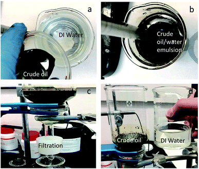 | ||
| Fig. 7 Separation system and process for a crude oil/water emulsion. (a) DI water and crude oil; (b) crude oil/water emulsion; (c) filtration; (d) separation. | ||
In the experimental part, a 100 mL crude oil/100 mL water mixture was emulsified by using a high speed mechanical mixer (Fig. 7a and b); a 10 g bio-graphene material was uniformly loaded on the filter sieve in the filtration system before the crude oil/water emulsion was poured into the filter beaker, and then the crude oil/water emulsion was successfully separated using this material as a filter (see Video S1†). The results showed that more than 3000% crude oil/water emulsion by weight can be separated by this bio-graphene material. Moreover, this bio-graphene material can be recycled through removing the purified crude oil under vacuum system and reused for this separation system. This separation system and process can be used to remove water from crude oil emulsions in the petroleum industry.
6. Conclusions
A novel method is developed for high-volume production of low-cost graphene materials from any solid carbon-containing source. Multi-layer nano-shell structure-based graphene materials from solid carbon resources are produced through a molecular cracking and welding (MCW) method. In the MCW process, multi-layer graphene-encapsulated core–shell nanoparticles were first formed by catalytic thermal decomposition of transition metal-promoted solid carbon resources, and then in the second stage, these graphene-encapsulated core–shell structures were cracked and graphene shells were peeled off the metal cores, and these graphene shell units were welded and reconstructed to form different multilayer graphene-based materials (fluffy, chain, multi-layer graphene nanoplatelets, flat or curved sheet-like) under high temperature with selected welding reagent gases. The selected cracking-welding gases were methane (CH4), hydrogen (H2), carbon dioxide (CO2) and natural gas (NG). These bio-based graphene materials are successfully used to separate water from crude oil emulsions in the petroleum industry.Conflicts of interest
There are no conflicts to declare.References
- G. Lalwani, A. M. Henslee, B. Farshid, L. Lin, F. K. Kasper, Y.-X. Qin, A. G. Mikos and B. Sitharaman, Two-Dimensional Nanostructure-Reinforced Biodegradable Polymeric Nanocomposites for Bone Tissue Engineering, Biomacromolecules, 2013, 14, 900–909, DOI:10.1021/bm301995s.
- R. Tkacz, R. Oldenbourg, S. B. Mehta, M. Miansari, A. Verma and M. Majumder, pH dependent isotropic to nematic phase transitions in graphene oxide dispersions reveal droplet liquid crystalline phases, Chem. Commun., 2014, 50, 6668, 10.1039/c4cc00970c.
- M. Xu, D. Fujita and N. Hanagata, Perspectives and Challenges of Emerging Single-Molecule DNA Sequencing Technologies, Small, 2009, 5, 2638–2649, DOI:10.1002/smll.200900976.
- F. Schedin, A. K. Geim, S. V. Morozov, E. W. Hill, P. Blake, M. I. Katsnelson and K. S. Novoselov, Detection of individual gas molecules adsorbed on graphene, Nat. Mater., 2007, 6, 652–655, DOI:10.1038/nmat1967.
- D. Akinwande, L. Tao, Q. Yu, X. Lou, P. Peng and D. Kuzum, Large-Area Graphene Electrodes: Using CVD to facilitate applications in commercial touchscreens, flexible nanoelectronics, and neural interfaces, IEEE Nanotechnol. Mag., 2015, 9, 6–14, DOI:10.1109/MNANO.2015.2441105.
- H. Fei, R. Ye, G. Ye, Y. Gong, Z. Peng, X. Fan, E. L. G. Samuel, P. M. Ajayan and J. M. Tour, Boron- and Nitrogen-Doped Graphene Quantum Dots/Graphene Hybrid Nanoplatelets as Efficient Electrocatalysts for Oxygen Reduction, ACS Nano, 2014, 8, 10837–10843, DOI:10.1021/nn504637y.
- M. Zhong, D. Xu, X. Yu, K. Huang, X. Liu, Y. Qu, Y. Xu and D. Yang, Interface coupling in graphene/fluorographene heterostructure for high-performance graphene/silicon solar cells, Nano Energy, 2016, 28, 12–18, DOI:10.1016/j.nanoen.2016.08.031.
- M. D. Stoller, S. Park, Y. Zhu, J. An and R. S. Ruoff, Graphene-Based Ultracapacitors, Nano Lett., 2008, 8, 3498–3502, DOI:10.1021/nl802558y.
- F. Yao, F. Güneş, H. Q. Ta, S. M. Lee, S. J. Chae, K. Y. Sheem, C. S. Cojocaru, S. S. Xie and Y. H. Lee, Diffusion Mechanism of Lithium Ion through Basal Plane of Layered Graphene, J. Am. Chem. Soc., 2012, 134, 8646–8654, DOI:10.1021/ja301586m.
- S. Amini, J. Garay, G. Liu, A. A. Balandin and R. Abbaschian, Growth of large-area graphene films from metal-carbon melts, J. Appl. Phys., 2010, 108, 94321, DOI:10.1063/1.3498815.
- G. Eda, G. Fanchini and M. Chhowalla, Large-area ultrathin films of reduced graphene oxide as a transparent and flexible electronic material, Nat. Nanotechnol., 2008, 3, 270–274, DOI:10.1038/nnano.2008.83.
- C. Zhu, T. Y.-J. Han, E. B. Duoss, A. M. Golobic, J. D. Kuntz, C. M. Spadaccini and M. A. Worsley, Highly compressible 3D periodic graphene aerogel microlattices, Nat. Commun., 2015, 6, 6962, DOI:10.1038/ncomms7962.
- W. Gao, M. Majumder, L. B. Alemany, T. N. Narayanan, M. A. Ibarra, B. K. Pradhan and P. M. Ajayan, Engineered Graphite Oxide Materials for Application in Water Purification, ACS Appl. Mater. Interfaces, 2011, 3, 1821–1826, DOI:10.1021/am200300u.
- P. Liu, A. L. Cottrill, D. Kozawa, V. B. Koman, D. Parviz and A. T. Liu, et al., Emerging trends in 2D nanotechnology that are redefining our understanding of “Nanocomposites”, Nano Today, 2018, 21, 18–40 CrossRef CAS.
- H. Khoshnevis, S. M. Mint, E. Yedinak, T. Q. Tran, A. Zadhoush and M. Youssefi, et al., Super high-rate fabrication of high-purity carbon nanotube aerogels from floating catalyst method for oil spill cleaning, Chem. Phys. Lett., 2018, 693, 146–151 CrossRef CAS.
- Growth Opportunities in the Global Composites Industry, ID: 4331665, Report June 2017 Region: Global 383 pages, Lucintel, https://www.researchandmarkets.com/reports/4331665 Search PubMed.
- J. H. Lora, Utilization opportunities for biorefinery lignins: an Industrial perspective, in: Int. Lignin Biochem. Conf., Toronto, Canada, 2010 Search PubMed.
- L. Torres, L. Gomez Armas and A. Carlos Seabra, Optimization of Micromechanical Cleavage Technique of Natural Graphite by Chemical Treatment, Graphene, 2014, 3, 1–5, DOI:10.4236/graphene.2014.31001.
- S. Stankovich, D. A. Dikin, R. D. Piner, K. A. Kohlhaas, A. Kleinhammes, Y. Jia, Y. Wu, S. T. Nguyen and R. S. Ruoff, Synthesis of graphene-based nanosheets via chemical reduction of exfoliated graphite oxide, Carbon, 2007, 45, 1558–1565, DOI:10.1016/j.carbon.2007.02.034.
- E. Rollings, G.-H. Gweon, S. Y. Zhou, B. S. Mun, J. L. McChesney, B. S. Hussain, A. V. Fedorov, P. N. First, W. A. de Heer and A. Lanzara, Synthesis and characterization of atomically thin graphite films on a silicon carbide substrate, J. Phys. Chem. Solids, 2006, 67, 2172–2177, DOI:10.1016/j.jpcs.2006.05.010.
- M. Zheng, K. Takei, B. Hsia, H. Fang, X. Zhang, N. Ferralis, H. Ko, Y.-L. Chueh, Y. Zhang, R. Maboudian and A. Javey, Metal-catalyzed crystallization of amorphous carbon to graphene, Appl. Phys. Lett., 2010, 96, 63110, DOI:10.1063/1.3318263.
- C. Mattevi, H. Kim and M. Chhowalla, A review of chemical vapour deposition of graphene on copper, J. Mater. Chem., 2011, 21, 3324–3334, 10.1039/C0JM02126A.
- Y. Zhang, L. Zhang and C. Zhou, Review of Chemical Vapor Deposition of Graphene and Related Applications, Acc. Chem. Res., 2013, 46, 2329–2339, DOI:10.1021/ar300203n.
- Y. Zhang, L. Gomez, F. N. Ishikawa, A. Madaria, K. Ryu, C. Wang, A. Badmaev and C. Zhou, Comparison of Graphene Growth on Single-Crystalline and Polycrystalline Ni by Chemical Vapor Deposition, J. Phys. Chem. Lett., 2010, 1, 3101–3107, DOI:10.1021/jz1011466.
- H. An, W.-J. Lee and J. Jung, Graphene synthesis on Fe foil using thermal CVD, Curr. Appl. Phys., 2011, 11, S81–S85, DOI:10.1016/j.cap.2011.03.077.
- X. Liu, L. Fu, N. Liu, T. Gao, Y. Zhang, L. Liao and Z. Liu, Segregation growth of graphene on Cu–Ni alloy for precise layer control, J. Phys. Chem. C, 2011, 115, 11976–11982, DOI:10.1021/jp202933u.
- Q. Yan, Catalytic thermal conversion of kraft lignin to multi-layer graphene materials, Doctoral dissertation, 2017, retrieved from https://search.proquest.com/docview/1889555601?pq-origsite=gscholar.
- Q. Yan, J. Li, X. Zhang, J. Zhang and Z. Cai, In situ formation of graphene-encapsulated iron nanoparticles in carbon frames through catalytic graphitization of kraft lignin, Nanomater. Nanotechnol., 2018, 184798041881895 CrossRef.
- Q. Yan, X. Zhang, J. Li, C. Wang, J. Zhang and Z. Cai, Catalytic conversion of Kraft lignin to bio-multilayer graphene materials under different atmospheres, J. Mater. Sci., 2018, 53(11), 8020–8029 CrossRef CAS.
- Q. Yan, C. Wan, J. Liu, J. Gao, F. Yu, J. Zhang and Z. Cai, Iron nanoparticles in situ encapsulated in biochar-based carbon as an effective catalyst for the conversion of biomass-derived syngas to liquid hydrocarbons, Green Chem., 2013, 15(6), 1631–1640 RSC.
- Z. Cai, Q. Yan, J. Li, J. Zhang, B. Marcoccia and J. Freiberg, Methods for synthesizing graphene from encapsulated particles, US Pat., Pub. No. 20180194630, 2018.
- M. N. Ding, D. C. Sorescu, G. P. Kotchey and A. Star, Welding of Gold Nanoparticles on Graphitic Templates for Chemical Sensing, J. Am. Chem. Soc., 2012, 134, 3472–3479 CrossRef CAS PubMed.
- Y. Lu, J. Y. Huang, C. Wang, S. H. Sun and J. Lou, Cold welding of ultrathin gold nanowires, Nat. Nanotechnol., 2010, 5, 218–224 CrossRef CAS.
- A. R. Harutyunyan, Welding of carbon single-walled nanotubes by microwave treatment, US Pat., 7611687 B1, 2010.
- Z. Lin, X. Gui, Q. Gan, W. Chen, X. Cheng, M. Liu, Y. Zhu, Y. Yang, A. Cao and Z. Tang, In Situ Welding Carbon Nanotubes into a Porous Solid with Super-High Compressive Strength and Fatigue Resistance, Sci. Rep., 2015, 5, 11336 CrossRef CAS PubMed.
- J. Cao, et al., Programmable Writing of Graphene Oxide/Reduced Graphene Oxide Fibers for Sensible Networks with In Situ Welded Junctions, ACS Nano, 2014, 8, 4325–4333 CrossRef CAS PubMed.
- M. O. Adebajo, R. L. Frost, J. T. Kloprogge, O. Carmody and S. Kokot, Porous materials for oil spill cleanup: a review of synthesis and absorbing properties, J. Porous Mater., 2003, 10(3), 159–170 CrossRef CAS.
- Q. Zheng, Z. Cai and S. Gong, Green synthesis of polyvinyl alcohol (PVA)–cellulose nanofibril (CNF) hybrid aerogels and their use as superabsorbents, J. Mater. Chem. A, 2014, 2(9), 3110–3118 RSC.
- T. Zhai, Q. Zheng, Z. Cai, L.-S. Turng, H. Xia and S. Gong, Poly(vinyl alcohol)/cellulose nanofibril hybrid aerogels with an aligned microtubular porous structure and their composites with polydimethylsiloxane, ACS Appl. Mater. Interfaces, 2015, 7(13), 7436–7444 CrossRef CAS PubMed.
- R. Wahi, L. A. Chuah, T. S. Y. Choong, Z. Ngaini and M. M. Nourouzi, Oil removal from aqueous state by natural fibrous sorbent: an overview, Sep. Purif. Technol., 2013, 113, 51–63 CrossRef CAS.
Footnote |
| † Electronic supplementary information (ESI) available. See DOI: 10.1039/c9ta01332f |
| This journal is © The Royal Society of Chemistry 2019 |


