 Open Access Article
Creative Commons Attribution 3.0 Unported Licence
A review of nanostructured non-titania photocatalysts and hole scavenging agents for CO2 photoreduction processes
Jeannie Z. Y.
Tan
 * and
M. Mercedes
Maroto-Valer
Research Centre for Carbon Solutions (RCCS), Heriot-Watt University, Edinburgh EH14 4AS, UK. E-mail: j.tan@hw.ac.uk
First published on 1st April 2019
Abstract
The imperative for the development of sustainable energy technologies to alleviate the heavy reliance on fossil fuels as well as to mitigate the serious environmental issues associated with CO2 emission has fostered the development of solar fuels through CO2 photoreduction. The well-documented TiO2 and modified TiO2-based photocatalysts have been shown to photoreduce CO2 into hydrocarbons. Meanwhile, there is also an increasing interest in the utilisation of non-titania based materials, namely metal sulphides, oxides, oxynitrides and nitrides, for CO2 photoreduction. Distinct from other published reviews, we discuss here recent progress made in designing metal sulphide, oxide, oxynitride and nitride photocatalysts for CO2 photoreduction through morphological changes, aiming at providing a systematic summary of non-titania based materials for CO2 photoreduction. Furthermore, the introduction of hole scavengers in order to maximise the CO2 photoreduction efficiency is also reviewed.
1. Introduction
Fossil fuels are currently unrivalled for energy generation, and our existing infrastructure is built to handle fossil fuels for transportation, heating and electricity.1 Our heavy reliance on fossil fuels results in annual emissions of 32 Gt of CO2.2 This is likely to increase to 36–43 Gt by 2035, subject to policies governing CO2 emissions and energy use, even with increasing renewable energy sources.3 To mitigate these environmental issues as well as alleviate our dependence on fossil fuels, harvesting the seemingly infinite solar energy and storing it in the form of chemical fuels hold significant promise to address current and future energy demands. Moreover, the chemical industry and a vast amount of chemical products rely heavily on using fossil fuel feedstock. This further motivates the development of sustainable processes to generate fuels and chemical feedstock from water and CO2 using solar energy. Such a process is akin to photosynthesis in nature, and therefore, it is referred to as the artificial photosynthesis.Photoelectrocatalytic reduction of CO2 in aqueous suspensions using semiconducting powders was first proposed by Inoue et al. in 1979.4 Later in 1987, the photocatalytic reduction of CO2 to CH4 in the presence of H2O was proposed by Thampi et al.5 Since then, an increasing number of studies on the photo(electro)catalytic reduction of CO2 have been conducted (Fig. 1). Among these studies, almost 50% focused on the materials employed as photocatalysts for conversion of CO2 under UV and/or visible irradiation. The rest of the studies concentrated mainly on modelling or process development. The use of TiO2 as a photocatalyst for CO2 reduction has been extensively studied and has been reviewed elsewhere.6–10 However, the lack of systematic studies of non-TiO2 semiconducting materials, namely metal sulphides, oxides, oxynitrides and nitrides, for CO2 photoreduction (CO2PR) has inhibited the development of these photocatalysts compared to titania-based photocatalysts.
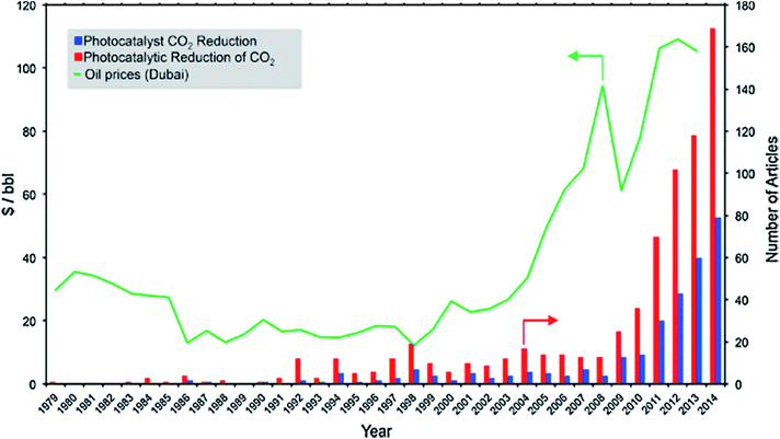 | ||
| Fig. 1 Timeline for the number of articles published on CO2 photoreduction vs. the price of oil. Reproduced from ref. 11 with permission. | ||
Although different photocatalysts (i.e., titania and non-titania based semiconductors) have been proposed in the literature, the overall CO2PR conversion remains low especially under sunlight irradiation, making the CO2PR system not practical for commercialisation. To further increase the efficiency of CO2PR, the introduction of scavenging agents into the CO2PR system has been proposed. However, so far, the introduction of hole scavenging agents has not been systematically studied, though studies started in the last century. Therefore, the necessity to systematically scrutinise the recent development of non-TiO2 photocatalysts and hole scavenging agents for CO2PR is of great demand.
There are enormous scientific and technical challenges involved in making even the simplest fuel, H2, and even more so for carbon-based fuels by means of CO2 photoreduction. Similar to other photocatalytic processes, solar-driven photocatalytic conversion of CO2 in the presence of H2O to hydrocarbon fuels uses semiconducting materials to harvest solar energy and provides active sites to allow the photocatalytic conversion process to occur. The basic steps of the photocatalytic process can be summarised as follows:
(1) generation of charge carriers (electron–hole pairs) by semiconducting materials upon absorption of photons with appropriate energy from the irradiation of light,
(2) separation of charge carriers and their transportation to the surface of the photocatalyst, and
(3) chemical redox reactions between the charge carriers and the reactants.
CO2PR with H2O into fuels is illustrated in Fig. 2. TiO2 was the first material used for CO2PR,5 and since then it has been widely used because of its abundance, availability, high chemical stability, low cost and non-toxicity.12 Despite the great effort made in the CO2PR using TiO2 and its derivative materials, the efficiency of the process remains low,7 mainly attributed to the following factors:
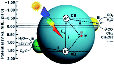 | ||
| Fig. 2 Schematic illustration of photocatalytic CO2 reduction with H2O over a heterogeneous photocatalyst. The dotted lines indicate the thermodynamic potentials for water oxidation and CO2 reduction into CO, CH3OH and CH4. Reproduced from ref. 26 with permission. | ||
(a) Rapid recombination of photogenerated electron–hole pairs;10
(b) Mild reducing power;
• The potential of the conduction band electrons is only slightly more negative than the multi-electron reduction potentials of CO2, thus providing a very small driving force, whereas the potential of the valence band holes is much more positive than the water oxidation potential.7
(c) Limited visible light absorption due to the wide bandgap (3.0–3.2 eV) of TiO2.13,14
Strategies including doping,15,16 coupling with semiconductors,17–19 dye sensitizing,20,21 surface modification22,23etc. have been extensively used to improve TiO2 photocatalysts and are summarised elsewhere.9,14,24,25 However, the two most commonly used methods for extending the absorption range to visible light, namely sensitization or doping, do not fully address the optical issue of wide bandgap materials. Sensitizing agents (e.g., dyes or quantum dots) often degrade when exposed to UV light and photogenerate oxidizing holes in TiO2.7 Dopant atoms, on the other hand, can become the centers of charge recombination. Moreover, the additional energy states associated with foreign atoms are highly localized, resulting in suppressed charge mobility.27 Hence, while TiO2 remains a benchmark photocatalyst, there is a lot of interest in developing other materials for CO2PR, such as carbon-based semiconductors (e.g., graphene-based composites,28,29 carbon nanotube composites,30 g-C3N4 based composites31–33 and hybrid organic–inorganic materials34–37) and other inorganic transition or main group metal oxides, sulphides, oxynitrides, and nitrides. Since the use of carbon-based semiconductors for CO2PR has been reviewed elsewhere,30,34,38,39 these photocatalysts are not be discussed herein.
Inorganic semiconductors, namely metal oxides, sulphides, oxynitrides and nitrides, are among the first semiconductors used for solar-driven reactions. They possess relatively high stability, are low cost and absorb light consisting of photons with energy equal to or greater than their bandgap.40 This very diverse group of materials includes both narrow and wide bandgap semiconductors; yet many of them offer a more favourable bandgap than TiO2. Moreover, many recent CO2PR developments follow similar trends to those for photocatalytic water splitting, as both processes share similar constraints on energy bands.41–43 Specifically, the quest for new semiconductor materials is focused on the following points:27
(a) rising the valence band energy to decrease the bandgap,
(b) moving the conduction band to more reductive potentials,
(c) improving the quantum efficiency of exciton formation whilst suppressing charge recombination and
(d) using novel nanoscale morphologies to provide a large surface area with multiple photocatalytically active sites.
To achieve the quest mentioned above, different methods have been proposed previously and are reviewed in the following sections.
2. Non-TiO2 materials for CO2 photoreduction reactions
Although the position of conduction and valence bands is important for photocatalytic properties, the morphology of materials plays a critical role. Furthermore, manipulating the microstructure has also shown to alter the bandgap energy,44 suppress the charge recombination,45 enhance the diffusion of electrons towards the surface of photocatalysts,46 induce quantum confinement effects47 and provide more photocatalytic active sites, thereby enhancing the photocatalytic performance. In this section, nanostructured non-TiO2 semiconducting materials for CO2PR published in the last two decades are reviewed, including metal sulphides, oxides, oxynitrides and nitrides.2.1 Sulphides
Sulphide semiconductors received a lot of attention for CO2PR. This was because their valence band, made of 3p orbitals of the sulphur atoms, is located higher than those of their oxide analogues, resulting in the conduction band being more reductive.42 Many sulphides have a narrow bandgap (e.g., PbS and Bi2S3), with the absorption onset in the visible and infrared regions. Amongst sulphide semiconductors, ZnS and CdS were the most studied sulphides for CO2PR. ZnS is a wide bandgap semiconductor (Eg = 3.66 eV in the bulk); however, it possesses a strong reducing power of the conduction band (ECB = −1.85 V vs. the NHE at pH 7).48| No. | Photocatalyst | Product(s) of CO2 photoreduction (μmol gcatalyst−1 h−1) | Light source | Ref. |
|---|---|---|---|---|
| Sulphides | ||||
| 1. | ZnS/montmorillonite nanocomposite | CH4 1.17 | UV 8 W Hg lamp (λ = 254 nm) | 49 |
| CO 0.125 | ||||
| 2. | CdS wurtzite/zinc-blende nanohybrid | CO 1.61 | 300 W Xe lamp (λ ≥ 420 nm) | 54 |
| CH4 0.31 | ||||
| 3. | Bi2S3/CdS | CH3OH 6.13 mmol gcatalyst−1 h−1 | 500 W Xe lamp (λ ≥ 320 nm) | 59 |
| CdS wurtzite/zinc-blende nanohybrid | CO 1.61 | 300 W Xe lamp (λ ≥ 420 nm) | 54 | |
| CH4 0.31 | ||||
| 4. | ZnxCd1−xS solid solution and tetra(4-carboxyphenyl)porphyrin iron(III) chloride | CO 1.28 μmol | 300 W Xe lamp (420 nm < λ <780 nm | 58 |
| 5. | Cu2S/CuS | CH4 46.21 ± 6.50 μmol m−2 h−1 | A.M 1.5 simulated sunlight | 60 |
| 6. | RuO2-modified CuxAgyInzZnkSm solid solutions | CH3OH 118.5 | 1000 W Xe lamp (λ > 400 nm) | 69 |
![[thin space (1/6-em)]](https://www.rsc.org/images/entities/char_2009.gif) |
||||
| Oxides | ||||
| 7. | ZnO | CH3OH 325 | 355 nm laser beam | 74 |
| 8. | NiO | CH3OH 388 | ||
| 9. | Fluffy mesoporous ZnO | CO 0.73 | 8 W fluorescent tube (7 mW cm−2) | 75 |
| 10. | N-doped ZnO | CO 0.04 | ||
| 11. | ZnO plates | CO 763.5 ppm gcatalyst−1 h−1 | 300 W Xe arc lamp | 76 |
| CH4 205.2 ppm gcatalyst−1 h−1 | ||||
| 12. | Ultralong and ultrathin single crystal Zn2GeO4 nanoribbons | CH4 25 | 300 W Xe arc lamp | 77 |
| 13. | Zn2GeO4 nanorods | CO 179 ppm gcatalyst−1 h−1 | 300 W Xe arc lamp | 78 |
| CH4 35 ppm gcatalyst−1 h−1 | ||||
| 14. | RuO2 and Pt co-loaded Zn1.7GeN1.8O nano-sheaves | ∼55 | 300 W Xe arc lamp (λ > 420 nm) | 79 |
| 15. | ZnGa2O nanosheet-scaffolded microspheres | 69 | 300 W Xe arc lamp with an IR cut filter | 80 |
| 16. | Zn2SnO4 hexagonal nanoplates | 47 | 300 W Xe arc lamp | 81 |
| 17. | Ce-doped ZnFe2O4 | CO ∼20 | Visible light | 82 |
| 18. | Quasi-cubic WO3 | ∼0.34 | 300 W Xe lamp | 83 |
| 19. | Ultrathin single crystal WO3 | ∼1.1 | 300 W Xe arc lamp | 84 |
| 20. | Ultrathin W18O49 | CH4 2200 | Full-arc Xe lamp | 85 |
| 21. | Bi2WO6 nanosheets with well-defined {001} facets | 1.1 | 300 W Xe arc lamp | 86 |
| 22. | BiWO6 | CH3OH 32.6 | 300 W Xe lamp (λ > 420 nm) | 87 |
| 23. | NaNbO3 nanowires | CH4 653 ppm gcatalyst−1 h−1 | 300 W Xe lamp | 88 |
| 24. | KNb3O8 nanobelts | CO 3.58 | 350 W Xe lamp | 89 |
| 25. | HNb3O8 nanobelts | CO 1.71 | ||
| 26. | SrNb2O6 nanorods | CO 51.2 | 400 W Hg lamp | 90 |
| 27. | 3% NiOx–Ta2O5-1% immobilised on reduced graphene | CH3OH 197.92 | 400 W metal halide lamp | 91 |
| 28. | Core–shell Ni/NiO-loaded N-InTaO4 | CH3OH 160 | Xe lamp (100 mW, 390 ≤ λ ≤ 770 | 92 |
| 29. | LaTa7O19 | CO 50 | 400 W Hg lamp | 93 |
| 30. | CaTa4O11 | CO 70 | ||
| 31. | 1.0 wt% Ag-modified Ba-doped NaTaO3 | CO ∼50 | 400 W Hg lamp | 94 |
| 32. | K2YTa5O15 | CO 91.9 | 4000 W Hg lamp | 95 |
| 33. | Ag-modified Ga2O3 | CO 10.5 | UV light | 96 |
| 34. | Lamellar BiVO4 | CH3OH 5.52 | 300 W Xe lamp (full spectrum) | 97 |
| 35. | CuGa1−xFexO | CO ∼9.2 | 300 W Xe arc lamp | 98 |
| 36. | CoAl-layered double hydroxides | CH4 4.2 | 500 W Xe lamp | 99 |
![[thin space (1/6-em)]](https://www.rsc.org/images/entities/char_2009.gif) |
||||
| Oxynitrides | ||||
| 37. | Porous TaON | CH3CHO 0.52 | 300 W Xe lamp | 100 |
| C2H5OH 2.03 | ||||
| 38. | ZnAl2O4-modified ZnGa2ON | CH4 9.2 | 300 W Xe lamp (λ ≥ 420 nm) | 101 |
![[thin space (1/6-em)]](https://www.rsc.org/images/entities/char_2009.gif) |
||||
| Nitrides | ||||
| 39. | GaN | CO 1130 | 300 W Xe lamp | 102 |
| CH4 1.3 | ||||
| 40. | Rh/Cr2O3-decorated GaN nanowires | CO 120 | ||
| CH4 3.5 | ||||
Meng et al. proposed the co-doping of Cd and Cu into ZnS as one of the most active and optimised design routes for metal sulphide photocatalysts so far.52 It was found that the doping of Cu could promote the formation of S vacancies and narrow the bandgap energy of ZnS, whereas surface modification of Cu-doped ZnS with Cd2+ enhanced the product selectivity towards HCOOH (99%) under solar light irradiation. Recently, solid solutions of ZnLn2S4 with a flower-like microstructure decorated with a cubic CeO2 co-catalyst have been shown to exhibit enhanced CH3OH production (0.542 μmol gcatalyst−1 h−1) when compared to pristine CeO2 and ZnLn2S4 (0.139 and 0.073 μmol gcatalyst−1 h−1, respectively) under visible light irradiation (λ ≥ 420 nm).53
The conduction band of CdS is less reductive (ECB = −0.9 V at pH 7 vs. NHE) than that of ZnS. Therefore, CdS is always decorated with noble metals, such as Ag. For instance, Zhu et al. proposed that the loaded Ag could act as an electron trap as well as an active site for CO2PR on CdS.55 The photoproduction of CO was improved by three times when compared with that obtained with bare CdS. Alternatively, CdS can be supported with other wide bandgap semiconductors to enhance its reducing power for CO2PR. Kisch et al. found that the coupling of CdS with ZnS strongly enhanced the CO2PR activity when compared to SiO2-supported CdS or ZnS samples because CdS and ZnS can absorb light at ≤530 nm and ≤330 nm, respectively.56 The study reported that 5 wt% CdS loaded onto ZnS induced a 40-fold and 16-fold enhancement in the production of HCOOH (∼80 mM, λ ≥ 320 nm, 3 h) when compared to unmodified CdS and ZnS, respectively. This strong enhancement was attributed to the electronic semiconductor–support interaction effect that improved the charge separation efficiency of the coupled semiconductor system. A similar observation was also reported by Kočí et al. recently, in which core–shell CdS/ZnS nanoparticles deposited on montmorillonite prepared by a one-pot synthesis exhibited enhanced CO2PR activity in water under UV irradiation (λ = 365 nm).57 The increase in the yield was due to the enhanced charge separation of CdS cores by ZnS shells, the increase of surface area and the inhibition of CdS photocorrosion. CO2PR performed with CdS coupled with Bi2S3, having smaller bandgap energy than CdS, was also reported.59 The Bi2S3/CdS nanocomposite fabricated with 15 wt% Bi2S3 exhibited the highest methanol production from CO2 (6.13 mmol g−1 h−1, Table 1 entry 3), which was at least 50% higher than those obtained with bare Bi2S3 (3.14 mmol g−1 h−1) and CdS (2.01 mmol g−1 h−1), under visible light irradiation. The enhanced photocatalytic activity suggested that the establishment of a heterojunction between CdS and Bi2S3 could improve charge separation and subsequently prolong the lifetime of photogenerated electron–hole pairs. Moreover, the surface area of the Bi2S3/CdS nanocomposite, which was 24–27 m2 g−1, was slightly higher than those of the bare CdS and Bi2S3 (12 and 21 m2 g−1, respectively). Hence, the synergetic effect of surface area and the heterojunction established between these two semiconductors had significantly improved the overall performance in CO2PR. Increasing the specific surface area does not only provide more active sites for the photocatalytic reaction, but also affects the optical properties of the material. For instance, Jin et al. recently proposed that by increasing the length-to-width ratio of Bi2S3 nanoribbons, which increased the bandgap energy of Bi2S3 from 1.22 to 1.38 eV, the CH3OH yield obtained was increased from 25.94 to 32.02 μmol gcatalyst−1 h−1 under visible light irradiation (λ ≥ 420 nm).61 However, the coupling of Bi2S3 nanoribbons with CdS was not demonstrated. Hence, it will be interesting to see the performance of Bi2S3 nanoribbons/CdS nanocomposites in the CO2PR.
The coupling of CdS with other metal oxides, such as WO3, has been demonstrated recently. For instance, Jin et al. proposed the coupling of WO3 hollow spheres with CdS to form a hierarchical Z-scheme to increase the CO2PR efficiency.62 The coupling of WO3–CdS had greatly enhanced the photo-conversion of CO2 to CH4 to ∼1.0 μmol gcatalyst−1 h−1 under visible irradiation (λ ≥ 420 nm), whereas pristine WO3 and CdS only produced trace amounts of CH4.
Recently, the synthesis of ZnxCd1−xS solid solutions has attracted extensive attention due to their versatility in tuning the band structures.63–65 Moreover, the introduction of Zn can manipulate the structure of the surface atoms in CdS, which influences the adsorption or desorption of the reactants, intermediates and products in photocatalytic reactions.58 In a very recent study, Li et al. integrated the well-defined floccule-like ZnxCd1−xS solid solution (Fig. 3) with tetra(4-carboxyphenyl)porphyrin iron(III) chloride for CO2 photoreduction under visible light irradiation.58 The optimised photocatalyst, which was synthesized with Zn(NO3)2·6H2O and Cd(NO3)2·4H2O at 0.25![[thin space (1/6-em)]](https://www.rsc.org/images/entities/char_2009.gif) :
:![[thin space (1/6-em)]](https://www.rsc.org/images/entities/char_2009.gif) 0.75 (ZCS-1, Fig. 3), produced 1.28 μmol of CO with a selectivity of 93% after 4 h. However, pristine CdS and other synthesized ZnxCd1−xS solid solutions produced less than 0.4 μmol of CO under visible light irradiation. The superior performance of ZCS-1 was attributed to the presence of sulphur vacancies that trapped photogenerated electrons, provided CO2 adsorption sites and facilitated the interaction between the ZnxCd1−xS solid solution and tetra(4-carboxyphenyl)porphyrin iron(III) chloride, resulting in efficient interfacial electron transfer for the subsequent photocatalytic reduction reaction.
0.75 (ZCS-1, Fig. 3), produced 1.28 μmol of CO with a selectivity of 93% after 4 h. However, pristine CdS and other synthesized ZnxCd1−xS solid solutions produced less than 0.4 μmol of CO under visible light irradiation. The superior performance of ZCS-1 was attributed to the presence of sulphur vacancies that trapped photogenerated electrons, provided CO2 adsorption sites and facilitated the interaction between the ZnxCd1−xS solid solution and tetra(4-carboxyphenyl)porphyrin iron(III) chloride, resulting in efficient interfacial electron transfer for the subsequent photocatalytic reduction reaction.
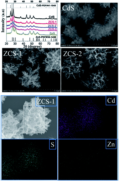 | ||
| Fig. 3 XRD patterns, SEM images and EDX mapping of the synthesized CdS and ZnxCd1−xS solid solutions. Reproduced from ref. 58 with permission. | ||
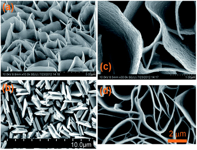 | ||
| Fig. 4 SEM images of the copper sulphide nanowalls oriented vertically to the copper foil anodized at 1.5 V at room temperature (a and c), and 3.0 V (b) and 1.5 V (d) at 5 °C. Reproduced from ref. 60 with permission. | ||
To engineer the bandgap energy of the photocatalyst that matches the solar spectrum, a solid solution with large and small bandgap semiconductors was proposed. For instance, Arai et al. used the Cu-based sulphide complex Cu2ZnSnS4 with a direct bandgap of 1.5 eV and a large optical absorption coefficient and obtained a high selectivity of the photoelectrochemical CO2 reduction reaction (>80%).68 The Cu-based sulphide complex reported by Liu et al. showcased that the Cu-based sulphide complex was able to reduce CO2 under visible light irradiation in the presence of a Ru co-catalyst.69 The Ru–CuxAgyInzZnkSm solid solutions induced the formation of methanol in CO2PR under visible light irradiation (Table 1 entry 6). Although the study reported that the optimal performance could be obtained through the elemental composition manipulation, the nanostructures of the sulphide complex were not revealed. It is therefore questionable whether the efficiency of these photocatalysts could be further enhanced through the manipulation of their microstructures. Moreover, the stability of metal sulphates in most of the studies has not been demonstrated, and this should be emphasized more in future work.
2.2 Oxides
Semiconducting oxides have been widely used as photocatalysts because of their stability and resistance to photocorrosion under irradiation. Hence, oxides have been used for photooxidation and photoreduction reactions. The intrinsic properties of metal oxides play a critical role in determining their feasibility for CO2PR. For example, CO2PR was observed for p-type NiO covalently linked with a Zn porphyrin light-harvesting sensitizer and rhenium bipyridine system, whereas the CO oxidation reaction was observed when a similar system was coupled with n-type NiO.70 There are two main groups of metal oxides with a closed-shell electronic configuration that have been at the centre of interest for a CO2PR system. The first group includes octahedrally coordinated d0 transition metal ions (Ti4+, Zr4+, Nb5+, Ta5+, V5+, and W6+). Apart from TiO2, which is the most prominent member of this group, other binary oxides (e.g., ZrO2, Nb2O5, and Ta2O5) have been used in CO2PR. A number of more complex oxides referred to as titanates, niobates, tantalates, etc.71,72 are often found in a perovskite composite, AMO3 (A = electropositive cation and M = transition metal; e.g., SrTiO3 and NaNbO3), or in perovskite-related structures. Since a recent published review has covered the use of perovskite oxide nanomaterials for CO2 photoreduction,73 this area will not be further discussed here. The second group includes main group metal oxides in a d10 configuration with a general formula of MyOz or AxMyO, where M represents Ga, Ge, In, Sn, or Sb. Many of these photocatalytically active binary and ternary oxides initially found application in photocatalytic water splitting, but they have very recently started to be utilised for CO2PR.73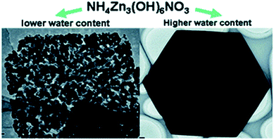 | ||
| Fig. 5 ZnO synthesized from NH4Zn3(OH)6NO3 with <3 mL (left) and >3 mL (right) of water. Reproduced from ref. 76 with permission. | ||
Doping has been widely used to extend the light absorption of wide bandgap semiconductors to a longer wavelength region by introducing intra-band states above the valence band. However, this approach tends to increase the recombination rate and decrease the charge mobility of the semiconductor, as discussed in Section 1. To avoid these drawbacks, the introduction of foreign cations into the binary semiconductor was considered instead of doping. For example, the ternary Zn2GeO4 semiconductor was used for CO2PR under UV-vis irradiation. By fabricating ultralong and ultrathin single crystal Zn2GeO4 nanoribbons, the photocatalytic reduction rate of CO2 into CH4 was greatly enhanced to 25.0 μmol gcatalyst−1 h−1 when compared to that of the bulk Zn2GeO4 (trace amounts, Table 1, entry 12).77 The enhanced photocatalytic efficiency was attributed to the superb crystal quality and higher surface area (28.3 m2 g−1) when compared to the bulk Zn2GeO4 (0.75 m2 g−1), resulting in enhanced separation of photogenerated electron–hole pairs and charge mobility. In the following year, the same group proposed the synthesis of the single crystal Zn2GeO4 at 40 °C to optimise the surface area.78 As a result, the surface area of the synthesized Zn2GeO4 nanorods was 33.1 m2 g−1 which yielded 179 and 35 ppm gcatalyst−1 h−1 of CO and CH4, respectively. Further increasing the temperature to 100 °C, however, decreased the surface area to 14.8 m2 g−1, yielding only 3.2 and 0.4 ppm h−1 of CO and CH4, respectively. By reducing the concentration of the Ge-precursor and the solvothermal time employed in the first study in 2010 (refer to ref. 77) by half, a sheaf-like superstructured Zn2GeO4 was obtained and reported by the same group in 2012 (Fig. 6).79 Although the CO2PR of the superstructured Zn2GeO4 was not reported in this study, the optimised RuO2 and Pt co-loaded Zn1.7GeN1.8O nano-sheaves after nitridation (32.33 m2 g−1) could produce CH4 with an apparent quantum yield of 0.024% at 450 nm (Table 1 entry 14).
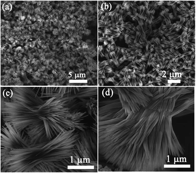 | ||
| Fig. 6 SEM images of a sheaf-like Zn2GeO4 superstructure at different magnifications. Reproduced from ref. 79 with permission. | ||
Other nanostructured ternary Zn-based oxides were also proposed by the same group more recently, including ZnGa2O nanosheet-scaffolded microspheres80 and hexagonal nanoplate-textured Zn2SnO4 with micro-octahedron architecture for CO2PR application.81 The unique architecture of the synthesized ZnGa2O and Zn2SnO4 significantly enhanced the separation of photogenerated electron–hole pairs, increased the surface area and extended light absorption. Hence, the methane yield obtained from the CO2PR was greatly improved from trace amounts to 69 and 47 ppm gcatalyst−1 h−1 for the nanostructured ZnGa2O and Zn2SnO4, respectively (Table 1, entries 15 and 16).
To promote co-adsorption of CO2 and H2O, Guo et al. fabricated ZnFe2O4 spinels doped with Ce.82 By using in situ FTIR, it was found that the CO2 amount adsorbed on the surface of Ce-doped ZnFe2O4 was much higher than that on pristine ZnFe2O4. This phenomenon was attributed to the increase of basicity due to the presence of alkaline CeO2 and electron density on the surface of the Ce-doped ZnFe2O4, thereby increasing the number of adsorption bonds between the CO2 molecules and the surface of the photocatalyst, and activating the O![[double bond, length as m-dash]](https://www.rsc.org/images/entities/char_e001.gif) C bond (Fig. 7). The formation of active b-CO32− and b-HCO3− species, which could be readily translated to highly valuable products in the CO2 photoreduction, was detected. Recently, Xiao et al. discovered that ultrafine ZnFe2O4 nanoparticles with a high specific surface area (112.9 m2 g−1) could promote the selectivity of the photoproduction of CH3CHO over CH3CH2OH, and they produced 57.8 and 13.7 μmol g−1 h−1, respectively, under visible light irradiation (>400 nm).105
C bond (Fig. 7). The formation of active b-CO32− and b-HCO3− species, which could be readily translated to highly valuable products in the CO2 photoreduction, was detected. Recently, Xiao et al. discovered that ultrafine ZnFe2O4 nanoparticles with a high specific surface area (112.9 m2 g−1) could promote the selectivity of the photoproduction of CH3CHO over CH3CH2OH, and they produced 57.8 and 13.7 μmol g−1 h−1, respectively, under visible light irradiation (>400 nm).105
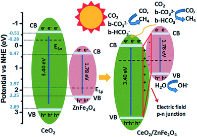 | ||
| Fig. 7 Schematic of the mechanism of CO2 photoreduction with H2O vapour over CeO2/ZnFe2O4. Reproduced from ref. 82 with permission. | ||
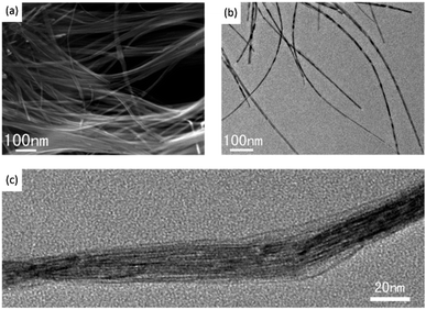 | ||
| Fig. 8 SEM (a), TEM (b) and high resolution TEM (c) images of W18O49. Reproduced from ref. 85 with permission. | ||
The introduction of foreign elements into tungsten oxide, which generated ternary Bi2WO6, was reported.86 The Bi2WO6 with predominant {001} facets was proposed to be the most energetically favoured reactive surface for CO2 dissociation, resulting in 1.1 μmol gcatalyst−1 h−1 of methane under visible light irradiation (λ > 420 nm), whereas the bulk Bi2WO6 prepared through a solid state reaction produced only trace amounts of methane. Cheng et al. also proposed that the microstructure of Bi2WO6 could enhance CO2 adsorption.87 A template-free anion exchange strategy was used to synthesize hollow microspheres of Bi2WO6 (Fig. 9a and b). The synthesized Bi2WO6 exhibited higher CO2 adsorption capacity when compared to BiVO4 and BiPO4 nanoparticles without hollow structures (Fig. 9c and d, respectively), leading to high photoconversion of CO2 into methanol.
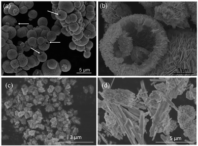 | ||
| Fig. 9 SEM images of Bi2WO6 hollow microspheres (a and b), BiVO4 (c) and BiPO4 (d) reproduced from ref. 87 with permission. | ||
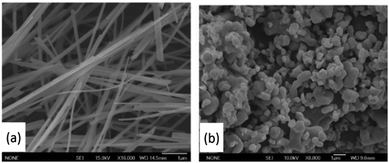 | ||
| Fig. 10 NaNbO3 nanowires (a) and bulk particles (b). Reproduced from ref. 88 with permission. | ||
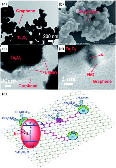 | ||
| Fig. 11 TEM (a) and SEM (b) images of Ta2O5 immobilised on reduced graphene. TEM (c) and SEM (d) images of the NiOx–Ta2O5-reduced graphene composite. Schematic illustration of the charge separation and transfer in the Ta2O5-reduced graphene system under UV-vis light (e). Reproduced from ref. 91 with permission. | ||
Much effort has focused on InTaO4 as the ternary tantalum-based semiconducting photocatalyst for CO2PR. For instance, Pan and Chen demonstrated that InTaO4 could reduce CO2 to methanol (∼1.1 μmol gcatalyst−1 h−1) in 0.2 M KHCO3 aqueous solution under visible light irradiation.110 The methanol production rate could marginally increase to 1.2 μmol gcatalyst−1 h−1 after coupling 1 wt% NiO as the co-catalyst and 1.4 μmol gcatalyst−1 h−1 after the application of reduction–oxidation pre-treatment. Tuning the size and crystallinity of InTaO4 nanoparticles resulted in the bandgap energy range from 2.6 to 3.0 eV and could also enhance the production of methanol from CO2.111 The highest production rate was about 2.7 μmol gcatalyst−1 h−1 when 1.0 wt% NiO was added as the co-catalyst. The methanol generation from InTaO4 was further enhanced by introducing core–shell Ni/NiO nanoparticles on nitrogen doped InTaO4, leading to 160 μmol gcatalyst−1 h−1 under the irradiation of light with wavelengths ranging from 390 to 770 nm.92 KTaO3 was also used to reduce CO2 to CO under visible light irradiation.112 Three samples were synthesized with different bandgaps ranging from 3.5 to 3.7 eV and yielded the highest amount of CO at ∼62 ppm gcatalyst−1 h−1.
Recently, LaTa7O19 and CaTa4O11 (bandgap energies of 4.1 and 4.5 eV, respectively) were shown to be active for CO2PR. CO was produced after loading with 1 wt% Ag co-catalyst due to the preferable conduction band positions (50 and 70 μmol gcatalyst−1 h−1, respectively, in the presence of 0.1 M NaHCO3 under the irradiation of a 400 W high-pressure mercury lamp).93 NaTaO3 doped with different elements, such as Mg, Ca, Sr, Ba and La, has been proposed as a highly active photocatalyst for CO2PR using water as the electron donor in the presence of a Ag co-catalyst under UV irradiation.94 Among the samples, Ba-doped NaTaO3 loaded with 1.0 wt% Ag co-catalyst using the liquid-phase reduction method exhibited the highest CO production and selectivity from CO2 (∼50 μmol gcatalyst−1 h−1 and 56%, respectively).
Quaternary tantalates have been developed recently and revealed to be active for CO2 photoreduction in the presence of water.113 K2RETa5O15 (RE = rare-earth element, namely La, Ce, Pr, Nd, Y, and Sm) was fabricated using the flux method with KCl, which favoured the rod-like morphology, followed by calcination treatment at 1150 °C for 6 h.95 Among the quaternary tantalates, K2CeTa5O15 possessed the smallest bandgap energy (2.42 eV, 0.7 μmol gcatalyst−1 h−1), but K2YTa5O15 photoproduced the highest amount of CO (3.86 eV, 91.9 μmol gcatalyst−1 h−1). The addition of Y was shown to be beneficial for capturing CO2 and subsequently for photoreduction. Meanwhile, the presence of K in the tantalates played an important role in determining the growth orientation of the rod-like structure, thereby affecting the activity in CO2 photoreduction.
MgO was employed to photocatalytically reduce CO2 into CO with a production rate of ∼1.6 μmol g−1 h−1 over 6 h in the presence of H2 as the reductant under UV light (λ < 290 nm).118 Mesoporous Ga2O3 yielded 1.46 and 0.21 μmol g−1 h−1 of CO and CH4, respectively, from CO2 under visible light irradiation.119 When Ga2O3 was loaded with Ag, the photoproduction rate of CO from CO2 was 10.5 μmol g−1 h−1 under UV light irradiation (Table 1 entry 33).96 Iron oxides were proposed as a photoactive centre to induce the photocatalytic reduction of CO2.120 Using electron spin resonance spectroscopy (ESR), the photogenerated electrons from the Fe–O species were efficiently consumed by CO2 under UV irradiation.
Lamellar BiVO4 was proposed to exhibit a selective methanol production from CO2 photoreduction under visible light irradiation.97 The maximum CH3OH production rate was 5.52 μmol h−1 when 0.2 g of BiVO4 was suspended in 100 mL of NaOH (1.0 M) under full spectrum irradiation of a Xe lamp. The photocatalytic mechanism was proposed according to which the Bi3+ sites could efficiently receive electrons from the V 3d-block bands of the BiVO4 to form CO2˙− radical anions, leading to the formation of methoxyl radicals (·OCH3) and eventually CH3OH after hydrogen abstraction. Wang et al. doped the atomically thin layers of BiVO4 with different percentages of Co.121 The Co-doped BiVO4 exhibited an efficient and stable activity for CO2 photoreduction to CH4. The optimal CH4 production rate was 23.8 μmol g−1 h−1, which was three times higher than that of the pristine BiVO4, at 60 °C with an atmospheric CO2 concentration (∼400 ppm) under a UV lamp (25 W at 254 nm). The enhancement of the production rate of the Co-doped BiVO4 was suggested to be due to the presence of electron enriched adsorption sites, which was contributed by the Co dopant, activating the CO2 molecules for further reduction reaction.
Delafossite materials with a general stoichiometry of ABO2, in which A is a monovalent metal ion, such as Cu, Ag, and Pt, and B is a trivalent metal ion, such as Al, Ga, and Fe, as the new class of photocatalysts have also been considered for CO2PR.98 CuGaO2 (bandgap energy ∼3.7 and weak absorption at 2.6 eV) and the Fe-alloyed CuGa1−xFexO (1.5 eV) facilitated the photogeneration of CO from CO2 under the irradiation of a Xe lamp though varied amounts of Fe substituted into CuGaO2 did not significantly enhance the CO2 photoreduction performance (Table 1 entry 35).98
Based on the Lewis acidity of CO2, alkaline catalysts will benefit the adsorption and activation of CO2. Layered double hydroxide (LDH) materials usually possess high specific surface areas, which provide numerous active sites for the catalytic reaction. The fabricated CoAl LDH facilitated an enhanced CO2 photoreduction reaction when compared to P25 due to the surface alkaline OH groups for efficient adsorption of CO2 at a low concentration.99 The utilisation of LDH in CO2 photoreduction has been reviewed previously, and thus, interested readers may refer to the published review articles.40,122
In summary, metal oxides have shown their ability to promote photocatalytic reduction of CO2, as discussed in the previous section. However, most of these photocatalysts only work under UV irradiation due to their large bandgap energies (>3 eV). The relatively large bandgap of metal oxides originates from the valence band maximum, which is formed by O 2p orbitals and is more positive than 3 V.123 Hence, if metal oxides meet the thermodynamic requirement for CO2PR and H2O photooxidation, then the bandgap of the metal oxides inevitably becomes larger than 3.0 eV, which is too wide to absorb visible light.124
2.3 Oxynitrides
![[thin space (1/6-em)]](https://www.rsc.org/images/entities/char_2009.gif) :
:![[thin space (1/6-em)]](https://www.rsc.org/images/entities/char_2009.gif) Ta molar ratio used in the proposed synthesis method was also beneficial to control the size and homogeneity of the final product. Recently, the use of the porous spherical architecture of TaON for CO2 photoreduction was proposed.100 The surface area of the porous spherical TaON was ∼11.12 m2 g−1, whereas that of commercial TaON was ∼7.41 m2 g−1. As a result, the CH3CHO and C2H5OH production rates from CO2 using the porous TaON (0.52 and 2.03 μmol gcatalyst−1 h−1) were higher when compared to those of the commercial TaON (0.16 and 0.84 μmol gcatalyst−1 h−1) under visible light irradiation. The enhanced CO2PR in the porous TaON was attributed to the increase of surface area. In addition, the reduction of charge transfer distance and enhanced light scattering within the porous spherical structure were also suggested to play roles in enhancing the photocatalytic reduction of CO2.
Ta molar ratio used in the proposed synthesis method was also beneficial to control the size and homogeneity of the final product. Recently, the use of the porous spherical architecture of TaON for CO2 photoreduction was proposed.100 The surface area of the porous spherical TaON was ∼11.12 m2 g−1, whereas that of commercial TaON was ∼7.41 m2 g−1. As a result, the CH3CHO and C2H5OH production rates from CO2 using the porous TaON (0.52 and 2.03 μmol gcatalyst−1 h−1) were higher when compared to those of the commercial TaON (0.16 and 0.84 μmol gcatalyst−1 h−1) under visible light irradiation. The enhanced CO2PR in the porous TaON was attributed to the increase of surface area. In addition, the reduction of charge transfer distance and enhanced light scattering within the porous spherical structure were also suggested to play roles in enhancing the photocatalytic reduction of CO2.
The CO2PR is a multi-electron process, and a variety of products can be produced using a single semiconducting photocatalyst. The achievement of efficient and selective production of highly valuable fuels is critical for viable CO2 photoreduction processes. The application of perovskite oxynitrides, such as CaTaO2N coupled with the binuclear Ru(II) complex photosensitiser and loaded with the Ag co-catalyst, revealed an enhanced selectivity for HCOOH production (>99%) from CO2 under visible light irradiation due to the enhanced interfacial electron transfer.128 A similar approach with the same photosensitiser and co-catalyst coupled with yttrium–tantalum oxynitride (YTON) was recently proposed by the same group.129 The YTON (2.1 eV) exhibited a smaller bandgap than CaTaO2N (2.5 eV), thus extending the light absorption up to 600 nm. Moreover, the selectivity for HCOOH formation from CO2 was not affected and remained as high as that in their previous study (>99%).
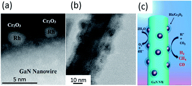 | ||
| Fig. 12 (a) High-resolution TEM image and (b) TEM image of Rh/Cr2O3 core/shell decorated GaN nanowires. (c) Schematic of the photoreduction processes of CO2 on Rh/Cr2O3-decorated GaN nanowires. Reproduced from ref. 102 with permission. | ||
2.4 Nitrides
In summary, both metal oxynitrides and nitrides have shown their capability to photoreduce CO2 with more favourable optical properties when compared to metal oxides. Unfortunately, these groups of materials have not been extensively explored.
3. Hole scavengers for CO2 photoreduction
Various semiconducting materials have been proposed as photocatalysts for CO2PR under UV and/or visible irradiation, as discussed in Section 2 and summarised in some other references.7–10,103,131 However, the quantum efficiency of the CO2 photo-conversion into hydrocarbons remained low and could not rely only on the development of photocatalysts. System optimisation plays an important role in optimising the conversion rate and selectivity as well as photocatalyst stability. Therefore, the increase of CO2PR efficiency through the introduction of a hole scavenging agent has gained significant interest. In this section, the use of organic and inorganic hole scavengers is reviewed.3.1 Inorganic hole scavengers
As discussed in Section 2.1, metal sulphides suffer from photocorrosion in an aqueous dispersion due to the oxidation of lattice S2− ions to elemental S and subsequently to sulphates.51 Hence, the addition of reducing agents to prevent the oxidation of the lattice S2− ions by scavenging the photogenerated holes was proposed. Kanemoto et al. achieved a cumulative quantum yield of 72% with irradiation of UV light at 313 nm (i.e., 75.1 and 1.7 μmol gcatalyst−1 h−1 of HCOOH and CO, respectively) when NaH2PO2 and Na2S (0.35 and 0.24 M, respectively) were added into the system that contained ZnS as the photocatalyst for CO2PR (Table 2 entry 1).132| No. | Photocatalyst | Hole scavenger | Function/role | Product(s) of CO2 photoreduction (μmol gcatalyst−1 h−1) | Ref. |
|---|---|---|---|---|---|
| Inorganic | |||||
| 1. | ZnS quantum crystallites | 0.70 M NaH2PO2 | Electron donor | HCOOH 75.10 | 132 |
| 0.48 M Na2S | Sulphur vacancy suppressor | CO 1.70 | |||
| 2. | ZnS | 0.1 M K2SO3 | Hole scavenger | HCOOH ∼250.00 | 134 |
| 0.1 M K2SO3+ | Electron donor | ||||
| 0.5 M KHCO3 | Buffer solution | HCOOH 580.30 | |||
| 3. | Zn-doped Ga2O3 | 0.1 M NaHCO3 | Hole scavenger | CO 117.00 | 138 |
| 4. | Ag-loaded SrNb2O6 | 0.1 M NaHCO3 | CO2 supply | CO ∼4.00 | 71 |
| 5. | Ag-loaded Sr2Nb2O7 | CO ∼38.40 | |||
| 6. | Sr and Ag co-loaded NaTaO3 | 0.1 M NaHCO3 | Buffer for supplying CO2 | CO ∼352.00 | 94 |
| 7. | Ni-Al layered double hydroxides (LDHs) | 0.1 M NaCl | Hole scavenger | CO 112.80 | 139 |
| 8. | BiVO4 | 1.0 M NaOH | Hole scavenger | CH3OH 5.52 | 97 |
![[thin space (1/6-em)]](https://www.rsc.org/images/entities/char_2009.gif) |
|||||
| Organic | |||||
| 9. | CdS | Acetonitrile + dichloromethane | Surface modifier | (CH3)2CO ∼0.24 μmol with 70 μM of CdS powder | 140 |
| Surface modifier | |||||
| 1.0 mol dm−3 2-propanol | Hole scavenger | (CH3)2CO ∼0.19 μmol with 70 μM of CdS powder | |||
| 10. | Wurtzite-ZnS | Isopropanol | Hole scavenger | HCOOH ∼40 ppm gcatalyst−1 h−1 | 141 |
| Ethylene glycol | Hole scavenger | HCOOH ∼90 ppm gcatalyst−1 h−1 | |||
| 11. | Mononuclear Ru complex/C3N4 | 4![[thin space (1/6-em)]](https://www.rsc.org/images/entities/char_2009.gif) : :![[thin space (1/6-em)]](https://www.rsc.org/images/entities/char_2009.gif) 1 of N,N-dimethylacetamide 1 of N,N-dimethylacetamide |
Proton quencher | HCOOH ∼1100.00 | 142 |
(DMA)![[thin space (1/6-em)]](https://www.rsc.org/images/entities/char_2009.gif) : :![[thin space (1/6-em)]](https://www.rsc.org/images/entities/char_2009.gif) triethanolamine (TEOA) triethanolamine (TEOA) |
Electron donor | ||||
| 12. | Bi-nuclear Ru complex/Ag-loaded C3N4 | 4![[thin space (1/6-em)]](https://www.rsc.org/images/entities/char_2009.gif) : :![[thin space (1/6-em)]](https://www.rsc.org/images/entities/char_2009.gif) 1 of N,N-dimethylacetamide 1 of N,N-dimethylacetamide |
Proton quencher | HCOOH ∼2115.00 | 143 |
(DMA)![[thin space (1/6-em)]](https://www.rsc.org/images/entities/char_2009.gif) : :![[thin space (1/6-em)]](https://www.rsc.org/images/entities/char_2009.gif) triethanolamine (TEOA) triethanolamine (TEOA) |
Electron donor | ||||
| 13. | Bi-nuclear Ru complex/Ag-loaded C3N4 | 1.0 mM ethylenediaminetetraacetic acid disodium salt dihydrate, EDTA·Na2 | Electron donor | HCOOH ∼31.67 | 144 |
| 14. | 1.0 mM ethylenediaminetetraacetic acid disodium salt dihydrate (EDTA·Na2) + 0.1 M K2CO3 | Electron donor | HCOOH ∼83.33 | ||
| Surface modifier | |||||
A systematic study was recently carried out to investigate the effect of Na2S as the hole scavenger for ZnS on the CO2PR at λ = 345 nm.133 The study elucidated that the photogenerated holes on the surface of ZnS were directly consumed by Na2S, whereas photogenerated electrons were pumped into the conduction band simultaneously. In addition, the behaviour of the reaction rate at different pH values resembled that of the solubility of CO2, discarding the direct participation of the HCO3− and CO32− in the photoreduction process. This observation was supported by a very recent study, in which KHCO3 was used as the hole scavenger in an aqueous system with ZnS.134 The study demonstrated that KHCO3 acted as an effective hole scavenger as well as a buffer to mitigate the pH change induced by the CO2 saturation. This phenomenon, however, was not observed when only K2SO3 was used as the hole scavenging agent.
The optimised solution with 0.1 g of colloidal ZnS, 0.1 M K2SO3 and 0.5 M KHCO3 achieved 464.2 and 81.3 μmol of HCOOH and CO, respectively, under UV-vis irradiation (Table 2 entry 2).134 The selectivity towards HCOOH was reported to be 12.5%, and this could be improved to 95.0% when Cd was added to the colloidal ZnS suspension as the co-catalyst.
Inorganic salts (e.g., NaOH, Na2S, etc.) have been reported to have a significant effect on CO2PR.97,132,134,135 The addition of NaOH had been shown to increase the solubility of CO2 compared to pure H2O because the OH− ions provided by NaOH in aqueous solution reacted with the dissolved CO2, and transformed into CO32− and further into HCO3− in the CO2 saturated system.136 It was suggested that the high concentration of HCO3− present in the system could accelerate the photoreduction reaction, thereby enhancing the photoreduction performance.136,137 The direct consumption of HCO32− to produce CO was observed in a CO2 aqueous solution using a Zn-doped Ga2O3 photocatalyst.138 This observation was further investigated by Nakanishi et al., in which the production of CO occurred after transforming HCO3− into CO2.94 Therefore, the addition of HCO3− increased the CO2 supply in the aqueous system, but did not enhance the numbers of reacted electrons and holes. In other words, under basic conditions, H2 production could be significantly suppressed, resulting in a high selectivity of CO from CO2. Jin et al. concurred that the addition of NaOH promoted the formation of HCO3−; however, the production of methanol was observed in the photocatalytic system with a BiVO4 photocatalyst.97
The addition of NaOH, Na2CO3 and NaHCO3 to the CO2 photoreduction aqueous solution was shown to promote the photoproduction of CO, whereas H2SO4 and NaCl were found to favour water splitting, leading to the production of H2.90,94,136,137 However, a recent study has proposed that the inclusion of Cl− from NaCl could scavenge the photogenerated holes for the CO2 photocatalytic reduction process in a aqueous solution over Ni–Al layered double hydroxides.139 The selectivity towards CO over H2 was 86% when NaCl was added into the photoreduction system (∼6.95 and ∼1.16 μmol g−1 h−1 of CO and H2, respectively), whereas in the absence of a scavenging agent, the selectivity towards CO over H2 was only 54% (∼3.15 and ∼2.63 μmol g−1 h−1 of CO and H2, respectively). The authors also pointed out that the addition of NaHCO3 and Na2CO3 promoted the production of H2via the reduction of H+ derived from H2O instead of the CO2PR. Neither Na2SO4 nor NaNO3 could positively enhance the production of CO. A similar extent of CO evolution and selectivity were also observed when other chloride salts were added, namely CsCl (∼8 μmol g−1 h−1 of CO, 82%), MgCl2 (∼7 μmol g−1 h−1 of CO, 82%) and CaCl2 (∼7.5 μmol g−1 h−1 of CO, 82%). However, other halogenide salts (NaBr and NaI) showed a weaker photoreduction ability than NaCl.
3.2 Organic hole scavengers
Since the last century, ZnS had been used as photocatalyst for the CO2PR.146,147 Triethylamine (TEA) showed its feasibility to be used as the hole scavenger, inhibiting the photocorrosion for sulphite photocatalysts.7 In ZnS systems, 2-propanol was one of the common hole scavengers for CO2PR. A previous report proposed that the light energy could be stored within the light-induced reaction given as| CO2 + (CH3)2CHOH → HCOOH + (CH3)2CO |
The Gibbs free energy of this reaction is +62.8 kJ mol−1 at 25 °C.147
In a system of Cd-loaded ZnS, CO2 photoproduced formic acid with a quantum efficiency 32.5% in the presence of 1 M 2-propanol.147 Further increasing the Cd concentration resulted in the formation of CO. A study revealed that CdS was capable of photoreducing CO2 to CO when N,N-dimethylformamide (DMF) containing 1 v/v% water was employed in the system.148 A similar observation was reported, in which CO was photoproduced when CdS was dispersed in DMF under the irradiation of a 500 W mercury lamp with a 300 nm cut off filter.140 When DMF was substituted with a low polarity solvent, such as CCl4 and CH2Cl2, CO production was dominant, whereas when using a high polar solvent, such as H2O, formate was produced. This was because the adsorbability of the CO2˙−, an intermediate species after the activation of CO2, was strongly dependent on the polarity of the solvent used. For instance, low polarity molecules enabled strong adsorption of CO2˙− on the Cd sites of CdS through the carbon atom of CO2˙−, which was not highly solvated in solvents of low polarity, resulting in the formation of CO. When high polar solvents were used, CO2˙− was stabilised in the system and established only weak interactions with the photocatalyst. As a result, CO2˙− tended to react with a proton and produced formate.
A recent study suggested that the CO2 photoreduction process can be greener when glycerol, which is a green solvent derived from vegetable oil, was used as the hole scavenger instead of petroleum-derived solvents.141 In this study, wurtzite ZnS facilitated the photoproduction of formic acid from CO2 with an apparent quantum efficiency of 3.2% and 0.9% when glycerol and 2-propanol, respectively, were employed as the hole scavenger.
Cyclohexanol was used as the hole scavenger for the CO2 photoreduction under UV light irradiation.149 The optimised sample exhibited the production of cyclohexyl formate and cyclohexanone (178.1 and 170.2 μmol gcatalyst−1, respectively) after 8 h. The authors elucidated that the production of cyclohexanone was slightly lower than that of cyclohexyl formate because some of the photogenerated holes were consumed by cyclohexanol to form cyclohexyl ether.
A recent study demonstrated that a Ru(II)-complex/C3N4 nanocomposite could induce the photocatalytic CO2 reduction by using a mixture of solvents (N,N-dimethylacetamide and DMA/TEOA).142 The apparent quantum efficiency achieved was 5.7% at 400 nm (Table 2 Entry 12). In addition, the product selectivity of the Ru(II)-complex/C3N4 nanocomposite could be enhanced through manipulating the solvent used (Fig. 13).145
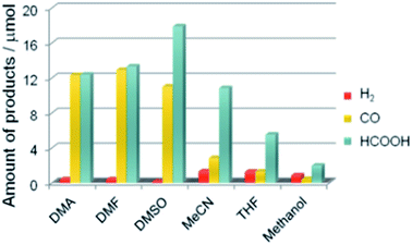 | ||
| Fig. 13 Product distribution of visible light (λ > 400 nm) CO2 reduction using Ru(II) complex/C3N4 as a photocatalyst and various solvents under a CO2 atmosphere (DMSO: dimethyl sulfoxide, MeCN: acetonitrile, and THF: tetrahydrofuran). Reproduced from ref. 145 with permission. | ||
In order to avoid using organic solvents as the medium, the mononuclear Ru(II) complex proposed in a previous study142 was replaced with a binuclear Ru(II) complex coupled with Ag/C3N4 and was employed as the photocatalyst (Table 2 entry 13).143 Since no reduction product was obtained in pure water, a hole scavenger (ethylenediaminetetraacetic acid disodium salt dihydrate, EDTA·Na2) was added to promote the photocatalytic CO2 reduction in water. The main product was HCOOH, and H2 was produced as a by-product under visible light irradiation (λ > 400 nm). Other hole scavenging agents (e.g., potassium oxalate and sodium ascorbate) were shown to be useful for the CO2PR. Among the three hole scavenging agents, sodium ascorbate exhibited the best performance with 31.7 μmol and 86% selectivity towards HCOOH. The HCOOH production could be further enhanced to 83.3 μmol with selectivity 97% when K2CO3 (0.1 M) was used as an additive.144 However, the production of H2 was reduced by half.
The introduction of organic and inorganic hole scavenging agents has exhibited advantages to enhance the efficiency of CO2PR. The presence of hole scavenging agents in the CO2PR process is necessary if the oxidation reaction in the CO2PR cannot be inhibited by the photocatalyst. Moreover, to avoid carbon contamination and false positive errors for the photogeneration of hydrocarbons in the CO2PR process, inorganic hole scavenging agents are preferred.
4. Conclusions and future directions
To date, significant achievements have been made in the design and fabrication of photocatalysts and the optimisation of photocatalytic systems. CO2PR using metal sulphides, oxides, oxynitrides and nitrides accumulated so far have offered alternative photocatalytic materials other than TiO2. Material properties, including the surface area, light harvesting, and charge generation, separation and transportation, have been manipulated through the structural and morphological control during the fabrication processes, leading to enhanced CO2PR performance. Amongst the non-titania photocatalysts (metal sulphides, oxides, oxynitrides and nitrides) reviewed here, the ultrathin W18O49 exhibited the highest CH4 yield (2200 μmol gcatalyst−1 h−1) from CO2 under visible light irradiation. The presence of oxygen vacancies was suggested to play an important role in the CO2PR. On the other hand, the addition of inorganic salts or organic solvents into an aqueous system has shown to effectively scavenge the photogenerated holes and/or increase CO2 solubility.Although significant studies have been carried out on CO2PR, some challenges still remain. Firstly, an in-depth understanding of the working mechanism in a CO2 photoreduction process is still not well understood. Hence, a trial-and-error approach was used when fabricating photocatalysts, attempting to achieve a high CO2PR efficiency. Secondly, the insight into the CO2PR in the presence of hole scavenging agent(s) is not available. Moreover, due to this lack of knowledge, a rational design to combine state-of-art of photocatalysts with the desired hole scavenging agent(s) for carbon fuel production is difficult to achieve. Therefore, while more effort is required in material advancement, studies of the combined effect of the proposed photocatalyst with a hole scavenger should be encouraged. In addition, further investigation of CO2PR at the molecular level through in situ characterisation techniques should be carried out as this is key to boosting the efficiency of CO2PR.
Conflicts of interest
There are no conflicts to declare.Acknowledgements
The authors acknowledge the financial support provided by the Engineering and Physical Sciences Research Council (EP/K021796/1), the Research Centre for Carbon Solutions (RCCS) and the Robert Buchan Chair in Sustainable Energy Engineering at Heriot-Watt University.References
- J. H. Montoya, L. C. Seitz, P. Chakthranont, A. Vojvodic, T. F. Jaramillo and J. K. Nørskov, Nat. Mater., 2016, 16, 70 CrossRef PubMed.
- IEA Finds CO2 Emissions Flat for Third Straight Year Even as Global Economy Grew in 2016, https://www.iea.org/newsroom/news/2017/march/iea-finds-co2-emissions-flat-for-third-straight-year-even-as-global-economy-grew.html.
- Forecast of Worldwide Carbon Dioxide Emissions through 2040, https://www.statista.com/statistics/263980/forecast-of-global-carbon-dioxide-emissions/.
- T. Inoue, A. Fujishima, S. Konishi and K. Honda, Nature, 1979, 277, 637–638 CrossRef CAS.
- K. R. Thampi, J. Kiwi and M. Gratzel, Nature, 1987, 327, 506–508 CrossRef CAS.
- Y. Y. Lee, H. S. Jung and Y. T. Kang, J. CO2 Util., 2017, 20, 163–177 CrossRef CAS.
- S. N. Habisreutinger, L. Schmidt-Mende and J. K. Stolarczyk, Angew. Chem., Int. Ed., 2013, 52, 7372–7408 CrossRef CAS PubMed.
- M. Marszewski, S. Cao, J. Yu and M. Jaroniec, Mater. Horiz., 2015, 2, 261–278 RSC.
- K. Li, X. An, K. H. Park, M. Khraisheh and J. Tang, Catal. Today, 2014, 224, 3–12 CrossRef CAS.
- J. L. White, M. F. Baruch, J. E. Pander, Y. Hu, I. C. Fortmeyer, J. E. Park, T. Zhang, K. Liao, J. Gu, Y. Yan, T. W. Shaw, E. Abelev and A. B. Bocarsly, Chem. Rev., 2015, 115, 12888–12935 CrossRef CAS PubMed.
- Y. Yamazaki, H. Takeda and O. Ishitani, J. Photochem. Photobiol., C, 2015, 25, 106–137 CrossRef CAS.
- P. Salvador, J. Appl. Phys., 1984, 55, 2977–2985 CrossRef CAS.
- O. Carp, C. L. Huisman and A. Reller, Prog. Solid State Chem., 2004, 32, 33–177 CrossRef CAS.
- O. Ola and M. M. Maroto-Valer, J. Photochem. Photobiol., C, 2015, 24, 16–42 CrossRef CAS.
- M. S. Akple, J. Low, Z. Qin, S. Wageh, A. A. Al-Ghamdi, J. Yu and S. Liu, Chin. J. Catal., 2015, 36, 2127–2134 CrossRef CAS.
- K. Sasan, F. Zuo, Y. Wang and P. Feng, Nanoscale, 2015, 7, 13369–13372 RSC.
- H. Zhao, L. Liu, J. M. Andino and Y. Li, J. Mater. Chem. A, 2013, 1, 8209–8216 RSC.
- S.-M. Park, A. Razzaq, Y. H. Park, S. Sorcar, Y. Park, C. A. Grimes and S.-I. In, ACS Omega, 2016, 1, 868–875 CrossRef CAS.
- J. Xiao, D. Mao, X. Guo and J. Yu, Energy Technol., 2015, 3, 32–39 CrossRef CAS.
- G. Qin, Y. Zhang, X. Ke, X. Tong, Z. Sun, M. Liang and S. Xue, Appl. Catal., B, 2013, 129, 599–605 CrossRef CAS.
- E.-G. Ha, J.-A. Chang, S.-M. Byun, C. Pac, D.-M. Jang, J. Park and S. O. Kang, Chem. Commun., 2014, 50, 4462–4464 RSC.
- Y. Liao, S.-W. Cao, Y. Yuan, Q. Gu, Z. Zhang and C. Xue, Chem. - Eur. J., 2014, 20, 10220–10222 CrossRef CAS PubMed.
- Q. Zhang, T. Gao, J. M. Andino and Y. Li, Appl. Catal., B, 2012, 123–124, 257–264 CrossRef CAS.
- J. Low, B. Cheng and J. Yu, Appl. Surf. Sci., 2017, 392, 658–686 CrossRef CAS.
- P. Reñones, A. Moya, F. Fresno, L. Collado, J. J. Vilatela and V. A. de la Peña O'Shea, J. CO2 Util., 2016, 15, 24–31 CrossRef.
- X. Chang, T. Wang and J. Gong, Energy Environ. Sci., 2016, 9, 2177–2196 RSC.
- H. Tong, S. Ouyang, Y. Bi, N. Umezawa, M. Oshikiri and J. Ye, Adv. Mater., 2012, 24, 229–251 CrossRef CAS PubMed.
- Z. Zhu, Y. Han, C. Chen, Z. Ding, J. Long and Y. Hou, ChemCatChem, 2018, 10, 1627–1634 CrossRef CAS.
- J. Yu, J. Jin, B. Cheng and M. Jaroniec, J. Mater. Chem. A, 2014, 2, 3407–3416 RSC.
- X. Li, J. Wen, J. Low, Y. Fang and J. Yu, Sci. China Mater., 2014, 57, 70–100 CrossRef.
- J.-y. Tang, R.-t. Guo, W.-g. Zhou, C.-y. Huang and W.-g. Pan, Appl. Catal., B, 2018, 237, 802–810 CrossRef CAS.
- P. Xia, B. Zhu, J. Yu, S. Cao and M. Jaroniec, J. Mater. Chem. A, 2017, 5, 3230–3238 RSC.
- W. Yu, D. Xu and T. Peng, J. Mater. Chem. A, 2015, 3, 19936–19947 RSC.
- M. Wang, J. Liu, C. Guo, X. Gao, C. Gong, Y. Wang, B. Liu, X. Li, G. G. Gurzadyan and L. Sun, J. Mater. Chem. A, 2018, 6, 4768–4775 RSC.
- N. Nie, F. He, L. Zhang and B. Cheng, Appl. Surf. Sci., 2018, 457, 1096–1102 CrossRef CAS.
- Y. Ma, Z. Wang, X. Xu and J. Wang, Chin. J. Catal., 2017, 38, 1956–1969 CrossRef CAS.
- H. Zhao, X. Yang, R. Xu, J. Li, S. Gao and R. Cao, J. Mater. Chem. A, 2018, 6, 20152–20160 RSC.
- Y. Chen, D. Wang, X. Deng and Z. Li, Catal. Sci. Tech., 2017, 7, 4893–4904 RSC.
- S. Ye, R. Wang, M.-Z. Wu and Y.-P. Yuan, Appl. Surf. Sci., 2015, 358, 15–27 CrossRef CAS.
- A. Nikokavoura and C. Trapalis, Appl. Surf. Sci., 2017, 391, 149–174 CrossRef CAS.
- X. Chen, S. Shen, L. Guo and S. S. Mao, Chem. Rev., 2010, 110, 6503–6570 CrossRef CAS PubMed.
- K. Maeda and K. Domen, J. Phys. Chem. C, 2007, 111, 7851–7861 CrossRef CAS.
- K. Maeda and K. Domen, J. Phys. Chem. Lett., 2010, 1, 2655–2661 CrossRef CAS.
- G. Liu, P. Niu, C. Sun, S. C. Smith, Z. Chen, G. Q. Lu and H.-M. Cheng, J. Am. Chem. Soc., 2010, 132, 11642–11648 CrossRef CAS PubMed.
- W.-N. Wang, W.-J. An, B. Ramalingam, S. Mukherjee, D. M. Niedzwiedzki, S. Gangopadhyay and P. Biswas, J. Am. Chem. Soc., 2012, 134, 11276–11281 CrossRef CAS PubMed.
- Y. Wei, J. Jiao, Z. Zhao, W. Zhong, J. Li, J. Liu, G. Jiang and A. Duan, J. Mater. Chem. A, 2015, 3, 11074–11085 RSC.
- Z. Hu, M. Xu, Z. Shen and J. C. Yu, J. Mater. Chem. A, 2015, 3, 14046–14053 RSC.
- F. R. F. Fan, P. Leempoel and A. J. Bard, J. Electrochem. Soc., 1983, 130, 1866–1875 CrossRef CAS.
- K. Kočí, L. Matějová, O. Kozák, L. Čapek, V. Valeš, M. Reli, P. Praus, K. Šafářová, A. Kotarba and L. Obalová, Appl. Catal., B, 2014, 158–159, 410–417 CrossRef.
- P. Johne and H. Kisch, J. Photochem. Photobiol., A, 1997, 111, 223–228 CrossRef CAS.
- D. Meissner, R. Memming and B. Kastening, J. Phys. Chem., 1988, 92, 3476–3483 CrossRef CAS.
- X. Meng, G. Zuo, P. Zong, H. Pang, J. Ren, X. Zeng, S. Liu, Y. Shen, W. Zhou and J. Ye, Appl. Catal., B, 2018, 237, 68–73 CrossRef CAS.
- C. Yang, Q. Li, Y. Xia, K. Lv and M. Li, Appl. Surf. Sci., 2019, 464, 388–395 CrossRef CAS.
- Y. Chai, J. Lu, L. Li, D. Li, M. Li and J. Liang, Catal. Sci. Tech., 2018, 8, 2697–2706 RSC.
- Z. Zhu, J. Qin, M. Jiang, Z. Ding and Y. Hou, Appl. Surf. Sci., 2017, 391, 572–579 CrossRef CAS.
- H. Kisch and P. Lutz, Photochem. Photobiol. Sci., 2002, 1, 240–245 RSC.
- K. Kočí, P. Praus, M. Edelmannová, A. Nela, N. ová, I. Troppová, D. Fridrichová, G. owik and J. Ryczkowski, J. Nanosci. Nanotechnol., 2017, 17, 4041–4047 CrossRef.
- P. Li, X. Zhang, C. Hou, L. Lin, Y. Chen and T. He, Phys. Chem. Chem. Phys., 2018, 20, 16985–16991 RSC.
- X. Li, J. Chen, H. Li, J. Li, Y. Xu, Y. Liu and J. Zhou, J. Nat. Gas Chem., 2011, 20, 413–417 CrossRef CAS.
- P. Kar, S. Farsinezhad, X. Zhang and K. Shankar, Nanoscale, 2014, 6, 14305–14318 RSC.
- J. Jin and T. He, Appl. Surf. Sci., 2017, 394, 364–370 CrossRef CAS.
- J. Jin, J. Yu, D. Guo, C. Cui and W. Ho, Small, 2015, 11, 5262–5271 CrossRef CAS PubMed.
- W. Li, D. Li, W. Zhang, Y. Hu, Y. He and X. Fu, J. Phys. Chem. C, 2010, 114, 2154–2159 CrossRef CAS.
- Q. Li, H. Meng, P. Zhou, Y. Zheng, J. Wang, J. Yu and J. Gong, ACS Catal., 2013, 3, 882–889 CrossRef CAS.
- Z. Han, G. Chen, C. Li, Y. Yu and Y. Zhou, J. Mater. Chem. A, 2015, 3, 1696–1702 RSC.
- Y. Zhao, H. Pan, Y. Lou, X. Qiu, J. Zhu and C. Burda, J. Am. Chem. Soc., 2009, 131, 4253–4261 CrossRef CAS PubMed.
- W. Liang and M. H. Whangbo, Solid State Commun., 1993, 85, 405–408 CrossRef CAS.
- T. Arai, S. Tajima, S. Sato, K. Uemura, T. Morikawa and T. Kajino, Chem. Commun., 2011, 47, 12664–12666 RSC.
- J.-Y. Liu, B. Garg and Y.-C. Ling, Green Chem., 2011, 13, 2029–2031 RSC.
- A. Bachmeier, S. Hall, S. W. Ragsdale and F. A. Armstrong, J. Am. Chem. Soc., 2014, 136, 13518–13521 CrossRef CAS.
- A. Kubacka, M. Fernández-García and G. Colón, Chem. Rev., 2012, 112, 1555–1614 CrossRef CAS PubMed.
- H. W. Eng, P. W. Barnes, B. M. Auer and P. M. Woodward, J. Solid State Chem., 2003, 175, 94–109 CrossRef CAS.
- Z. Sheng, K. Piyush, T. Ujwal Kumar and S. Karthik, Nanotechnology, 2018, 29, 052001 CrossRef PubMed.
- A. H. Yahaya, M. A. Gondal and A. Hameed, Chem. Phys. Lett., 2004, 400, 206–212 CrossRef CAS.
- J. Núñez, V. A. de la Peña O'Shea, P. Jana, J. M. Coronado and D. P. Serrano, Catal. Today, 2013, 209, 21–27 CrossRef.
- L. Wan, X. Wang, S. Yan, H. Yu, Z. Li and Z. Zou, CrystEngComm, 2012, 14, 154–159 RSC.
- Q. Liu, Y. Zhou, J. Kou, X. Chen, Z. Tian, J. Gao, S. Yan and Z. Zou, J. Am. Chem. Soc., 2010, 132, 14385–14387 CrossRef CAS PubMed.
- S. Yan, L. Wan, Z. Li and Z. Zou, Chem. Commun., 2011, 47, 5632–5634 RSC.
- Q. Liu, Y. Zhou, Z. Tian, X. Chen, J. Gao and Z. Zou, J. Mater. Chem., 2012, 22, 2033–2038 RSC.
- Q. Liu, D. Wu, Y. Zhou, H. Su, R. Wang, C. Zhang, S. Yan, M. Xiao and Z. Zou, ACS Appl. Mater. Interfaces, 2014, 6, 2356–2361 CrossRef CAS.
- Z. Li, Y. Zhou, J. Zhang, W. Tu, Q. Liu, T. Yu and Z. Zou, Cryst. Growth Des., 2012, 12, 1476–1481 CrossRef CAS.
- J. Guo, K. Wang and X. Wang, Catal. Sci. Tech., 2017, 7, 6013–6025 RSC.
- Y. P. Xie, G. Liu, L. Yin and H.-M. Cheng, J. Mater. Chem., 2012, 22, 6746–6751 RSC.
- X. Chen, Y. Zhou, Q. Liu, Z. Li, J. Liu and Z. Zou, ACS Appl. Mater. Interfaces, 2012, 4, 3372–3377 CrossRef CAS PubMed.
- G. Xi, S. Ouyang, P. Li, J. Ye, Q. Ma, N. Su, H. Bai and C. Wang, Angew. Chem., Int. Ed., 2012, 51, 2395–2399 CrossRef CAS PubMed.
- Y. Zhou, Z. Tian, Z. Zhao, Q. Liu, J. Kou, X. Chen, J. Gao, S. Yan and Z. Zou, ACS Appl. Mater. Interfaces, 2011, 3, 3594–3601 CrossRef CAS PubMed.
- H. Cheng, B. Huang, Y. Liu, Z. Wang, X. Qin, X. Zhang and Y. Dai, Chem. Commun., 2012, 48, 9729–9731 RSC.
- H. Shi, T. Wang, J. Chen, C. Zhu, J. Ye and Z. Zou, Catal. Lett., 2011, 141, 525–530 CrossRef CAS.
- X. Li, H. Pan, W. Li and Z. Zhuang, Appl. Catal., A, 2012, 413–414, 103–108 CrossRef CAS.
- R. Pang, K. Teramura, H. Asakura, S. Hosokawa and T. Tanaka, Appl. Catal., B, 2017, 218, 770–778 CrossRef CAS.
- X.-J. Lv, W.-F. Fu, C.-Y. Hu, Y. Chen and W.-B. Zhou, RSC Adv., 2013, 3, 1753–1757 RSC.
- C.-W. Tsai, H. M. Chen, R.-S. Liu, K. Asakura and T.-S. Chan, J. Phys. Chem. C, 2011, 115, 10180–10186 CrossRef CAS.
- T. Takayama, H. Nakanishi, M. Matsui, A. Iwase and A. Kudo, J. Photochem. Photobiol., A, 2017, 358, 416–421 CrossRef.
- H. Nakanishi, K. Iizuka, T. Takayama, A. Iwase and A. Kudo, ChemSusChem, 2017, 10, 112–118 CrossRef CAS PubMed.
- Z. Huang, K. Teramura, H. Asakura, S. Hosokawa and T. Tanaka, Catal. Today, 2018, 300, 173–182 CrossRef CAS.
- M. Yamamoto, T. Yoshida, N. Yamamoto, H. Yoshida and S. Yagi, e-J. Surf. Sci. Nanotechnol., 2014, 12, 299–303 CrossRef CAS.
- J. Mao, T. Peng, X. Zhang, K. Li and L. Zan, Catal. Commun., 2012, 28, 38–41 CrossRef CAS.
- J. W. Lekse, M. K. Underwood, J. P. Lewis and C. Matranga, J. Phys. Chem. C, 2012, 116, 1865–1872 CrossRef CAS.
- K. Wang, L. Zhang, Y. Su, D. Shao, S. Zeng and W. Wang, J. Mater. Chem. A, 2018, 6, 8366–8373 RSC.
- Q. Han, Y. Zhou, L. Tang, P. Li, W. Tu, L. Li, H. Li and Z. Zou, RSC Adv., 2016, 6, 90792–90796 RSC.
- S. Yan, H. Yu, N. Wang, Z. Li and Z. Zou, Chem. Commun., 2012, 48, 1048–1050 RSC.
- B. AlOtaibi, S. Fan, D. Wang, J. Ye and Z. Mi, ACS Catal., 2015, 5, 5342–5348 CrossRef CAS.
- T.-M. Su, Z.-z. Qin, H.-B. Ji, Y.-x. Jiang and G. Huang, Environ. Chem. Lett., 2016, 14, 99–112 CrossRef CAS.
- G. Mahmodi, S. Sharifnia, F. Rahimpour and S. N. Hosseini, Sol. Energy Mater. Sol. Cells, 2013, 111, 31–40 CrossRef CAS.
- J. Xiao, W. Yang, S. Gao, C. Sun and Q. Li, J. Mater. Sci. Technol., 2018, 34, 2331–2336 CrossRef.
- G. R. Bamwenda and H. Arakawa, Appl. Catal., A, 2001, 210, 181–191 CrossRef CAS.
- S. Xie, Y. Wang, Q. Zhang, W. Deng and Y. Wang, Chem. Commun., 2015, 51, 3430–3433 RSC.
- W.-J. Chun, A. Ishikawa, H. Fujisawa, T. Takata, J. N. Kondo, M. Hara, M. Kawai, Y. Matsumoto and K. Domen, J. Phys. Chem. B, 2003, 107, 1798–1803 CrossRef CAS.
- S. Sato, T. Morikawa, S. Saeki, T. Kajino and T. Motohiro, Angew. Chem., Int. Ed., 2010, 49, 5101–5105 CrossRef CAS PubMed.
- P.-W. Pan and Y.-W. Chen, Catal. Commun., 2007, 8, 1546–1549 CrossRef CAS.
- H.-C. Chen, H.-C. Chou, J. C. S. Wu and H.-Y. Lin, J. Mater. Res., 2011, 23, 1364–1370 CrossRef.
- K. Li, A. D. M. Handoko, M. Khraisheh and J. Tang, Nanoscale, 2014, 6, 9767–9773 RSC.
- Z. Huang, K. Teramura, S. Hosokawa and T. Tanaka, Appl. Catal., B, 2016, 199, 272–281 CrossRef CAS.
- L. Chen, D. Meng, X. Wu, A. Wang, J. Wang, Y. Wang and M. Yu, J. Phys. Chem. C, 2016, 120, 18548–18559 CrossRef CAS.
- X.-J. Wen, C.-G. Niu, L. Zhang, C. Liang and G.-M. Zeng, Appl. Catal., B, 2018, 221, 701–714 CrossRef CAS.
- W. Xiong, W. Dai, X. Hu, L. Yang, T. Wang, Y. Qin, X. Luo and J. Zou, Mater. Lett., 2018, 232, 36–39 CrossRef CAS.
- Q. Zhang, M. Mao, Y. Li, Y. Yang, H. Huang, Z. Jiang, Q. Hu, S. Wu and X. Zhao, Appl. Catal., B, 2018, 239, 555–564 CrossRef CAS.
- Y. Kohno, H. Ishikawa, T. Tanaka, T. Funabiki and S. Yoshida, Phys. Chem. Chem. Phys., 2001, 3, 1108–1113 RSC.
- H.-a. Park, J. H. Choi, K. M. Choi, D. K. Lee and J. K. Kang, J. Mater. Chem., 2012, 22, 5304–5307 RSC.
- Y. Tong, Y. Zhang, N. Tong, Z. Zhang, Y. Wang, X. Zhang, S. Zhu, F. Li and X. Wang, Catal. Sci. Tech., 2016, 6, 7579–7585 RSC.
- K. Wang, L. Zhang, Y. Su, S. Sun, Q. Wang, H. Wang and W. Wang, Catal. Sci. Tech., 2018, 8, 3115–3122 RSC.
- Y. Chen, G. Jia, Y. Hu, G. Fan, Y. H. Tsang, Z. Li and Z. Zou, Sustainable Energy Fuels, 2017, 1, 1875–1898 RSC.
- D. E. Scaife, Sol. Energy, 1980, 25, 41–54 CrossRef CAS.
- K. Maeda, Prog. Solid State Chem., 2018, 51, 52–62 CrossRef CAS.
- K. Maeda, Phys. Chem. Chem. Phys., 2013, 15, 10537–10548 RSC.
- M. Hara, G. Hitoki, T. Takata, J. N. Kondo, H. Kobayashi and K. Domen, Catal. Today, 2003, 78, 555–560 CrossRef CAS.
- Q. Gao, C. Giordano and M. Antonietti, Small, 2011, 7, 3334–3340 CrossRef CAS PubMed.
- F. Yoshitomi, K. Sekizawa, K. Maeda and O. Ishitani, ACS Appl. Mater. Interfaces, 2015, 7, 13092–13097 CrossRef CAS PubMed.
- K. Muraoka, H. Kumagai, M. Eguchi, O. Ishitani and K. Maeda, Chem. Commun., 2016, 52, 7886–7889 RSC.
- N. Zhang, S. Ouyang, T. Kako and J. Ye, Chem. Commun., 2012, 48, 1269–1271 RSC.
- H. L. Tuller, Mater. Renewable Sustainable Energy, 2017, 6, 3 CrossRef PubMed.
- M. Kanemoto, T. Shiragami, C. Pac and S. Yanagida, J. Phys. Chem., 1992, 96, 3521–3526 CrossRef CAS.
- R. Zhou and M. I. Guzman, J. Phys. Chem. C, 2014, 118, 11649–11656 CrossRef CAS.
- X. Meng, Q. Yu, G. Liu, L. Shi, G. Zhao, H. Liu, P. Li, K. Chang, T. Kako and J. Ye, Nano Energy, 2017, 34, 524–532 CrossRef CAS.
- S. Kaneco, Y. Shimizu, K. Ohta and T. Mizuno, J. Photochem. Photobiol., A, 1998, 115, 223–226 CrossRef CAS.
- I. H. Tseng, W.-C. Chang and J. C. S. Wu, Appl. Catal., B, 2002, 37, 37–48 CrossRef CAS.
- S. Liu, Z. Zhao and Z. Wang, Photochem. Photobiol. Sci., 2007, 6, 695–700 RSC.
- K. Teramura, Z. Wang, S. Hosokawa, Y. Sakata and T. Tanaka, Chem. Eur. J. , 2014, 20, 9906–9909 CrossRef CAS.
- S. Iguchi, K. Teramura, S. Hosokawa and T. Tanaka, Phys. Chem. Chem. Phys., 2015, 17, 17995–18003 RSC.
- B.-J. Liu, T. Torimoto and H. Yoneyama, J. Photochem. Photobiol., A, 1998, 113, 93–97 CrossRef CAS.
- D. P. Leonard, H. Pan and M. D. Heagy, ACS Appl. Mater. Interfaces, 2016, 8, 1553 CrossRef CAS.
- R. Kuriki, K. Sekizawa, O. Ishitani and K. Maeda, Angew. Chem., Int. Ed., 2015, 54, 2406–2409 CrossRef CAS PubMed.
- R. Kuriki, H. Matsunaga, T. Nakashima, K. Wada, A. Yamakata, O. Ishitani and K. Maeda, J. Am. Chem. Soc., 2016, 138, 5159–5170 CrossRef CAS.
- R. Kuriki, M. Yamamoto, K. Higuchi, Y. Yamamoto, M. Akatsuka, D. Lu, S. Yagi, T. Yoshida, O. Ishitani and K. Maeda, Angew. Chem., Int. Ed., 2017, 56, 4867–4871 CrossRef CAS PubMed.
- R. Kuriki, O. Ishitani and K. Maeda, ACS Appl. Mater. Interfaces, 2016, 8, 6011–6018 CrossRef CAS PubMed.
- I. Hiroshi, T. Tsukasa, S. Takao, M. Hirotaro and Y. Hiroshi, Chem. Lett., 1990, 19, 1483–1486 CrossRef.
- H. Inoue, H. Moriwaki, K. Maeda and H. Yoneyama, J. Photochem. Photobiol., A, 1995, 86, 191–196 CrossRef CAS.
- K. Masashi, I. Ken-ichi, W. Yuji, S. Takao, M. Hirotaro and Y. Shozo, Chem. Lett., 1992, 21, 835–836 CrossRef.
- G. Song, F. Xin and X. Yin, J. Colloid Interface Sci., 2015, 442, 60–66 CrossRef CAS PubMed.
| This journal is © The Royal Society of Chemistry 2019 |


