Methane dry reforming catalyst prepared by the co-deflagration of high-nitrogen energetic complexes†
Moran
Dahan‡
a,
Eswaravara
Komarala‡
 a,
Ludmila
Fadeev
b,
Ajay K.
Chinnam
 b,
Avital
Shlomovich
b,
Sophia
Lipstman
b,
Siva P.
Padi
b,
Herman
Haustein
c,
Michael
Gozin
b,
Avital
Shlomovich
b,
Sophia
Lipstman
b,
Siva P.
Padi
b,
Herman
Haustein
c,
Michael
Gozin
 b and
Brian A.
Rosen
 *a
*a
aDepartment of Materials Science and Engineering, Tel Aviv University, Tel Aviv, Israel 69987001. E-mail: barosen@post.tau.ac.il
bSchool of Chemistry, Tel Aviv University, Tel Aviv, Israel 69987001
cDepartment of Mechanical Engineering, Tel Aviv University, Tel Aviv, Israel 69987001
First published on 12th November 2018
Abstract
Methane dry reforming presents a unique opportunity to simultaneously consume both methane and carbon dioxide and generate from them clean-burning synthetic fuels for mobile energy applications. The industrialization of CH4 dry reforming has been impeded mainly due to problems relating to the catalyst–support interface including sintering and carbon accumulation. Here, we present a new methodology, termed co-deflagration, for the synthesis of a stable supported catalyst for methane dry reforming. Co-deflagration utilizes the energy released during the decomposition of high-nitrogen energetic ligands bound to a metal atom. During co-deflagration, the metal atoms crystallize into the supported catalyst material. Here, we used the co-deflagration technique to synthesize Ni/La2O2CO3 for use in methane dry reforming. We intended that the high thermal and kinetic energy imparted to La and Ni atoms during the energetic deflagration process would give rise to strong interfacial interaction between the catalyst and support and therefore stabilize catalytic activity. Ni/La2O2CO3 synthesized using co-deflagration showed stable performance under CH4 dry reforming conditions at elevated gas-hourly space velocities.
Introduction
Nitrogen-rich energetic materials (EMs) belong to a class of compounds that can release a significant amount of energy and gases upon their deflagration or detonation. These materials are commonly used as explosives, propellants, pyrotechnics, and as gas generators.1 Here, we present an entirely novel use of these materials as the primary component in a process to create highly stable supported catalysts for energy storage and conversion applications. In recent years, nitrogen-rich EMs have undergone extensive research and development due to the capability of such materials to release N2 as the main combustion product (“green” EMs). During an investigation of the combustion behaviour of various complexes of nitrogen-rich ligands for use in pyrotechnics, Tappan and co-workers found a novel way of synthesizing ultralow-density monolithic metal nanofoams.2 This was achieved by self-propagating combustion of energetic metal complexes containing nitrogen-rich ligands. These researchers showed that the combustion behaviour of the energetic metal complex played an important role in determining the metal nanofoam structure in an apparent “Goldilocks” effect. They found that energetic complexes that were too sensitive to mechanical impact and friction (“too hot”) detonated rapidly and failed to create monolithic foams, while complexes which were too inert (“too cold”) could not sustain a self-propagating combustion process. The use of such metal nanofoams in catalytic systems and other applications was recently reported. For example, gold nanofoams showed modest activity as electrocatalysts,3 while self-combustion generated palladium nanofoams were investigated as a material for H2 storage.2 The latter Pd nanofoams showed a low capacity for storage of H2 compared to bulk Pd metal (in a powdered form), possibly due to a presence of combustion-related impurities and residues. In addition to the synthesis of metal nanofoams, the only other reported use of high-nitrogen EMs for metal synthesis was from Qu and coworkers who made copper micro-rods by thermal decomposition of the Cu–[bis(1H-tetrazol-5-yl)amine]2 (Cu(BTA)2) complex under inert atmosphere.4While some transition-metal bis(1H-tetrazol-5-yl)amine (BTA) complexes have been previously described, lanthanide complexes with any energetic ligand are far less developed. Previously synthesized salts and complexes of nitrogen-rich energetic ligands with lanthanides include 5,5′-bitetrazolate (BT) with various lanthanides (La, Ce, Nd, Sm, Eu, Tb and Er), 1,3-bis(tetrazol-5-yl)-triazenate (BTT) with Sm, Nd, Eu and Er,5 5,5′-azotetrazolate (ZT) with La, Ce, Nd and Gd,6 and 1,3-benzeneditetrazol-5-yl (m-BDTH) with La, Ho, Er, Yb and Lu.7 A series of lanthanide–BTA complexes were also reported, including Ln(BTA)(HCOO)(H2O)3 (Ln = Pr, Gs, Eu, Tb, Dy, Er, Yb).8 Although Shen and coworkers synthesized complexes with a ligand called DATZA (N,N′-bis(tetrazol-5-yl)amine-N2,N2′-diacetic acid) containing the BTA moiety with La coordinated by carboxylic groups, to our knowledge, no other complexes of lanthanum and the BTA ligand have been reported.
Here, we report the synthesis of a supported nanocatalyst prepared by the co-deflagration of a mixture of two high-nitrogen energetic metal complexes containing nickel and lanthanum. We define co-deflagration as the simultaneous combustion of at least two metal-containing energetic complexes resulting in the sub-sonic release of gases as well as a solid-phase product. BTA complexes were selected as they are both safe to handle and powerful enough to sustain efficient deflagration. Our goal was to prepare the Ni/La2O2CO3 supported catalyst by co-deflagrating energetic mixtures of nitrogen-rich ligands. We intended that the kinetic energy available to Ni and La atoms during the crystallization process would give rise to strong catalyst–support interactions and therefore stable catalytic activity. Ni/La2O2CO3 was selected as our target since it has a great potential to enable the large-scale industrialization of CH4 dry reforming (reaction (1)). Methane dry reforming is highly important, due to its consumption of two green-house gases .9,10
| CH4 + CO2 ⇌ 2CO + 2H2 | (1) |
Metallic Ni is well known to catalytically activate the C–H bond, however, is highly susceptible to carbon accumulation and subsequent deactivation.11–13 Additionally, supports based on lanthanum oxides have been shown to have facile oxygen diffusion and be highly active for CO2 adsorption, owing to its mildly alkaline nature.14 Furthermore, La2O2CO3-based catalysts have been shown in increase stability of a variety of energy-related reactions including dry reforming, CO methanation, CO2 methanation, steam reforming, and hydrogen production.15–29
The supported structure is among the most popular type of catalyst, owing to its ability to disperse active sites about a high surface-area substrate (generally a porous metal oxide). Techniques such as incipient wetness impregnation and related colloidal techniques provide methods for decorating support materials using a “top-down” strategy. Such methods often lead to a superficial bonding between the active catalyst and its support, giving rise to poor catalytic stability.30 Accumulated carbon during CH4 oxidation blocks the active sites and clogs the pores of the catalyst leading to rapid catalyst deactivation. Another deactivation mechanism is the sintering of the catalyst particles, decreasing its coverage and the number of active sites available for reaction.31,32 At present, CH4 dry reforming is only industrialized on a small scale due to these deactivation mechanisms. More robust interactions between Ni and its support can block the tip-growth mechanism of multi-walled carbon nanotubes, which can ultimately dislodge and lift the Ni nanoparticle from its support.33 A strong interaction between Ni nanoparticles and their support is also critical to inhibit the movement and subsequent sintering of Ni under high-temperature reaction conditions.
Ultimately, a lack of novel synthesis techniques to increase this critical interaction between the catalyst phase and its support has been the primary bottleneck for the industrialization of methane dry reforming. Investigating the use of high-nitrogen energetic complexes as the driving force to firmly implant Ni nanoparticles into supporting ceramics is therefore highly desirable. As the vast majority of industrial processes utilize supported catalysts, this new technique represents a robust method for synthesizing active and stable catalysts from earth-abundant elements. The scalability of this process is similar to other industrialized combustion techniques such as organic-matrix combustion (OMX), with the added advantage of producing nitrogen instead of carbon dioxide.
Experimental
Materials characterization
BTA and its corresponding Ni and La complexes were characterized by FTIR spectroscopy (Bruker Tensor 27 spectrometer, equipped with an ATR unit) and by DSC and TGA methods (Netzsch STA 449 F5 Jupiter). The Ni and Ni/La2O2CO3 catalysts were characterized by e-SEM (Quanta 200 FEG ESEM), TEM (Philips, Tecnai, operated at 200 kV), powder XRD (Bruker AXSA D8 Advance with Cu Kα radiation source) and XPS (PHI, 5600 AES/XPS, using Al Kα excitation source). Shifts of −1.05 and 0.4 eV in Ni 3p XPS spectra of Ni and Ni/La2O2CO3 catalysts respectively, were considered during analysis. Temperature program reduction (TPR) and CO pulse titration experiments for determining Ni dispersion were performed on a Quantachrome, PulsarBET. Single crystal X-ray diffraction analysis of La–BTA was performed on an ApexDuo (Bruker-AXS CCD) diffractometer system, using MoKα (λ = 0.7107 Å) radiation. Data were collected by using the multi-scan method (SADABS), with a scan range of 1°, at low temperature (110 K), generated by cryo-stream low temperature device. The frames were integrated with the Bruker SAINT software package, using a narrow-frame algorithm.Synthesis
Results and discussion
Synthesis and characterization of the Ni/La2O2CO3 catalyst
In order to prepare the Ni/La2O2CO3 catalyst, we first synthesized lanthanum and nickel complexes of the nitrogen-rich bis(1H-tetrazol-5-yl)amine (BTA) ligand, the former of which is reported for the first time here. Since BTA exhibits very poor solubility in aqueous solutions at neutral pH, it was converted to a much more water-soluble diammonium 5,5′-azanediylbis(tetrazol-1-ide) salt (ammonium–BTA).34,35 The latter nitrogen-rich salt was reacted with Ni(ClO4)2·6H2O and with LaCl3·7H2O in aqueous solutions at elevated temperatures to yield Ni(BTA)2 and [La(BTA)2(H2O)5−][H3O+]·2H2O complexes respectively (Fig. 1).The molecular structure of the new La–BTA complex was characterized by single crystal X-ray diffraction (CCDC 1577737†) and shown in Fig. 2.
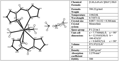 | ||
| Fig. 2 Molecular structure of the La–BTA complex and selected crystallographic data for the compound. | ||
Both BTA bidentate ligands in the complex are bound symmetrically to the La metal centre and are oriented in a planar fashion within the ligand and one to another. In addition to two BTA ligands, out of five La(III)-coordinated water molecules, four are located on the same side of the plane, formed by BTA ligands. The La–BTA complex is crystalized in its acidic form (La-containing moiety is negatively charged −1), accompanied by a single hydronium cation and two non-coordinated water molecules. Fourier-transform infrared spectroscopy FTIR of the La–BTA complex compared to the Ni–BTA complex and uncomplexed BTA is shown in Fig. S1.†
The preparation of the La–BTA complex (structure shown in Fig. 2) was scaled up to enable the production of grams of this precursor. Fig. S2† shows the XRD pattern of the powder recovered from the lab-scale La–BTA synthesis compared to the predicted XRD pattern simulated from the single crystal data (Material Studio, Biovia). The agreement between the experimental XRD and its predicted structure ensured that there was no significant structural change when the synthesis was scaled up. Both Ni–BTA and La–BTA complexes were found to be chemically stable under ambient conditions and were insensitive to mechanical impact and friction, increasing their appeal for large-scale applications.
Powders of Ni–BTA, La–BTA, and ammonium nitrate oxidant were mixed at a ratio of 3![[thin space (1/6-em)]](https://www.rsc.org/images/entities/char_2009.gif) :
:![[thin space (1/6-em)]](https://www.rsc.org/images/entities/char_2009.gif) 2
2![[thin space (1/6-em)]](https://www.rsc.org/images/entities/char_2009.gif) :
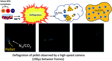
:![[thin space (1/6-em)]](https://www.rsc.org/images/entities/char_2009.gif) 10 and ground together in an agate mortar to obtain a homogeneous powder mixture. This mixture was then pressed into a pellet with a 13 mm die and at 100 kN force, using a hydraulic press. In all previous reports, BTA complexes were ignited under pressure by contact with an ignition wire in the absence of a solid oxidant, creating a slow-moving combustion wave-front. This method of combustion lead to different parts of the pellet igniting at different times and the formation of a monolithic foam.2 By contrast, we uniformly heated the entire pellet, containing a solid oxidant, until the point of combustion (e.g. without an ignition wire). It is important to note that this method is a hereto unexplored means of creating materials from BTA complexes. To accomplish this, the pellet was placed into a stainless-steel autoclave and heated in a furnace to 380 °C. We observed that when energetic pellets are ignited in air under these conditions, the pellet rapidly combusts, expelling gasses and catalyst nanoparticles.
10 and ground together in an agate mortar to obtain a homogeneous powder mixture. This mixture was then pressed into a pellet with a 13 mm die and at 100 kN force, using a hydraulic press. In all previous reports, BTA complexes were ignited under pressure by contact with an ignition wire in the absence of a solid oxidant, creating a slow-moving combustion wave-front. This method of combustion lead to different parts of the pellet igniting at different times and the formation of a monolithic foam.2 By contrast, we uniformly heated the entire pellet, containing a solid oxidant, until the point of combustion (e.g. without an ignition wire). It is important to note that this method is a hereto unexplored means of creating materials from BTA complexes. To accomplish this, the pellet was placed into a stainless-steel autoclave and heated in a furnace to 380 °C. We observed that when energetic pellets are ignited in air under these conditions, the pellet rapidly combusts, expelling gasses and catalyst nanoparticles.
After combustion, the autoclave was opened and only a black catalyst powder remained inside. The catalyst was cleaned of residual carbon by oxygen treatment at 400 °C for 4 hours. Fig. 3 shows the pressed pellet before deflagration, selected frames from a high-sped video taken during co-deflagration, and the final catalyst powder. The full high-speed Video clip is available online in the ESI section.†
Analysis of this high-speed video revealed that during the deflagration process, gas is being ejected from the pellet at approximately 10–20 m s−1 (confirming our postulation that this is a deflagration, and not a detonation process), and that the energetic components of the pellet are undergoing combustion simultaneously. In a typical experiment, a combined mass of Ni– and La–BTA complexes of 400 mg mixed at a 1![[thin space (1/6-em)]](https://www.rsc.org/images/entities/char_2009.gif) :
:![[thin space (1/6-em)]](https://www.rsc.org/images/entities/char_2009.gif) 2 ratio with ammonium nitrate oxidant yielded 130 mg of catalyst powder.
2 ratio with ammonium nitrate oxidant yielded 130 mg of catalyst powder.
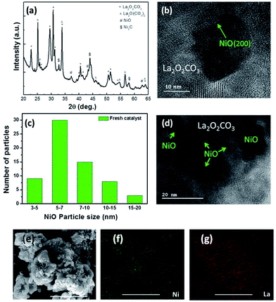
XRD of the cleaned catalyst in Fig. 4a reveals that the received catalyst is NiO supported on two different types of lanthanum oxycarbonate (PDF 00-048-1113 and PDF 00-032-0490). The formation of the oxycarbonate phases are intriguing because it may have been thought that upon deflagration, carbon in the BTA structure oxidizes to carbon dioxide and is expelled from the system along with nitrogen. Would this have been the case, we would have expected the support to be composed of lanthanum oxide (La2O3). The fact that the oxycarbonate phase is observed as the support means that CO2 generated during the combustion was incorporated into the solid structure, for example, via its reaction with La2O3 as shown in reaction (2).
| La2O3 + CO2 → La2O2CO3 | (2) |
DSC of the deflagrating pellet gave a peak temperature of 484.5 °C, sufficiently high to produce lanthanum oxycarbonate via this reaction.36
The in situ formation of the oxycarbonate phases proves to be advantageous for methane dry reforming, as it has been shown to keep the surface free of carbon accumulation during CH4 oxidation.33,37,38 XRD shows that the release of CO2 during deflagration also went to the formation of a small amount of nickel carbide. Fig. 4b shows a TEM image of a NiO nanoparticle imbedded in the oxycarbonate support. Lattice fringe measurements of the imbedded particle revealed the NiO(111) and NiO(200) planes confirming the phase identification as measured by XRD. Fig. 4c shows a histogram characterizing the size distribution of NiO particles created by the co-deflagration process. The average size was about 8 nm, while 10% were between 3–5 nm and 5% were between 15–20 nm.
The size distribution is visualized by a low-magnification TEM image shown in Fig. 4d. By comparison, SEM imaging in Fig. 4e shows that the size of the oxycarbonate support particles created during co-deflagration was microns in size. While individual NiO particles are not visible at this magnification, elemental mapping of Ni and La show their even distribution throughout the catalyst (Fig. 4f and g). It is important to point out that generating a supported catalyst using this novel co-deflagration technique is not necessarily the result one may have expected. The simultaneous energetic decomposition of Ni–BTA and La–BTA (which were only mixed mechanically) could have produced separated La2O3 and NiO particles with no interaction between them. Alternatively, Ni and La are known to form many stable mixed-metal oxides including LaNiO3, La2NiO4, LaNi2O4, and La3Ni2O7.39 What we found instead was that Ni-atoms crystallized independently from La (i.e. Ni–BTA deflagrated to form NiO and La–BTA deflagrated to form La2O2CO3); however, with significant interfacial interaction between them. While NiO crystalized into nanoparticles of 3–20 nm, the La2O2CO3 phase was nearly 10 times larger, thus giving rise to the supported Ni/La2O2CO3 structure.
A comparison of differential scanning calorimetry and thermogravimetric (DSC/TGA) curves for the BTA, Ni–BTA, and La–BTA and their mixtures is shown in Fig. 5.
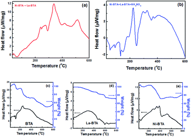 | ||
| Fig. 5 Differential scanning calorimetry (DSC) for Ni–BTA/La–BTA mixtures (a) without and (b) with ammonium nitrate. DSC/TGA curves for (c) neat BTA (d) La–BTA (e) Ni–BTA. | ||
We first see that the deflagration of Ni–BTA together with La–BTA closely approximates the superimposition of the DSC thermograms obtained when igniting the components independently. Introduction of ammonium nitrate to the pellet, however, changes the profile to contain several smaller exothermic peaks compared to one larger one. We note that the new La–BTA complex by itself involved the release of less heat over a wider range of temperatures and did not exhibit the characteristic sharp weight-loss feature associated with the rapid decomposition of the BTA molecule or the Ni–BTA complex.
We postulate that the slower rate of heat release from La–BTA relative to Ni–BTA could explain the difference in sizes of the received phases. Rapid crystallization processes, such as the one found during Ni–BTA decomposition, can tend towards the formation of smaller particles due to localized depletion.40 In such an instance, nucleation rather than growth is the predominant mechanism, and therefore many small NiO particles are formed. Furthermore, the fact that Ni nanoparticles appeared to crystallize faster than the La-based support means that NiO should be at least partially encapsulated (as seen in Fig. 4d), a phenomenon which was exploited to produce a stable catalyst.
The Ni dispersion was measured by reducing the catalyst in a 5% H2/N2 mixture and performing CO pulse titration. The dispersion of Ni was measured to be 5.6% and the average Ni crystal size using the same technique was calculated to be 10 nm, corroborating the results from TEM imaging. It is also of interest to note that TEM and XRD showed that the phases are characteristically crystalline in nature, even though it may have been thought that such a rapid synthesis would have led to amorphous products. While broadening is observed due to the small domain size, there is no indication that the catalyst contained amorphous material.
BET of the catalyst powder revealed that the fuel-to-oxidant ratio played a significant role controlling the structure of the catalyst (where the BTA complex is the fuel). Fuel-to-oxidant ratios of 2![[thin space (1/6-em)]](https://www.rsc.org/images/entities/char_2009.gif) :
:![[thin space (1/6-em)]](https://www.rsc.org/images/entities/char_2009.gif) 1, 1
1, 1![[thin space (1/6-em)]](https://www.rsc.org/images/entities/char_2009.gif) :
:![[thin space (1/6-em)]](https://www.rsc.org/images/entities/char_2009.gif) 1, and 1
1, and 1![[thin space (1/6-em)]](https://www.rsc.org/images/entities/char_2009.gif) :
:![[thin space (1/6-em)]](https://www.rsc.org/images/entities/char_2009.gif) 2 yielded catalyst powders with surface areas of 0.55, 9.96, and 20.39 m2 g−1, respectively. When the ratio between the BTA complexes and ammonium nitrate was further reduced to 1
2 yielded catalyst powders with surface areas of 0.55, 9.96, and 20.39 m2 g−1, respectively. When the ratio between the BTA complexes and ammonium nitrate was further reduced to 1![[thin space (1/6-em)]](https://www.rsc.org/images/entities/char_2009.gif) :
:![[thin space (1/6-em)]](https://www.rsc.org/images/entities/char_2009.gif) 5, the surface area of the catalyst dropped to 8.49 m2 g−1. We therefore only report catalytic results of the material prepared at a 1
5, the surface area of the catalyst dropped to 8.49 m2 g−1. We therefore only report catalytic results of the material prepared at a 1![[thin space (1/6-em)]](https://www.rsc.org/images/entities/char_2009.gif) :
:![[thin space (1/6-em)]](https://www.rsc.org/images/entities/char_2009.gif) 2 ratio. SEM images of the catalyst support at the above-mentioned fuel-oxidant ratios are shown in Fig. 6. While all materials were found to be porous microparticles, the 1
2 ratio. SEM images of the catalyst support at the above-mentioned fuel-oxidant ratios are shown in Fig. 6. While all materials were found to be porous microparticles, the 1![[thin space (1/6-em)]](https://www.rsc.org/images/entities/char_2009.gif) :
:![[thin space (1/6-em)]](https://www.rsc.org/images/entities/char_2009.gif) 2 fuel-to-oxidant ratio gave rise to a large number of porous nanoparticles. These results strongly indicate the feasibility of optimizing the catalyst structure by varying the ratios of the components in the energetic precursor.
2 fuel-to-oxidant ratio gave rise to a large number of porous nanoparticles. These results strongly indicate the feasibility of optimizing the catalyst structure by varying the ratios of the components in the energetic precursor.
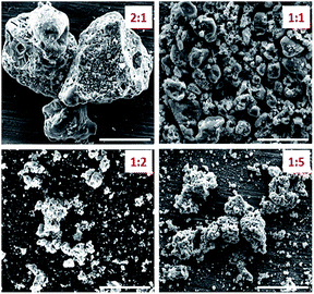 | ||
Fig. 6 SEM images of Ni/La2O2CO3 catalyst formed by co-deflagration where the fuel-to-oxidant ratio was varied from 2![[thin space (1/6-em)]](https://www.rsc.org/images/entities/char_2009.gif) : :![[thin space (1/6-em)]](https://www.rsc.org/images/entities/char_2009.gif) 1 until 1 1 until 1![[thin space (1/6-em)]](https://www.rsc.org/images/entities/char_2009.gif) : :![[thin space (1/6-em)]](https://www.rsc.org/images/entities/char_2009.gif) 5. Scale bar 5 μm. 5. Scale bar 5 μm. | ||
Temperature programmed reduction (TPR) of the fresh and oxidation is shown in Fig. S3.† NiO is reduced to Ni at 318 °C, indicative of its strong interaction with the support (weakly bound NiO nanoparticles are expected to undergo reduction at lower temperatures). The larger peak centred at 490 °C is the hydrogen-assisted decomposition of the oxycarbonate phase corroborated by thermographic analysis later in this report.
CO2-TPD in Fig. S4† indicates that there is a bimodal distribution of alkaline sites on the fresh catalyst. CO2 desorption at 140 °C and 340 °C represent CO2 desorption from weak and strong alkaline sites respectively. It is interesting to note that the area of the peak representing the strong alkaline-sites is larger than the one for weak-alkaline sites, a trait that is not always apparent even with classically basic supports based on Ca, Mg, and La.41 XPS of the Ni 3p electron in Fig. S5† indicate that the electronic nature of the NiO nanoparticles is nearly identical to NiO nanoparticles grown by exsolution, a route shown by us and other to produce strong catalyst–support interactions.30,33 XPS of the La 3d5/2 doublet associated with the La2O2CO3 is shown in Fig. S6.†
Catalytic activity of co-deflagrated Ni/La2O2CO3 catalysts
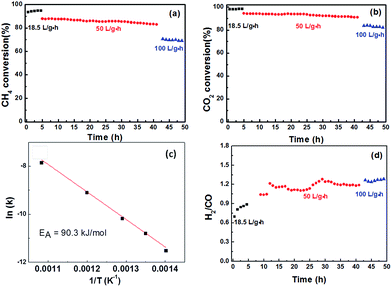
Fig. 7a and b shows the conversion of CH4 and CO2via methane dry reforming at 800 °C under various gas-hourly-space velocities (GHSVs). The CH4 and CO2 conversions at low space velocities (<20 L gcat−1 h−1) were compared to thermodynamic calculations predicting the maximum conversion by Gibbs free-energy minimization. Multiple models have been suggested that either take into account or ignore key carbon accumulation reactions, such as CH4 cracking and CO disproportionation. CH4 dry reforming catalysts which resisted carbon accumulation were expected to show a slightly lower CH4 conversion compared to those susceptible to coking. Xiao and co-workers modelled coke-free dry reforming catalyst and reported a maximum CH4 conversion at 800 °C to be approximately 91%,42 whereas Amin and co-workers reported that dry reforming catalysts susceptible to coking should expect a maximum conversion above 96%.43 In our system, at 18 L (gcat−1 h−1), we observed an initial CH4 conversion of 92%.The fact that the H2![[thin space (1/6-em)]](https://www.rsc.org/images/entities/char_2009.gif) :
:![[thin space (1/6-em)]](https://www.rsc.org/images/entities/char_2009.gif) CO products ratio was below 1 and the CO2 conversion was slightly higher than that of CH4 suggests that the reverse water–gas shift reaction, a side-reaction which consumes H2 and produces CO, is occurring simultaneously on the catalyst surface (reaction (3)).
CO products ratio was below 1 and the CO2 conversion was slightly higher than that of CH4 suggests that the reverse water–gas shift reaction, a side-reaction which consumes H2 and produces CO, is occurring simultaneously on the catalyst surface (reaction (3)).
| CO2 + H2 ⇌ CO + H2O | (3) |
A most remarkable feature of this new catalyst is that increasing the space velocity by more than 2.5 times, to 50 L (gcat−1 h−1), only caused a drop of a few percent in CH4 conversion. This observation suggests that there is only a small contribution of external mass transfer resistance in this space velocity range. The lack of internal mass transport limitation is supported by the calculated Weisz–Prater criteria for our catalyst, 0.09, well below the limit of 1.0 which would indicate an internal mass transport limitation. At a space velocity of 100 L gcat−1 h−1, the CH4 conversion was 71% and the products ratio remained the same as it was at 50 L (gcat−1 h−1), suggesting that the increased feed rate did not influence the ratio between dry reforming to the reverse water–gas shift reaction. Under this high space-velocity condition, the methane turnover frequency was calculated to be 76.5 s−1 based on molar consumption rate and the number of Ni active sites as determined by pulse CO titration.
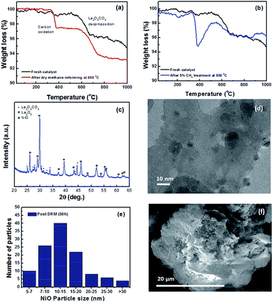
Additionally, the apparent activation energy for CH4, calculated from the Arrhenius plot in Fig. 7c, was 90.3 kJ mol−1, falling within the expected region of methane dry reforming catalysts.44 The stability of the catalyst was measured using TGA, XRD and TEM. Thermogravimetric analysis of fresh catalyst compared to catalyst that underwent dry reforming at 800 °C for 50 hours is shown in Fig. 8a. The weight loss observed in both the fresh and spent catalyst starting near 600 °C is due to the decomposition of the oxycarbonate phase and the formation of the lanthanum oxide phase (reverse of reaction (2)). Additionally, the spent catalyst showed an additional 2.8% weight loss attributed to carbon oxidation which accumulated on the surface. Such carbon accumulation is attributed to the decomposition of methane at high temperatures. To confirm this, the same catalyst was exposed to a 5% CH4/Ar mixture at 800 °C and subjected to the same TGA experiment as shown in Fig. 8b. Weight loss in the same temperature range provides strong evidence for the source of carbon accumulation in the dry reforming sample. The weight increase in Fig. 8b suggests is associated with Ni-carbides oxidizing to NiO. Such carbide formation is to be expected in a methane environment with no oxidizing agent. XRD in Fig. 8c shows that the catalyst support transformed into a mixture of La2O2CO3 and La2O3 after 50 hours of dry reforming. The fact that La2O3 is the dominant species after dry reforming, with only small amounts of lanthanum oxycarbonate remaining, support the fact that the Ni dispersion is sufficiently high and that the oxycarbonate phase is actively maintaining a coke-free surface by gasifying accumulated carbon to CO.45Fig. 8d shows a characteristic TEM micrograph of the catalyst after 50 hours of methane dry reforming. We find that there is no sign of multi-walled carbon nanotubes (MWCNT) or graphitic carbon on the surface. Such a mechanism proceeds when the Ni particle is lifted off of the support surface by a growing carbon nanotube. After dislodging, MWCNT growth can block active sites and clog pores, diminishing the catalyst activity. Owing to the fact that the NiO particles are partially encapsulated by the La2O2CO3 support after co-deflagration, the interaction between the catalyst and the support is enhanced, and strong enough to block the tip-growth mechanism from the formation of MWCNTs.13 As a result, we maintain a clean and active surface throughout the reaction.
Furthermore, the surface is kept clean from graphitic carbon growth via the base-growth mechanism owing to the presence of the oxycarbonate phase. Analysis of TEM images after dry methane reforming shows that the average NiO particle size increased by 5 nm compared to the fresh catalyst, and that about 5% of the particles grew to over 30 nm. This is likely due to the fact that not every NiO particle was equally well attached to the support. The NiO particles which were more weakly attached were able to diffuse and sinter during the catalytic process, leading to a small increase in the average particle size. SEM imaging of the spent catalyst in Fig. 8f also confirms that there is no MWCNT growth on the sample. Further TEM evidence of catalyst cleanliness post reaction can be found in Fig. S7.†
Finally, the stability of our catalyst was measured conditions resembling those used in industry by using a 50 mm OD ceramic tube reactor in a vertical packed-bed configuration containing 1 g of catalyst. Fig. 9 shows the product ratio and methane conversion at 800 °C and a 50L h−1 feed of equimolar CH4![[thin space (1/6-em)]](https://www.rsc.org/images/entities/char_2009.gif) :
:![[thin space (1/6-em)]](https://www.rsc.org/images/entities/char_2009.gif) CO2 during a “moisture swing” using a heated water injection. During this swing, the molar flow of water was 10% compared to the molar flow of methane at the inlet. The injection of moisture led to a relatively stable methane conversion level accompanied by an expected increase of a few percent in the H2
CO2 during a “moisture swing” using a heated water injection. During this swing, the molar flow of water was 10% compared to the molar flow of methane at the inlet. The injection of moisture led to a relatively stable methane conversion level accompanied by an expected increase of a few percent in the H2![[thin space (1/6-em)]](https://www.rsc.org/images/entities/char_2009.gif) :
:![[thin space (1/6-em)]](https://www.rsc.org/images/entities/char_2009.gif) CO product ratio. Such an increase in H2 production is expected since the water injection enables methane steam reforming, which ideally produces H2
CO product ratio. Such an increase in H2 production is expected since the water injection enables methane steam reforming, which ideally produces H2![[thin space (1/6-em)]](https://www.rsc.org/images/entities/char_2009.gif) :
:![[thin space (1/6-em)]](https://www.rsc.org/images/entities/char_2009.gif) CO which is 3 times larger compared to dry reforming.
CO which is 3 times larger compared to dry reforming.
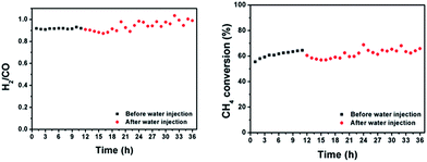 | ||
| Fig. 9 Product ratio and methane conversion of atmospheric dry reforming over co-deflagrated Ni/La2O2CO3 under conditions where steam is injected at a molar flow rate 10% that of methane. | ||
Conclusions
In this work, we present a series of innovations with the goal of creating highly-active and stable supported nanocatalyst for CH4 dry reforming. Most importantly, a new methodology for the synthesis of a superior version of the Ni/La2O2CO3 catalyst was achieved by exploiting the energy provided to atoms during the deflagration of high-nitrogen energetic materials. This result was unprecedented because the simultaneous deflagration of Ni–BTA and La–BTA could have instead produced non-catalytic materials such as a separated La2O3 and NiO particles with no interaction between them, or any number of mixed-metal oxides. Additionally, CO2 generated during the deflagration process was incorporated into the support structure through the creation of the oxycarbonate phase. We also demonstrated that the structure of the catalysts can be modulated by varying the ratio of components in the deflagratable pellet. In our experiments Ni/La2O2CO3 synthesized by this method showed high activity towards CH4 dry reforming for 50 hours, even at high space velocities (100 L gcat−1 h−1). Importantly, the stability of the catalyst showed only minimal carbon accumulation, and particle sintering. The synthesis of a new La–BTA complex served as the enabling material for the preparation of the above-mentioned catalyst. Since supported catalysts are found ubiquitously in industry, co-deflagration represents a novel method for synthesizing stable supported catalysts and can be widely applied for the creation of future energy storage and conversion technologies.Conflicts of interest
All authors except for S. L, S. P, and H. H have filed a patent for the catalyst technology in this article.Acknowledgements
The authors acknowledge partial funding of this project by the Technology Innovation Momentum Fund (Israel) Limited Partnership c/o Ramot at Tel-Aviv University.References
- M. Talawar, R. Sivabalan, T. Mukundan, H. Muthurajan, A. Sikder, B. Gandhe and A. S. Rao, Environmentally compatible next generation green energetic materials (GEMs), J. Hazard. Mater., 2009, 161, 589–607 CrossRef CAS.
- B. C. Tappan, S. A. Steiner III and E. P. Luther, Nanoporous metal foams, Angew. Chem., Int. Ed., 2010, 49, 4544–4565 CrossRef CAS.
- A. H. Mueller, B. C. Tappan, E. P. Luther and A. K. Burrell, Nanostructured Electrodes for Photochemical Hydrogen Generation, ECS Trans., 2009, 19, 9–15 CAS.
- B. Qu, X. Lu, Y. Wu, X. You and X. Xu, Synthesis of copper micro-rods with layered nano-structure by thermal decomposition of the coordination complex Cu(BTA)2, Nanoscale Res. Lett., 2015, 10, 42 CrossRef.
- P. J. Eulgem, A. Klein, N. Maggiarosa, D. Naumann and R. W. Pohl, New Rare Earth Metal Complexes with Nitrogen-Rich Ligands: 5, 5′-Bitetrazolate and 1,3-Bis (tetrazol-5-yl) triazenate—On the Borderline between Coordination and the Formation of Salt-Like Compounds, Chem.–Eur. J., 2008, 14, 3727–3736 CrossRef CAS.
- A. Hammerl, G. Holl, T. M. Klapötke, P. Mayer, H. Nöth, H. Piotrowski and M. Warchhold, Salts of 5,5′-Azotetrazolate, Eur. J. Inorg. Chem., 2002, 2002, 834–845 CrossRef.
- C.-F. Qiao, Q. Wei, Z.-Q. Xia, C.-S. Zhou and S.-P. Chen, The effect of water molecule on the thermal stability of lanthanide compounds with 1,3-benzeneditetrazol-5-yl, J. Therm. Anal. Calorim., 2012, 107, 527–533 CrossRef CAS.
- J.-M. Lin, Y.-F. Guan, D.-Y. Wang, W. Dong, X.-T. Wang and S. Gao, Syntheses, structures and properties of seven isomorphous 1D Ln3+ complexes Ln(BTA)(HCOO)(H2O)3 (H2BTA = bis (tetrazoly) amine, Ln = Pr, Gd, Eu, Tb, Dy, Er, Yb) and two 3D Ln3+ complexes Ln(HCOO)3 (Ln = Pr, Nd), Dalton Trans., 2008, 6165–6169 RSC.
- D. Pakhare and J. Spivey, A review of dry (CO2) reforming of methane over noble metal catalysts, Chem. Soc. Rev., 2014, 43, 7813–7837 RSC.
- A. W. Budiman, S.-H. Song, T.-S. Chang, C.-H. Shin and M.-J. Choi, Dry reforming of methane over cobalt catalysts: a literature review of catalyst development, Catal. Surv. Asia, 2012, 16, 183–197 CrossRef CAS.
- J. Guo, H. Lou, H. Zhao, D. Chai and X. Zheng, Dry reforming of methane over nickel catalysts supported on magnesium aluminate spinels, Appl. Catal., A, 2004, 273, 75–82 CrossRef CAS.
- J. M. Ginsburg, J. Piña, T. El Solh and H. I. De Lasa, Coke formation over a nickel catalyst under methane dry reforming conditions: thermodynamic and kinetic models, Ind. Eng. Chem. Res., 2005, 44, 4846–4854 CrossRef CAS.
- B. A. Rosen and S. Singh, Fossil Fuels: Coke-Resistant Nanomaterials for Gas-to-Liquid (GTL) Fuels, Nanotechnol. Energy Sustainability, 2017, 59–82 CAS.
- B. Klingenberg and M. A. Vannice, Influence of pretreatment on lanthanum nitrate, carbonate, and oxide powders, Chem. Mater., 1996, 8, 2755–2768 CrossRef CAS.
- A. E. Awadallah, S. M. Solyman, A. A. Aboul-Enein, H. A. Ahmed, N. A. Aboul-Gheit and S. A. Hassan, Effect of combining Al, Mg, Ce or La oxides to extracted rice husk nanosilica on the catalytic performance of NiO during COx-free hydrogen production via methane decomposition, Int. J. Hydrogen Energy, 2017, 42, 9858–9872 CrossRef CAS.
- N. Charisiou, G. Siakavelas, K. Papageridis, A. Baklavaridis, L. Tzounis, D. Avraam and M. Goula, Syngas production via the biogas dry reforming reaction over nickel supported on modified with CeO2 and/or La2O3 alumina catalysts, J. Nat. Gas Sci. Eng., 2016, 31, 164–183 CrossRef CAS.
- N. Charisiou, G. Siakavelas, K. Papageridis, A. Baklavaridis, L. Tzounis, K. Polychronopoulou and M. Goula, Hydrogen production via the glycerol steam reforming reaction over nickel supported on alumina and lanthana–alumina catalysts, Int. J. Hydrogen Energy, 2017, 42, 13039–13060 CrossRef CAS.
- N. Charisiou, G. Siakavelas, L. Tzounis, V. Sebastian, A. Monzon, M. Baker, S. Hinder, K. Polychronopoulou, I. Yentekakis and M. Goula, An in depth investigation of deactivation through carbon formation during the biogas dry reforming reaction for Ni supported on modified with CeO2 and La2O3 zirconia catalysts, Int. J. Hydrogen Energy, 2018, 43, 18955–18976 CrossRef CAS.
- N. Charisiou, L. Tzounis, V. Sebastian, S. Hinder, M. Baker, K. Polychronopoulou and M. Goula, Investigating the correlation between deactivation and the carbon deposited on the surface of Ni/Al2O3 and Ni/La2O3–Al2O3 catalysts during the biogas reforming reaction, Appl. Surf. Sci., 2018 DOI:10.1016/j.apsusc.2018.05.177.
- H. Cheng, G. Li, H. Zhao, X. Lu, Q. Xu and W. Tao, Effects of preparation technique and lanthana doping on Ni/La2O3–ZrO2 catalysts for hydrogen production by CO2 reforming of coke oven gas, Catal. Today, 2017, 23–31 CAS.
- A. H. Fakeeha, W. U. Khan, A. S. Al-Fatesh, A. A. Ibrahim and A. E. Abasaeed, Production of hydrogen from methane over lanthanum supported bimetallic catalysts, Int. J. Hydrogen Energy, 2016, 41, 8193–8198 CrossRef CAS.
- D. Gong, S. Li, S. Guo, H. Tang, H. Wang and Y. Liu, Lanthanum and cerium co-modified Ni/SiO2 catalyst for CO methanation from syngas, Appl. Surf. Sci., 2018, 434, 351–364 CrossRef CAS.
- W. U. Khan, A. H. Fakeeha, A. S. Al-Fatesh, A. A. Ibrahim and A. E. Abasaeed, La2O3 supported bimetallic catalysts for the production of hydrogen and carbon nanomaterials from methane, Int. J. Hydrogen Energy, 2016, 41, 976–983 CrossRef.
- H. Ma, L. Zeng, H. Tian, D. Li, X. Wang, X. Li and J. Gong, Efficient hydrogen production from ethanol steam reforming over La-modified ordered mesoporous Ni-based catalysts, Appl. Catal., B, 2016, 181, 321–331 CrossRef CAS.
- L. Pino, C. Italiano, A. Vita, M. Laganà and V. Recupero, Ce0.70La0.20Ni0.10O2−δ catalyst for methane dry reforming: influence of reduction temperature on the catalytic activity and stability, Appl. Catal., B, 2017, 218, 779–792 CrossRef CAS.
- M. Pudukudy, Z. Yaakob and M. S. Takriff, Methane decomposition over Pd promoted Ni/MgAl2O4 catalysts for the production of COx free hydrogen and multiwalled carbon nanotubes, Appl. Surf. Sci., 2015, 356, 1320–1326 CrossRef CAS.
- A. Quindimil, U. De-La-Torre, B. Pereda-Ayo, J. A. González-Marcos and J. R. González-Velasco, Ni catalysts with La as promoter supported over Y-and BETA-zeolites for CO2 methanation, Appl. Catal., B, 2018, 238, 393–403 CrossRef CAS.
- A. Tsoukalou, Q. Imtiaz, S. M. Kim, P. M. Abdala, S. Yoon and C. R. Müller, Dry-reforming of methane over bimetallic Ni–M/La2O3 (M = Co, Fe): The effect of the rate of La2O2CO3 formation and phase stability on the catalytic activity and stability, J. Catal., 2016, 343, 208–214 CrossRef CAS.
- D. Wierzbicki, M. Motak, T. Grzybek, M. E. Gálvez and P. Da Costa, The influence of lanthanum incorporation method on the performance of nickel-containing hydrotalcite-derived catalysts in CO2 methanation reaction, Catal. Today, 2018, 307, 205–211 CrossRef CAS.
- D. Neagu, T.-S. Oh, D. N. Miller, H. Ménard, S. M. Bukhari, S. R. Gamble, R. J. Gorte, J. M. Vohs and J. T. Irvine, Nano-socketed nickel particles with enhanced coking resistance grown in situ by redox exsolution, Nat. Commun., 2015, 6, 8120 CrossRef.
- T. Xie, L. Shi, J. Zhang and D. Zhang, Immobilizing Ni nanoparticles to mesoporous silica with size and location control via a polyol-assisted route for coking-and sintering-resistant dry reforming of methane, Chem. Commun., 2014, 50, 7250–7253 RSC.
- M. Ocsachoque, F. Pompeo and G. Gonzalez, Rh–Ni/CeO2–Al2O3 catalysts for methane dry reforming, Catal. Today, 2011, 172, 226–231 CrossRef CAS.
- S. Singh, D. Zubenko and B. A. Rosen, Influence of LaNiO3 shape on its solid-phase crystallization into coke-free reforming catalysts, ACS Catal., 2016, 6, 4199–4205 CrossRef CAS.
- J. P. Wang, W. B. Yi and C. Cai, An improved method for the preparation of energetic aminotetrazolium salts, Z. Anorg. Allg. Chem., 2012, 638, 53–55 CrossRef CAS.
- A. Pazik and A. Skwierawska, Synthesis and spectroscopic properties of new bis-tetrazoles, J. Inclusion Phenom. Macrocyclic Chem., 2013, 77, 83–94 CrossRef CAS.
- B. Bakiz, F. Guinneton, M. Arab, A. Benlhachemi, S. Villain, P. Satre and J.-R. Gavarri, Carbonatation and decarbonatation kinetics in the La2O3–La2O2CO3 system under CO2 gas flows, Adv. Mater. Sci. Eng., 2010, 2010, 360597 Search PubMed.
- J. F. Múnera, S. Irusta, L. M. Cornaglia, E. A. Lombardo, D. V. Cesar and M. Schmal, Kinetics and reaction pathway of the CO2 reforming of methane on Rh supported on lanthanum-based solid, J. Catal., 2007, 245, 25–34 CrossRef.
- D. Zubenko, S. Singh and B. A. Rosen, Exsolution of Re-alloy catalysts with enhanced stability for methane dry reforming, Appl. Catal., B, 2017, 209, 711–719 CrossRef CAS.
- M. Crespin, P. Levitz and L. Gatineau, Reduced forms of LaNiO3 perovskite. Part 1—Evidence for new phases: La2Ni2O5 and LaNiO2, J. Chem. Soc., Faraday Trans. 2, 1983, 79, 1181–1194 RSC.
- A. S. Karas, J. Glaser and S. C. Glotzer, Using depletion to control colloidal crystal assemblies of hard cuboctahedra, Soft Matter, 2016, 12, 5199–5204 RSC.
- G. d. Souza, N. R. Marcilio and O. W. Perez-Lopez, Dry reforming of methane at moderate temperatures over modified Co–Al Co-precipitated catalysts, Mater. Res., 2014, 17, 1047–1055 CrossRef.
- Y. Li, B. Jin and R. Xiao, Carbon dioxide reforming of methane with a free energy minimization approach, Korean J. Chem. Eng., 2007, 24, 688–692 CrossRef CAS.
- M. K. Nikoo and N. Amin, Thermodynamic analysis of carbon dioxide reforming of methane in view of solid carbon formation, Fuel Process. Technol., 2011, 92, 678–691 CrossRef CAS.
- M. Bradford and M. Vannice, CO2 reforming of CH4, Catal. Rev., 1999, 41, 1–42 CrossRef CAS.
- X. Li, D. Li, H. Tian, L. Zeng, Z.-J. Zhao and J. Gong, Dry reforming of methane over Ni/La2O3 nanorod catalysts with stabilized Ni nanoparticles, Appl. Catal., B, 2017, 202, 683–694 CrossRef CAS.
Footnotes |
| † Electronic supplementary information (ESI) available: Powder XRD simulations from single crystal data along with high speed video of the co-deflagration process. CCDC 1577737. For ESI and crystallographic data in CIF or other electronic format see DOI: 10.1039/c8ta08343f |
| ‡ Authors with equal contribution. |
| This journal is © The Royal Society of Chemistry 2019 |


