
 Open Access Article
 This Open Access Article is licensed under a Creative Commons Attribution-Non Commercial 3.0 Unported Licence
Electrochemical characterization of the stimuli-response of surface-immobilized elastin-like polymers†
Marissa A.
Morales
 a,
Wynter A.
Paiva
b,
Laura
Marvin
b,
Eva Rose M.
Balog
b and
Jeffrey Mark
Halpern
*a
a,
Wynter A.
Paiva
b,
Laura
Marvin
b,
Eva Rose M.
Balog
b and
Jeffrey Mark
Halpern
*a
aDepartment of Chemical Engineering, University of New Hampshire, Durham, NH, USA. E-mail: Jeffrey.halpern@unh.edu
bDepartment of Chemistry and Physics, University of New England, Biddeford, ME, USA
First published on 29th October 2019
Abstract
Elastin-like polymers (ELPs) are frequently used in a variety of bioengineering applications because of their stimuli-responsive properties. Above their transition temperature, ELPs will adopt different structures that promote intra- and intermolecular hydrophobic contacts to minimize unfavorable interactions with an aqueous environment. We electrochemically characterize the stimuli-responsive behavior of surface-immobilized ELPs corresponding to two proposed states: extended and collapsed. In the extended state the ELPs are more solvated. In the collapsed state, triggered by introducing an environmental stimulus, non-polar intramolecular contacts within ELPs are favored, resulting in quantifiable morphological changes on the surface characterized using electrochemical impedance spectroscopy (EIS). Charge transfer resistance, a component of impedance, was shown to increase after exposing an ELP modified electrode to a high salt concentration environment (3.0 M NaCl). An increase in charge transfer resistance indicates an increase in the insulating layer on the electrode surface consistent with the proposed mechanism of collapse, as the ELPs have undergone morphological changes to hinder the kinetics of the redox couple exchange. Further characterization of the surface-immobilized ELPs showed a reproducible surface modification, as well as reversibility and tunability of the stimuli-response.
Introduction
Elastin-like polymers (ELPs) are a class of intrinsically disordered polymers sharing a common pentapeptide repeat [VPGXG] (V = valine, P = proline, G = glycine, and X = guest residue).1,2 ELPs have a dynamic structure, adopting environment dependent conformations and interactions resulting in what is described as the stimuli-response of ELPs.3–6 Below their transition temperature, ELPs are soluble; at temperatures above their transition temperature, ELPs begin to aggregate forming intermolecular and intramolecular contacts between their non-polar regions to minimize unfavourable interactions with the environment.7The stimuli-response of ELPs is dictated by the hydrophobicity of the ELP; the more hydrophobic the ELP, the lower the transition temperature. The hydrophobicity is predominately influenced by guest residue identity and overall ELP length, which allows for the design of ELPs to desired transition temperatures and stimuli-responsive properties for specific applications.8,9 In addition, the environmental conditions, such as pH, ionic strength, and ELP concentration, can also influence the transition temperature creating unique stimuli-response profiles.7,10 Therefore, ELPs are interesting candidates for a variety of bioengineering applications. For example, ELP nano- and micro-assemblies have been developed for advanced drug delivery applications such as targeted delivery of chemotherapeutics.11–14 ELPs have also been incorporated into hydrogels for applications such as tissue engineering, wound healing, and optically-active materials.15–18 Currently, the broad scope of research applications using ELPs is, in part, facilitated by the robust preliminary characterization of physical properties and behaviour of ELPs in solution.19–23
Surface-immobilized ELPs will operate differently than solution-based ELPs. In solution, ELPs are free to move within a 3D space, allowing for ELP aggregation to minimize interactions between the non-polar regions of ELPs and their environment. However, with ELPs tethered on a surface, the ELPs movement is restricted, with the extreme case being that only intramolecular extension and collapse is available to each polymer (Fig. 1). In the extended state the ELPs are more solvated. In the collapsed state, triggered by introducing an environmental stimulus, non-polar intramolecular contacts within ELPs are favoured, resulting in quantifiable morphological changes on the surface.
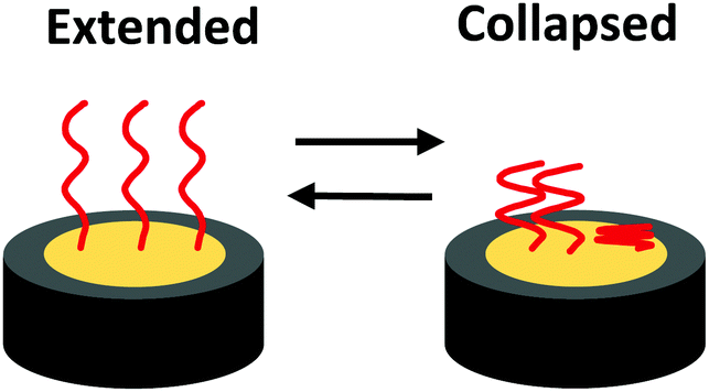 | ||
| Fig. 1 Proposed model of the extended state and collapsed state of surface-immobilized ELPs. | ||
Previous research of the stimuli-response of surface-immobilized ELPs has demonstrated their ability to generate dynamic “smart” surfaces, modulating the surface properties through exposure to different environmental stimuli. Dynamic ELP surfaces have shown potential in a variety of bioengineering applications, predominantly as biosensor or chemical sensor platforms.24,25 A major benefit of the stimuli-responsive properties of ELP surfaces is the ability to regenerate the sensor surface by modulating the ELPs extension or collapse through the environmental conditions allowing for reuse.26 The capture and release of specific analytes have been demonstrated using ELP fusion proteins as well as non-specific interactions with other hydrophobic analytes.27 However, the potential applications of these technologies are limited due to the analytical techniques used. For example, changes in surface morphology due to the stimuli-response of surface-bound ELPs have been characterized using microcantilever systems. The previous model, from microcantilever systems, included extension and collapse of ELP.28 However, microcantilever systems require expensive instrumentation for analysis and a skilled operator, hindering point-of-care applications.24,28
Instead, to promote point-of-care use, we undertook the characterization of the stimuli-response of surface-immobilized ELPs using electrochemical impedance spectroscopy (EIS). EIS was used to record the impedance response from an ELP modified electrode by quantifying the resistance to the flow of electrons of the redox couple at the electrode surface under an applied alternating voltage potential. An increase of impedance is expected in the collapsed state compared to the extended state. We propose that the collapsed state of the ELPs hinders the kinetics of the redox couple exchange by decreasing the available surface area for exchange while simultaneously creating more complex diffusion pathways at the electrode surface. Within this work we demonstrated reproducibility of an ELP surface modification, further characterization of the ELP modified surface demonstrating reversibility and tunability in the stimuli-response, and previously unreported intermediate states. The robust electrochemical characterization of a stimuli-responsive ELP modified surface lays the foundation for future electrochemical sensor applications.
Experimental
Elastin-like polymer synthesis
The I40 polymer was designed and synthesized as previously described.29 Briefly, the plasmid POE-W I40 was transformed into BL21(DE3) E. coli and plated on 2 × YT solid medium + carbenicillin. Starter cultures of nutrient-rich liquid medium + carbenicillin were inoculated with multiple colonies and shaken at 200 rpm at 37 °C for 2–4 hours until visible growth was detected. Cultures were transferred to 1 L volumes of the same media in 2 L flasks, which were then shaken at 200 rpm at 37 °C for 24 hours. Cells were harvested by centrifugation, and I40 was purified from the periplasmic fraction using inverse transition cycling.30 Purified I40 was lyophilized for long-term storage at −20 °C. Our full protocol used in the expression and purification of I40 is available on protocols.io (https://dx.doi.org/10.17504/protocols.io.vfce3iw).A second polymer, I40-Blocked, was synthesized by alkylation of the thiol-containing cysteine residue of I40. Purified I40 was resuspended to a concentration of 0.2 mM in 1 mL of sterile-filtered 6 M guanidine HCl. Dithiothreitol (DTT) was added to a concentration of 10 mM and the solution was mixed and incubated for 10 min. Iodoacetamide was added to a final concentration of 25 mM. The solution was mixed and placed in the dark for 30 min. The reaction was then quenched with an additional 20 mM DTT. Alkylated I40 was dialyzed into deionized (DI) water overnight at 4 °C and lyophilized.
Elastin-like polymer surface immobilization
ELPs were immobilized on gold via the thiol on the cysteine residue of I40, taking advantage of the well characterized thiol–gold interaction.31–33 Prior to modification with either the I40 or I40-Blocked polymer, the gold electrode was polished with 3 μM diamond slurry followed by 1 μM diamond slurry rinsing with methanol and deionized (DI) water (Milli-Q D3). A final polish was done with 0.55 μM alumina slurry. The electrode was rinsed thoroughly (∼30 seconds) with DI water before immersing in a pre-chilled polymer solution at a concentration of 0.0125 mg mL−1 in 3.5 mM tris(2-carboxyethyl)phosphine (TCEP) pH 7.4 for 30 minutes at T = 4 °C. The modified electrode was rinsed thoroughly with DI water and immediately transferred to the redox couple solution to measure the impedance response.Electrochemical impedance spectroscopy
All electrochemistry was performed at the open circuit potential in a Gamry Instruments VistaShield Faraday cage with a Gamry Instruments 600+ Potentiostat/Galvanostat/ZRA over a frequency range of 100![[thin space (1/6-em)]](https://www.rsc.org/images/entities/char_2009.gif) 000 Hz to 0.05 Hz with an AC voltage potential of 10 mVRMS. A three-electrode array was used comprised of a platinum wire counter electrode, Ag/AgCl reference electrode, and a gold working electrode (BASi, 1.6 mm rod electrode) modified with ELPs. To measure the impedance response, the ELP modified gold electrode was removed from the test solution and transferred into a 10 mM [Fe(CN)6]3−/4− redox couple solution at room temperature to generate the flow of electrons at the electrode. Prior to recording the impedance response, high-purity nitrogen was bubbled through the 10 mM [Fe(CN)6]3−/4− redox couple solution for 10 minutes to purge the system of any oxidative species. The impedance response was analysed using Gamry EChem Analyst software.
000 Hz to 0.05 Hz with an AC voltage potential of 10 mVRMS. A three-electrode array was used comprised of a platinum wire counter electrode, Ag/AgCl reference electrode, and a gold working electrode (BASi, 1.6 mm rod electrode) modified with ELPs. To measure the impedance response, the ELP modified gold electrode was removed from the test solution and transferred into a 10 mM [Fe(CN)6]3−/4− redox couple solution at room temperature to generate the flow of electrons at the electrode. Prior to recording the impedance response, high-purity nitrogen was bubbled through the 10 mM [Fe(CN)6]3−/4− redox couple solution for 10 minutes to purge the system of any oxidative species. The impedance response was analysed using Gamry EChem Analyst software.
The stimuli-response of I40 and I40-Blocked modified electrodes was characterized by recording the impedance response in a 10 mM [Fe(CN)6]3−/4− solution after exposing the electrode to a high salt concentration environment (3.0 M NaCl) for 2 hours or to a no salt environment (0.0 M NaCl) overnight at room temperature. 0.0 M NaCl soaks were in DI water with no additives.
Atomic force microscopy
The I40 modified gold surfaces were characterized using atomic force microscopy (AFM) with an Asylum Cypher ES scanning probe microscope. Imaging was performed at temperature T = 25 °C using AC mode in DI water using a BudgetSensors SHR150 probe driven with blueDrive photothermal excitation. A scan rate of 0.70 Hz with a 5 μm × 5 μm scan size was used to produce 1024 pixels × 1024 pixels images.Results and discussion
I40 polymer construct information
The core structure of our ELP consists of 40 repeats of the pentapeptide VPGIG (Fig. 2). The I40 polymer was also designed to contain a cysteine residue at the N-terminus for immobilization of I40 on the electrode surface. This composition confers to the polymer the ability to undergo well-characterized salt- and temperature-driven contraction in an experimentally convenient range of temperatures and polymer concentrations.34 The polymer size and purity were confirmed by SDS-PAGE; results are available in the ESI† (Fig. S1). The stimuli-responsive behaviour of I40 was previously validated and published.29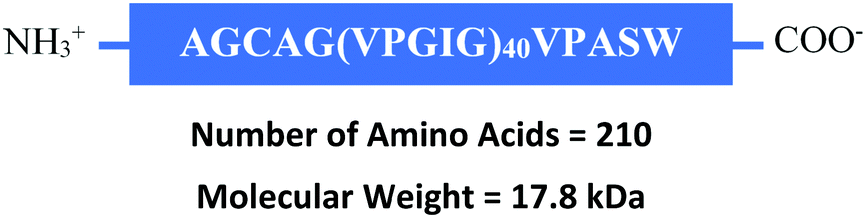 | ||
| Fig. 2 Complete amino acid sequence of I40. I40-Blocked has the same sequence with the expectation of the modified cysteine residue. | ||
Thiol chemistry was used to form a bond between the sulphur of the cysteine on I40 and the gold electrode surface.31–33 The I40-Blocked polymer, containing a modified cysteine residue, was used as a comparison to I40 to validate the thiol interaction with the gold surface. Alkylation of the cysteine residue was verified by reacting I40-Blocked with Ellman's Reagent (5′5′-dithiobis-(2-nitrobenzoic acid)) to measure the thiol content of the polymer after alkylation.35,36 Results are available in the ESI† (Fig. S2).
Elastin-like polymer surface immobilization
The impedance data obtained after ELP immobilization on a gold electrode was graphed using a Nyquist plot of the imaginary impedance vs. real impedance. A Randle's circuit with a constant phase element was used to interpret the impedance data by calculating the charge transfer resistance along with other components of the impedance response (Fig. 3). Charge transfer resistance (Rct) was used to compare the impedance response of unmodified, I40 modified, and I40-Blocked modified electrodes. Charge transfer resistance (Rct) is correlated to the diameter of the semi-circular region of the Nyquist curve; larger diameters represent higher charge transfer resistance values. Residuals of the impedance fit are available in the ESI† (Fig. S3 and S4); fitting error is provided in the figure of Nyquist curves (Fig. 4). | ||
| Fig. 3 Randle's circuit is used to interpret impedance data comprised of solution resistance (Rs), charge transfer resistance (Rct), Warburg impedance (W), and double-layer capacitance (Cdl). | ||
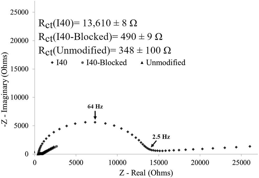 | ||
| Fig. 4 Impedance response shows a significant increase in charge transfer resistance for the I40 modified electrode, which is absent on the I40-Blocked modified. The increase in charge transfer resistance indicates a strong attachment of I40 to the surface. The error presented is the fit error. | ||
An increase in charge transfer resistance was expected after gold electrode modification, an expected result from the insulating layer formed by the polymer on the electrode surface which hinders the kinetics of the redox couple exchange. The impedance response for an unmodified electrode was compared to that of an electrode modified with either I40 or I40-Blocked (Fig. 4). Charge transfer resistance values for each electrode are included in the figure, with the fit error. Residual curves and goodness of fit calculations were reviewed to ensure an accurate equivalent circuit model was used. Sample residual curves can be found in the ESI† (Fig. S3 and S4).
The impedance response of an unmodified electrode showed minimal charge transfer resistance with a Warburg impedance tail extending at ∼45° observed on the Nyquist plot, indicating semi-infinite diffusion of the redox couple to the electrode surface unrestricted by any surface features. The observed impedance response of the unmodified electrode can be described as a purely mass transfer limited process.
As an experimental example of a single I40 modified electrode, Fig. 4 shows a significant increase in charge transfer resistance of 13.6 kΩ compared to an unmodified gold electrode, shown graphically by the increase in semi-circle diameter of the Nyquist plot. The increase in charge transfer resistance on the I40 modified electrode compared to an unmodified electrode was caused by the formation of an insulating layer on the electrode surface validating the presence of I40 on the electrode after modification.
Evaluation of the reproducibility of a surface modification is important to ensure a consistent and reliable response in subsequent characterization steps.37 Reproducibility of the I40 surface modification was evaluated by comparing the impedance response across multiple unique modification events (N = 6) (Fig. 5). An average charge transfer resistance of 12.7 ± 1.4 kΩ is reported, demonstrating sufficient agreement in the impedance response observed across the different electrodes. Agreement in the impedance responses obtained across the different electrodes indicated consistent electrode coverage by the I40 layer formed on the surface from each unique modification event. Calculated charge transfer resistance values for each electrode, with fitting error, are included in the ESI† (Table S1).
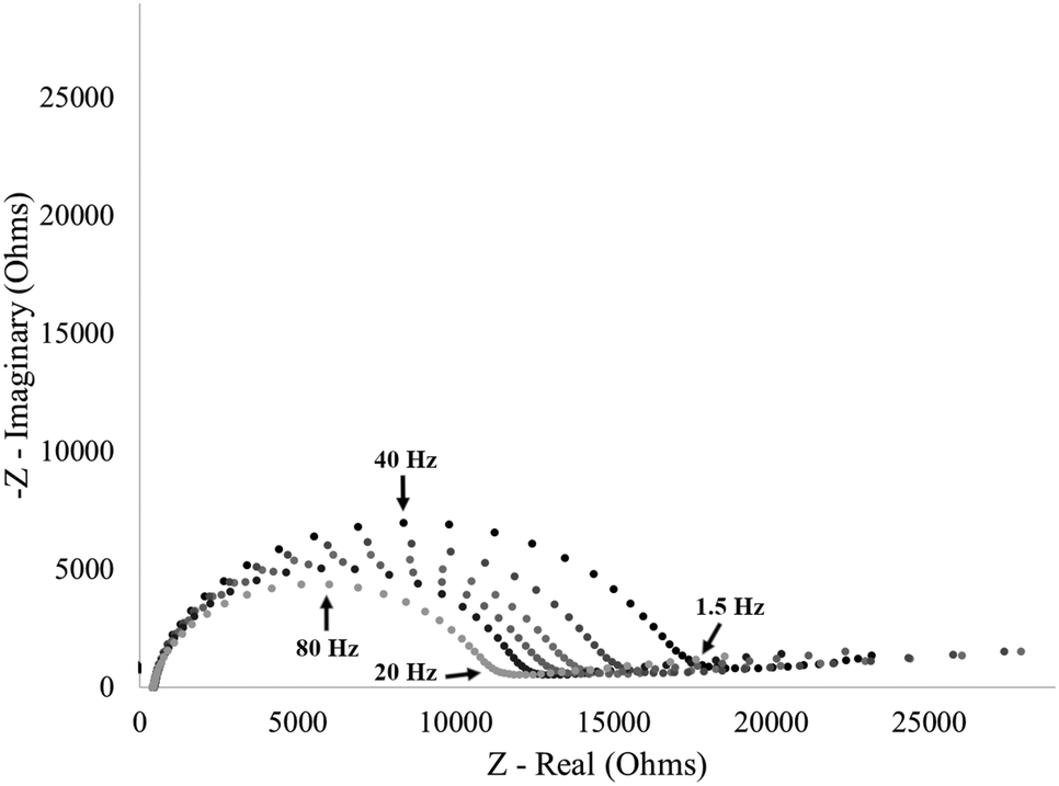 | ||
| Fig. 5 Impedance response from six unique modification events with I40 with an average charge transfer resistance of 12.7 ± 1.4 kΩ. Calculated charge transfer resistance values for each electrode are included in the ESI† (Table S1). | ||
The impedance response of an I40-Blocked modified electrode was almost identical to that of an unmodified gold electrode (Fig. 4). A small increase in charge transfer resistance of 142 Ω was observed, possibly attributable to a minor degree of non-specific physisorption between the polymer and electrode surface. However, compared to the response of an I40 modified electrode, the increase in charge transfer resistance is insignificant. Additionally, the large difference in charge transfer resistance between the I40 and I40-Blocked modified electrode indicates the polymers interacted differently with the gold electrode surface. Since I40 and I40-Blocked differ only in the presence of a modified cysteine residue, the difference in polymer affinity to the electrode surface is likely due to thiol–gold binding, as opposed to non-specific adsorption. The data in Fig. 4 validate our experimental technique that I40 surface attachment was primarily thiol–gold bond and had minimal physisorption of the polymer to the electrode surface.
Further validation of the I40 gold surface modification was achieved by comparing the surface topography of an unmodified gold surface to a gold surface modified with I40, imaged using atomic force microscopy (AFM) in liquid (Fig. 6). After modification with I40, numerous AFM surface features over 4.0 nm in height are present forming a partial layer on the gold surface. Comparatively, the unmodified gold surface is more uniform and lacks similar surface features over 4.0 nm in height consistent with the Warburg impedance dominate response of an unmodified electrode. Particle analysis of surface features over 4.0 nm in height on the I40 modified gold surface revealed a surface area of 1.22 μm2 corresponding to a 4.88% total surface coverage in the region sampled. The AFM data indicate the ELPs are forming clusters on the surface as opposed to purely isolated ELP features. For sensor applications, low surface area coverage can be beneficial in reducing steric hindrances and interactions between adjacent polymers, helping to ensure a reproducible response.37,38 The detection of surface features on the I40 modified gold surface, absent on the unmodified gold surface, is consistent with the hypothesis that the I40 interaction with the gold electrode surface is the cause of the charge transfer resistance increase after modification.
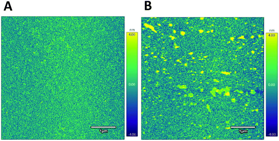 | ||
| Fig. 6 AFM height images of an unmodified gold surface (A) and gold surface modified with I40 (B) imaged in water showing surface features over 4.0 nm in height present on the I40 modified surface that are absent on the unmodified surface. | ||
I40 stimuli-response characterization
Having achieved a reproducible I40 surface modification (Fig. 5), the stimuli-response was then characterized by exposing surface-immobilized I40 to varying molarities of sodium chloride (NaCl) salt and recording the impedance response. Exposing an I40 modified electrode to a high salt environment is expected to result in I40 collapse, reducing the available electrode surface area and decreasing the available diffusion pathways which hinders the kinetics of the redox couple exchange and results in an increase in charge transfer resistance.As an example of a single electrode, an increase in charge transfer resistance was observed after exposing an I40 modified electrode to a high salt (3.0 M NaCl) environment (Fig. 7). At the no salt concentration (DI water), a lower charge transfer resistance was observed consistent with the extended state of the I40 (12.9 kΩ). In the absence of salt, the decrease in intramolecular interactions at the surface associated with the extended state of the polymer would be expected to allow for greater accessibility of the redox couple at the electrode surface. The charge transfer resistance increased to 29.3 kΩ (a 16.4 kΩ increase) after exposure to a high salt environment, indicating an increase in the insulating layer on the electrode surface. Multiple trials of single, unique electrodes exposed to a high salt environmental stimulus found an average charge transfer resistance increase of 17.3 ± 0.9 kΩ compared to the absence of salt. The data in Fig. 7 is consistent with the hypothesis that surface-immobilized I40 undergoes collapse in a high salt environment, leading to a reduction in available diffusion pathways and/or electrode surface area for redox couple exchange.
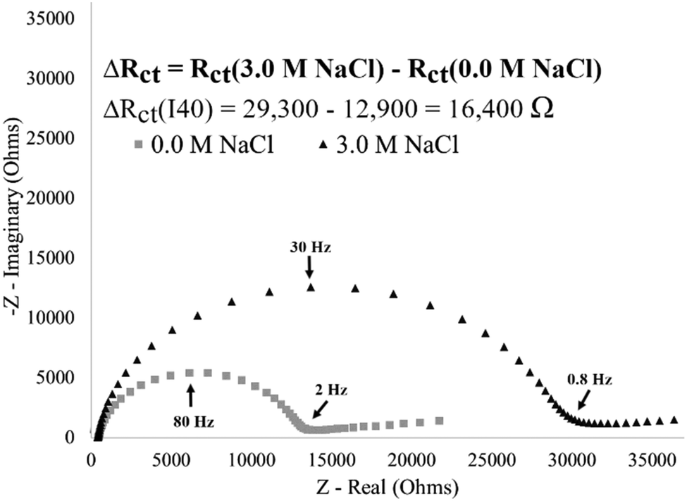 | ||
| Fig. 7 Impedance spectra for an I40 modified electrode showing the stimuli-response. A 16400 Ω increase in charge transfer resistance is observed from 0.0 M NaCl (12900 Ω) to 3.0 M NaCl (29300 Ω) environments. | ||
For an I40-Blocked modified electrode, an increase in charge transfer resistance of 84 Ω is observed after exposure to a high salt environment, indicating insignificant changes at the electrode surface (Fig. 8). As observed by EIS, Physiosorbed I40-Blocked electrode surfaces do not generate a strong stimulus response. This supports the hypothesis that the observed changes in charge transfer resistance from an I40 modified electrode can be attributed to the stimuli-responsive behaviour of I40 immobilized by a strong cysteine–gold attachment.
 | ||
| Fig. 8 Impedance spectra for an I40-Blocked modified electrode showing a lack of stimuli-response. An 84 Ω increase in charge transfer resistance from 0.0 M NaCl (495 Ω) to 3.0 M NaCl (579 Ω) environments. | ||
To measure the impedance response, the modified electrode was transferred from the experimental condition into a low molar salt, 10 mM [Fe(CN)6]3−/4− redox couple solution. The impedance response was recorded after exposing an I40 modified electrode to the 10 mM [Fe(CN)6]3−/4− overnight to ensure the molarity of the redox couple solution did not influence the stimuli-response. After exposure to the 10 mM [Fe(CN)6]3−/4− solution, the impedance response is similar to the 0.0 M NaCl condition. A 1.2 kΩ difference of charge transfer resistance was observed, indicating the molarity of the redox couple solution is sufficiently low not to significantly influence the surface morphological changes associated with a stimuli-response. Further details of this control experiment and Nyquist plot are included in ESI† (Fig. S5).
Reversibility of I40 stimuli-response
The reversibility of the stimuli-response was evaluated by comparing the impedance response from an I40 modified electrode after multiple exposures to no salt or high salt concentration environments (Fig. 9). Reversibility of the stimuli-response is demonstrated by the respective increase in charge transfer resistance (high salt and collapse state) or decrease in charge transfer resistance (no salt and extended state) from the same electrode. Additionally, the change in magnitude of charge transfer resistance is nearly identical for the transition from no salt to high salt concentrations (17250 Ω), as it is for the reverse (i.e., high salt to no salt concentrations) (18730 Ω) indicating the direction of the stimulus change does not influence the magnitude of response. Finally, the reversibility of the stimuli-response shows potential in reusable systems. Since the stimuli-response can be reversed, a single modified surface can be reused for multiple unique events, an important feature for development of low-cost technologies.39
 | ||
| Fig. 9 Impedance spectra of an I40 modified gold electrode after exposures to 0.0 M NaCl or 3.0 M NaCl showing agreement in charge transfer resistance and demonstrating stimuli-response reversibility. | ||
I40 stimuli-response with varying sodium chloride molarities
The stimuli-response of surface-immobilized I40 was further characterized by exposing an I40 modified electrode to varying molarities of sodium chloride (NaCl) (Fig. 10). The impedance response from an I40 modified electrode showed an increase in charge transfer resistance with increasing NaCl concentration. After exposure to the 0.0 M NaCl environment, the modified electrode had the lowest charge transfer resistance, consistent with the hypothesis of the extended state predominating at no salt concentrations. Exposing the modified electrode to increasing molarities of sodium chloride showed an initial increase in charge transfer resistance at 0.5 M NaCl with a saturation in the response after exposure to 0.75 M NaCl and 1.0 M NaCl. Agreement in the charge transfer resistance values for 0.75 M NaCl and 1.0 M NaCl concentrations indicate that the stimuli-response has been saturated, and the resulting structure is fully in the hypothesized collapsed state. Additionally, the impedance response from the 0.5 M NaCl condition falls between the maxima and minima for charge transfer resistance, providing evidence of intermediate states existing between the extended and collapsed state. Replicate data are included in the ESI† (Fig. S6).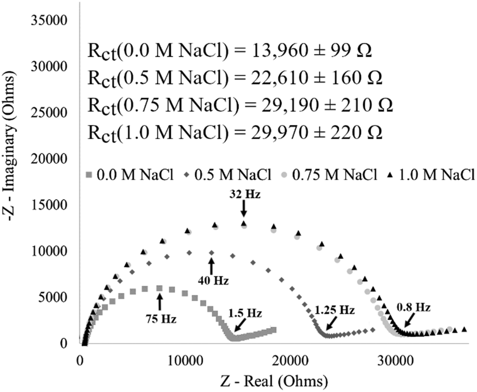 | ||
| Fig. 10 Impedance of an I40 modified electrode showing increasing saturation in the stimuli-response with an intermediate state between the maxima and minima. Replicate data are included in the ESI† (Fig. S6). | ||
This data supports the hypothesis that surface-immobilization of I40 constrains the polymer's ability to form intermolecular contacts to bury nonpolar regions of the polymer in response to increased sodium chloride molarity. This in turn necessitates the formation of intramolecular contacts of surface-immobilized ELP to achieve the same extent of hydrophobic burial as seen in ELP in solution. Our results are consistent with previous single molecule force spectroscopy measurements demonstrating that end-grafted ELPs undergo increasing degrees of collapse with increasing salt concentration.40 We hypothesize that this constraint increases the dynamic range and tunability of the ELP sensor response.
Conclusions
An elastin-like polymer (I40) was successfully immobilized on a gold surface, and stimuli-responsive behaviour, associated with the extension and collapse of surface-immobilized ELP, was monitored using electrochemistry. Quantifiable differences in charge transfer resistance were observed for I40-modified surfaces exposed to no salt versus high salt environments, suggestive of significant, dynamic changes in polymer morphology. Further electrochemical characterization of surface-immobilized I40 demonstrated a reproducible surface modification, as well as reversibility and tunability of the stimuli-responsive behaviour that can be generated by promoting the intramolecular response of ELP through surface-immobilization. We observed intermediate states between the maxima and minima which demonstrates potential for greater dynamic range of the surface beyond the typical extension and collapse characteristic. Future directions of this technology, integrated with EIS, could aid in greater kinetic and diffusion information about the ELP surface state and molecular diffusion through the ELP layer.Conflicts of interest
There are no conflicts to declare.Acknowledgements
The authors would like to acknowledge NSF EAGER CBET 1638896 (JMH), NSF EAGER CBET 1638893 (ERMB), and NSF MRI 1531296 for the funding of this work. The authors would also like to acknowledge Collaborative Research Excellence (CoRE) Pilot Research Project at the University of New Hampshire.References
- J. R. Simon, N. J. Carroll, M. Rubinstein, A. Chilkoti and G. P. López, Nat. Chem., 2017, 9, 509–515 CrossRef CAS.
- K. M. Ruff, S. Roberts, A. Chilkoti and R. V. Pappu, J. Mol. Biol., 2018, 430, 4619–4635 CrossRef CAS.
- R. Petitdemange, E. Garanger, L. Bataille, W. Dieryck, K. Bathany, B. Garbay, T. J. Deming and S. Lecommandoux, Biomacromolecules, 2017, 18, 544–550 CrossRef CAS.
- T. Kowalczyk, K. Hnatuszko-Konka, A. Gerszberg and A. K. Kononowicz, World J. Microbiol. Biotechnol., 2014, 30, 2141–2152 CrossRef CAS PubMed.
- D. W. Urry, J. Protein Chem., 1988, 7, 1–34 CrossRef CAS PubMed.
- C. H. Luan and D. W. Urry, J. Phys. Chem., 1991, 95, 7896–7900 CrossRef CAS.
- Y. Cho, Y. Zhang, T. Christensen, L. B. Sagle, A. Chilkoti and P. S. Cremer, J. Phys. Chem. B, 2008, 112, 13765–13771 CrossRef CAS.
- D. W. Urry, J. Phys. Chem. B, 1997, 101, 11007–11028 CrossRef CAS.
- K. Trabbic-Carlson, D. E. Meyer, L. Liu, R. Piervincenzi, N. Nath, T. LaBean and A. Chilkoti, Protein Eng., Des. Sel., 2004, 17, 57–66 CrossRef CAS PubMed.
- D. W. Urry, S. Peng and T. Parker, J. Am. Chem. Soc., 1993, 115, 7509–7510 CrossRef CAS.
- J. C. Rodríguez-Cabello, F. J. Arias, M. A. Rodrigo and A. Girotti, Adv. Drug Delivery Rev., 2016, 97, 85–100 CrossRef PubMed.
- J. R. McDaniel, D. J. Callahan and A. Chilkoti, Adv. Drug Delivery Rev., 2010, 62, 1456–1467 CrossRef CAS.
- G. L. Bidwell and D. Raucher, Adv. Drug Delivery Rev., 2010, 62, 1486–1496 CrossRef CAS.
- B. C. Dash, S. Mahor, O. Carroll, A. Mathew, W. Wang, K. A. Woodhouse and A. Pandit, J. Controlled Release, 2011, 152, 382–392 CrossRef CAS PubMed.
- E. R. M. Balog, K. Ghosh, Y.-I. Park, V. Hartung, P. Sista, R. C. Rocha, H.-L. Wang and J. S. Martinez, ACS Biomater. Sci. Eng., 2016, 2, 1135–1142 CrossRef CAS.
- D. L. Nettles, A. Chilkoti and L. A. Setton, Adv. Drug Delivery Rev., 2010, 62, 1479–1485 CrossRef CAS PubMed.
- J. C. Rodríguez-Cabello, I. González de Torre, A. Ibañez-Fonseca and M. Alonso, Adv. Drug Delivery Rev., 2018, 129, 118–133 CrossRef PubMed.
- S. Singh, D. E. Demco, K. Rahimi, R. Fechete, J. C. Rodriguez-Cabello and M. Möller, Soft Matter, 2016, 12, 6240–6252 RSC.
- A. Tarakanova, W. Huang, A. S. Weiss, D. L. Kaplan and M. J. Buehler, Biomaterials, 2017, 127, 49–60 CrossRef CAS PubMed.
- S. R. MacEwan and A. Chilkoti, Biopolymers, 2010, 94, 60–77 CrossRef CAS.
- S. Roberts, M. Dzuricky and A. Chilkoti, FEBS Lett., 2015, 589, 2477–2486 CrossRef CAS.
- A. Matt, B. Kuttich, I. Grillo, S. Weißheit, C. M. Thiele and B. Stühn, Soft Matter, 2019, 15, 4192–4199 RSC.
- K. Widder, S. R. MacEwan, E. Garanger, V. Núñez, S. Lecommandoux, A. Chilkoti and D. Hinderberger, Soft Matter, 2017, 13, 1816–1822 RSC.
- J. Hyun, W. K. Lee, N. Nath, A. Chilkoti and S. Zauscher, J. Am. Chem. Soc., 2004, 126, 7330–7335 CrossRef CAS PubMed.
- H.-C. Huang, P. Koria, S. M. Parker, L. Selby, Z. Megeed and K. Rege, Langmuir, 2008, 24, 14139–14144 CrossRef CAS.
- N. Nath and A. Chilkoti, Adv. Mater., 2002, 14, 1243–1247 CrossRef CAS.
- G. V. R. Rao, S. Balamurugan, D. E. Meyer, A. Chilkoti and G. P. López, Langmuir, 2002, 18, 1819–1824 CrossRef CAS.
- A. Valiaev, N. I. Abu-Lail, D. W. Lim, A. Chilkoti and S. Zauscher, Langmuir, 2007, 23, 339–344 CrossRef CAS PubMed.
- L. Marvin, W. Paiva, N. Gill, M. A. Morales, J. M. Halpern, J. Vesenka and E. R. M. Balog, PLoS One, 2019, 14, e0216406 CrossRef.
- W. Hassouneh, T. Christensen and A. Chilkoti, Current Protocols in Protein Science, John Wiley & Sons, Inc., Hoboken, NJ, USA, 2010, ch. 6, pp. 6.11.1–6.11.16 Search PubMed.
- Y. Xue, X. Li, H. Li and W. Zhang, Nat. Commun., 2014, 5, 4348 CrossRef CAS.
- H. Gronbeck, A. Curioni and W. Andreoni, J. Am. Chem. Soc., 2000, 122, 3839–3842 CrossRef.
- A. Tlili, A. Abdelghani, S. Hleli and M. Maaref, Sensors, 2004, 4, 105–114 CrossRef CAS.
- T. Yamaoka, T. Tamura, Y. Seto, T. Tada, S. Kunugi and D. A. Tirrell, Biomacromolecules, 2003, 4, 1680–1685 CrossRef CAS.
- P. Eyer, F. Worek, D. Kiderlen, G. Sinko, A. Stuglin, V. Simeon-Rudolf and E. Reiner, Anal. Biochem., 2003, 312, 224–227 CrossRef CAS.
- J. R. Winther and C. Thorpe, Biochim. Biophys. Acta, 2014, 1840, 838–846 CrossRef CAS PubMed.
- M. A. Morales and J. M. Halpern, Bioconjugate Chem., 2018, 29, 3231–3239 CrossRef CAS.
- H. M. Watkins, F. Ricci and K. W. Plaxco, Langmuir, 2018, 34, 14993–14999 CrossRef CAS.
- J. A. Goode, J. V. H. Rushworth and P. A. Millner, Langmuir, 2015, 31, 6267–6276 CrossRef CAS PubMed.
- A. Valiaev, D. W. Lim, S. Schmidler, R. L. Clark, A. Chilkoti and S. Zauscher, J. Am. Chem. Soc., 2008, 130, 10939–10946 CrossRef CAS PubMed.
Footnote |
| † Electronic supplementary information (ESI) available. See DOI: 10.1039/c9sm01681c |
| This journal is © The Royal Society of Chemistry 2019 |