
 Open Access Article
 This Open Access Article is licensed under a Creative Commons Attribution-Non Commercial 3.0 Unported Licence
Mechanical phase inversion of Pickering emulsions via metastable wetting of rough colloids†
Michele
Zanini‡
ab,
Alberto
Cingolani‡
c,
Chiao-Peng
Hsu
a,
Miguel Ángel
Fernández-Rodríguez
 a,
Giuseppe
Soligno
d,
Anna
Beltzung
c,
Stefano
Caimi
c,
Denise
Mitrano
e,
Giuseppe
Storti
c and
Lucio
Isa
*a
a,
Giuseppe
Soligno
d,
Anna
Beltzung
c,
Stefano
Caimi
c,
Denise
Mitrano
e,
Giuseppe
Storti
c and
Lucio
Isa
*a
aLaboratory for Soft Materials and Interfaces, Department of Materials, ETH Zürich, Zürich, Switzerland. E-mail: lucio.isa@mat.ethz.ch
bVan’t Hoff Laboratory for Physical and Colloid Chemistry, Debye Institute for Nanomaterials Science, Utrecht University, Utrecht, The Netherlands
cDepartment of Chemistry and Applied Biosciences, Institute for chemical and bioengineering, ETH Zürich, Zürich, Switzerland
dCondensed Matter and Interfaces, Debye Institute for Nanomaterials Science, Utrecht University, Utrecht, The Netherlands
eProcess Engineering Department, Eawag, Swiss Federal Institute of Aquatic Science and Technology, Switzerland
First published on 11th September 2019
Abstract
The possibility to invert emulsions from oil-in-water to water-in-oil (or vice versa) in a closed system, i.e. without any formulation change, remains an open fundamental challenge with many opportunities for industrial applications. Here, we propose a mechanism that exploits particle surface roughness to induce metastable wetting and obtain mechanically-responsive Pickering emulsions. We postulate that the phase inversion is driven by an in situ switch of the particle wettability from metastable positions at the interface following the input of controlled mechanical energy. Oil-in-water emulsions can be prepared at low energy using mildly hydrophobic rough colloids, which are dispersed in water and weakly pinned at the interface, and switched to water-in-oil emulsions by a second emulsification at higher energy, which triggers the relaxation of the particle contact angle. The same principle is demonstrated for the complementary emulsions using mildly hydrophilic colloids initially dispersed in oil. Our experiments and simulations support that the delicate interplay between particle surface design during synthesis and the energy of the emulsification process can encode a kinetic pathway for the phase inversion. Both organic and inorganic nanoparticles can be used, allowing for the future implementation of our strategy in a broad range of smart industrial formulations.
Introduction
Colloidal particles and liquid interfaces bear significant importance in addressing fundamental scientific questions and present many opportunities in industrial applications, ranging from food1 to heavy oil processing.2,3 Since the seminal observations of Ramsden and Pickering,4,5 partially wetting colloidal particles trapped at liquid interfaces have been proposed as excellent emulsion and foam stabilizers. Depending on their wettability, particles larger than a few nanometers can have energies binding them to a fluid interface that easily exceed thermal energy by several orders of magnitude.6,7 Such trapping can thus provide kinetic stabilization, effectively arresting coalescence and phase separation of emulsions8–10 and foams.11,12In particle-stabilized emulsions, analogously to surfactants, the particle contact angle θ plays a fundamental role in defining the emulsion type.13–15 In fact, hydrophobic (θ > 90°) particles have the tendency to stabilize water droplets in oil (w/o), while hydrophilic colloids (θ < 90°) preferentially form oil-in-water emulsions (o/w). Thus, canonically, two kinds of particles are required to stabilize the two types of emulsions. This scheme can be challenged by using more complex particles, i.e. with shape, chemical functionality and surface texture deviating from uniform, smooth and rigid spherical colloids.16,17 The huge development in the fabrication of patchy,18–20 non-spherical21,22 and unconventional particles, i.e. presenting tunable surface functionalization,23 morphology24–27 and architecture,28,29 provides ample opportunities for new stabilization strategies.
Surface roughness and its tailoring have in particular emerged as a powerful tool to control emulsion-stabilization processes.30–32 The key design concept is that, akin to macroscopic surfaces,33 surface roughness may induce large contact angle hysteresis at the single-particle level, i.e. a significant difference in the particle contact angle when adsorbing from the oil phase (advancing contact angle) or when adsorbing from water (receding contact angle). If the hysteresis is large enough, rough colloids can be made into “universal stabilizers”, namely particles that can stabilize both w/o and o/w emulsions depending exclusively on the phase from which they breach the interface.32,34 This concept only works if the contact line is strongly pinned and thermally-driven relaxations towards equilibrium are prevented.35–39 It has for instance been shown that a sufficient number of spherical-cap asperities in the >10 nm range can lead to pinning energies greatly exceeding kBT.32,40 Finally, the colloid size generally affects the size of the emulsified droplets.16
Emulsion inversion, that is the switching of emulsion type from o/w to w/o or vice versa, can be achieved via different approaches. It can for instance be obtained by varying the water-to-oil ratio41 (catastrophic inversion) or by tuning the particle contact angle42 (transitional phase inversion). The latter can be triggered by variations of temperature,43 surfactant concentration,14,44 pH and ionic strength,45–48via ex situ drying processes49,50 or by changing the kind of apolar phase.51 Analogous arguments also proved to be valid for foams.52
Nevertheless, all of these routes typically require a change in the formulation during emulsification and cannot take place in a closed system once the first kind of emulsion has been created. Rare exceptions report the switch from w/o to o/w emulsions by either varying the particle concentration in the apolar phase53 or the mixing time.54 In these studies, partially hydrophobized, aggregated fumed silica were used. At high particle concentrations or short emulsification times, w/o emulsions were observed; conversely, o/w emulsions were obtained for low solid loading and longer mixing. The authors suggested that the fumed silica particles in oil consisted of flocs, which used up silanol groups to build the interparticle bonds, resulting in clusters that were effectively more hydrophobic than single particles. In this case, emulsion inversion was possible via a collective mechanism involving multi-particle aggregates, which formed weaker structures at low solid loading and broke up over longer mixing time. The possibility to invert emulsions in a closed system by the design and control of single-particle properties remains an experimentally untapped possibility, previously only theoretically proposed.15
By tailoring particle surface roughness and adsorption kinetic pathways, we herein propose a general strategy to obtain stimulus-responsive Pickering emulsions able to undergo phase inversion upon the externally triggered mechanical relaxation of the stabilizers’ contact angle. The strategy is represented in Fig. 1. We start by synthesizing colloidal particles with controlled surface roughness and surface chemistry so that they have a mild preferential wetting for one of the two fluids, i.e. water or oil, but they may also be dispersed in the other one, i.e. oil or water, respectively. In particular, we disperse inorganic, (mildly) hydrophilic rough colloids in oil and organic, (mildly) hydrophobic rough colloids in water. Upon a first emulsification step, using low mechanical energy, w/o and o/w emulsions are found in the two cases, respectively. This result stems from contact-line pinning and trapping of the rough colloids in metastable positions at the interface. Here, the mechanical input of the emulsification process is not strong enough to allow the de-pinning and relaxation of the contact line over the particle surface, required to move them toward their thermodynamic equilibrium position. This step follows the existing design principle for “universal stabilizers”,32,40 but, uniquely, in this work the full relaxation of the contact line can be induced by a second emulsification step at higher energy. In this case, the energy input is large enough to transport the rough particles through the interface, allowing them to relax from their initial metastable positions toward equilibrium. Correspondingly, the equilibrium w/o emulsions are found for the organic, hydrophobic rough colloids initially dispersed in water and o/w emulsions are obtained for the inorganic, hydrophilic rough colloids initially suspended in oil, respectively. Given the corresponding change of wettability from “kinetically” hydrophilic to “thermodynamically” hydrophobic (and vice versa), we propose that this causes an inversion of the local curvature of the droplets, leading to a mechanical phase inversion of the emulsion.15 The whole process can be performed in a closed system, i.e. without altering the system's composition or adding any extra component. The inversion stems only from the control of the particle metastability at the interface, which is encoded a priori in the surface design during the synthesis; particles need to have surfaces heterogeneous enough to pin the contact line during gentle emulsification, but which additionally allow for relaxation upon stronger mechanical agitation. In this way, roughness becomes a dynamic tool to control emulsion stability.
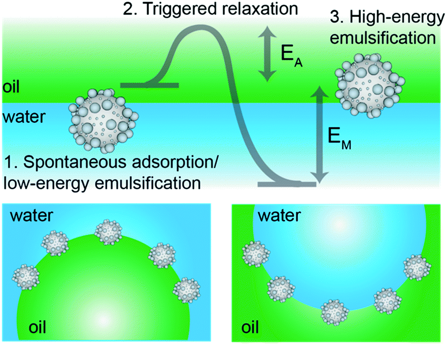 | ||
| Fig. 1 Mechanical phase inversion of Pickering emulsions. The scheme presents the process for the mechanical phase inversion of Pickering emulsions stabilized by the metastable wetting of rough colloids. In particular, we show the case of the inversion from o/w to w/o emulsions using mildly hydrophobic rough particles initially dispersed in water. The same line of thinking can be applied to the switching from w/o to o/w emulsions using mildly hydrophilic rough particles dispersed in oil before emulsification. | ||
To demonstrate the general validity of our idea, we present hereafter two complementary sets of experiments. First, we synthesized organic, rough and moderately hydrophobic particles, which we dispersed in water and emulsified with equal amounts of n-decane to obtain o/w emulsions at low shear and water droplets in oil at higher emulsification energies. In complementary experiments, we synthesized inorganic, rough and mildly hydrophilic colloids, which we dispersed in n-decane (oil phase) and emulsified with equal amounts of water to obtain w/o emulsions at low input energies and o/w droplets at higher shear. The experiments are finally correlated to numerical simulations showing the free-energy trajectory of adsorbing colloids, which clearly highlights the presence of roughness-dependent metastable minima, underpinning the proposed mechanism for the mechanical inversion of the emulsions (Fig. 1).
Results
Particle fabrication
Our organic particles (average size, D = 68 ± 4 and 120 ± 10 nm) present a core–shell architecture with a styrene-divinylbenzene (St-DVB) copolymer in the outer layer. The latter is directly and continuously grown on different seeds (cores) via semi-batch emulsion polymerization25,55,56 (Fig. 2A and B). According to the desired final surface morphology, we adopted two strategies, both involving a direct switch from the core mixture feed to the shell one. In the case of standard smooth particles, hereon termed PS-I, the core already consists of poly(styrene-co-divinylbenzene) and the addition of the St-DVB monomer only results in a particle size increase without altering the morphology nor the composition (Fig. 2A and Table S1 in the ESI†). In the case of rough particles (PS-II), the core instead consists of poly(acrylonitrile) and the addition of the second feed containing St-DVB causes a phase separation during growth, due to the poor compatibility of the two polymeric matrices in the blend (no compositional gradient, Fig. 2, synthesis path I). This phase separation in turns leads to the emergence of rough surfaces.25,56,57 The so-produced particles are hereon termed PS-II. For both PS-I and PS-II particles, the shell growth is carried out in so-called starved conditions, where the monomers are fed to the reaction vessel at a flow rate much lower than their consumption rate by reaction, thus ensuring the production of a copolymer with instantaneous composition equal to that of the fed monomer mixture.58 In this way, the control of the particle architecture (core/shell) and composition becomes straightforward28,29,59 Moreover, since St and DVB are the only monomers added during the shell growth, a chemically uniform polystyrene-based surface is ensured for both sets of particles. The same concept can also be used to produce particles with a smoother surface (see Fig. 2B, synthesis path II, Tables S2, S3 and Fig. S1 in the ESI†), when the feed is gradually changed (moderate compositional gradient) and a slower core-to-shell transition is imposed. In this case, even though tuning the compositional gradient between core and shell enables a finer control over the roughness, it inevitably implies a heterogenous chemical composition of the particle surface. For this reason, we later limit our emulsification studies to the PS-I and PS-II particles, which are compositionally analogous and thus allow isolating the effects of roughness. They have a moderately hydrophobic surface and are charge-stabilized in aqueous suspensions (ξ ∼ −30 mV) (see Fig. S2 and Sections S1 and S3 in the ESI†). Emulsification experiments on the other particle batches are presented in the ESI,† together with their surface morphology characterization (Fig. S5 and Section S2 in the ESI†).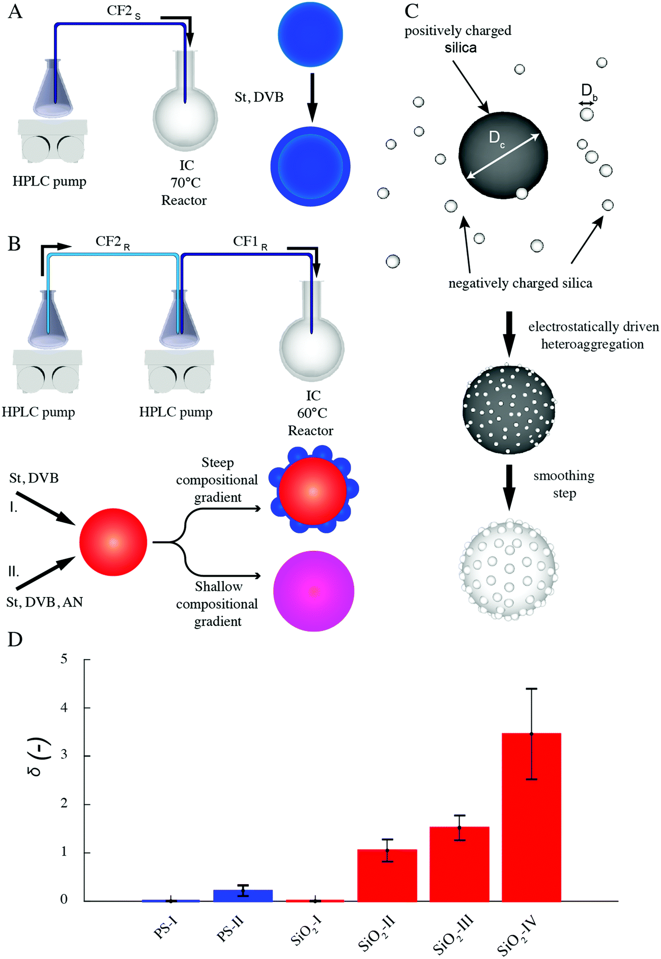 | ||
| Fig. 2 Synthesis of organic and inorganic rough colloids. (A) Synthesis scheme of organic homo-polymer core–shell smooth particles through two-step semibatch emulsion polymerization. (B) Synthesis scheme of organic composite rough particles through two-step semibatch emulsion polymerization and phase separation; different feeds (I, II) lead to various morphologies and surface compositions. (C) Preparation of all-silica raspberry-like rough colloids via electrostatically driven heteroaggregation followed by surface smoothing. (D) Surface roughness of the various rough colloids expressed in terms of the dimensionless parameter δ for the organic (blue) and inorganic (red) particles. The data are obtained from single-particle AFM analysis over at least 20 particles. Each bar represents the mean value and the error bars indicate the standard deviation extracted from the data distributions. | ||
The inorganic rough colloids are instead all-silica raspberry-like particles (Fig. 2C). They are fabricated by the electrostatically driven heteroaggregation of negatively charged silica nanoparticles (Db = 22 ± 2 or 39 ± 4 nm) onto larger silica colloids (Dc = 161 ± 15, 374 ± 14 nm and 588 ± 21 nm), whose surface is rendered positively charged via polyelectrolyte adsorption. This initial step is followed by the controlled heteronucleation of silica layers (smoothing layer) on the raspberry-like particle surface via a sol–gel route.24,32 The surface roughness can be finely controlled by selecting the core-to-nanoparticles size ratio and by adjusting the thickness of the smoothing layer (∼10 nm). Notably, the asperity lateral dimensions and height can be independently tailored through these two parameters. The as-produced hydrophilic raspberry-like particles are then partially hydrophobized using a uniform coating of bromo-silane to obtain a close-to-neutrally wetting surface, which makes them dispersible in both polar and apolar fluids.32,60 See the Methods section and ESI,† Table S4 and Fig. S3 for more details on the synthesis procedure.
As reported in Fig. 3A and B, the particles’ surface topography is imaged and characterized by both scanning electron microscopy (SEM) and atomic force microscopy (AFM). Hereon, we describe the surface roughness with the dimensionless parameter 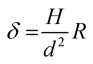 , where H is the average asperity height, d the mean asperity-to-asperity distance and R the particle radius. In this way, provided that the asperities have comparable shapes, it is possible to differentiate the wetting behavior of colloids having different sizes of the core but decorated with features presenting the same roughness amplitude. The δ parameter directly describes the combined effect of number and size of asperities met by the moving three-phase contact line as the particle crosses the fluid interface. H/d in fact represents an average roughness scale, while R/d is directly proportional to the linear density of asperities along the contact line. These two quantities are necessary to estimate a characteristic single-particle pinning force/energy,61 which we also use in our calculations (Table S5 and Section S4 in the ESI†). In the ESI† (Section S2 and Fig. S4), we provide a direct comparison of the aforementioned roughness characterization with standard procedures and operators. The proposed fabrication methods allow synthesizing both organic and inorganic particles with roughness ∼0 < δ < 4, irrespective from their composition.
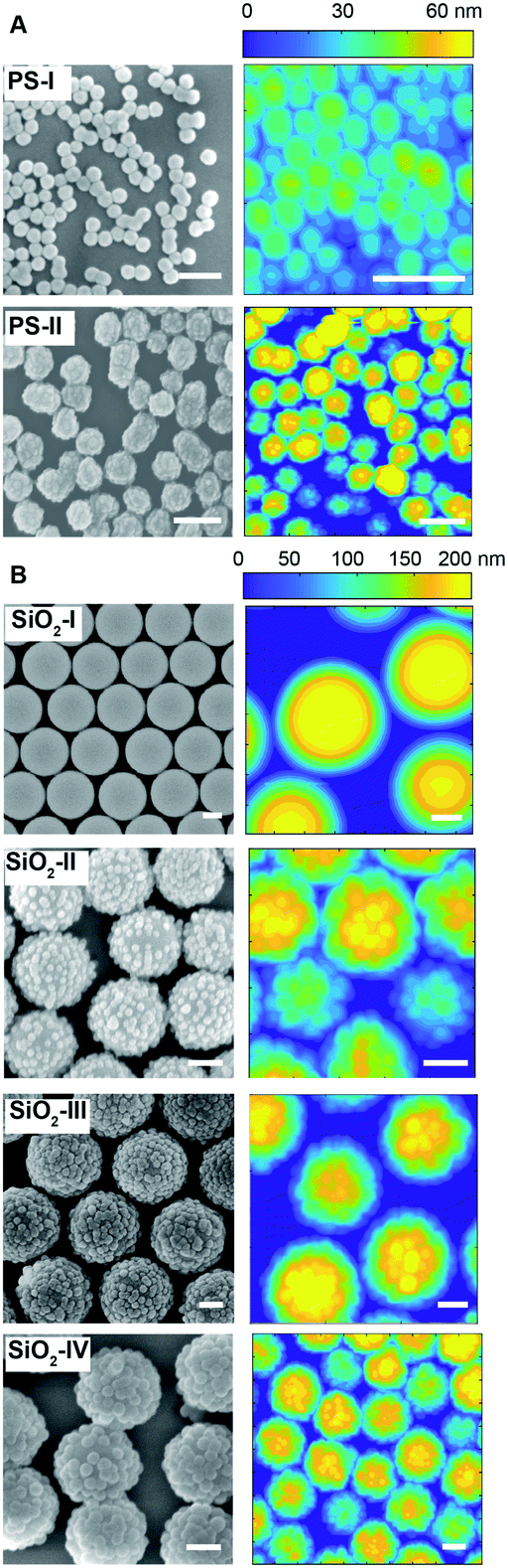 | ||
| Fig. 3 Topographical particle surface characterization. SEM and AFM surface analysis of the organic (A) and inorganic (B) rough colloids. Scale bars: 200 nm. | ||
Single-particle contact angle upon spontaneous adsorption
After the synthesis and characterization, we measure the particle wettability as a function of surface roughness by means of a freeze-fracture shadow-casting technique coupled with cryo-SEM (FreSCa cryo-SEM).62,63 Hereafter, particles adsorbing from the polar and apolar phase will be labeled with “w” and “o”, respectively. Particles spontaneously adsorbing at a flat water/n-decane interface from either the aqueous or the oil phase are immobilized by shock-freezing. After removal of the frozen oil, tungsten is deposited on the vitrified aqueous phase with a well-defined tilt angle (30°) in high-vacuum and cryo conditions. Analogously to a sundial, particles protruding through the interface can cast a shadow. By measuring the shadow length and knowing the particle geometry, we extract their contact angle with single-particle resolution (see Fig. 4). Smooth bromo-modified silica colloids adsorbing from n-decane (SiO2-IO) show a contact angle of ∼70°, which coincides with their equilibrium position at the interface as previously demonstrated.32 Rougher particles modified in the same fashion, which also spontaneously adsorb from the apolar phase (SiO2-IIO, SiO2-IIIO and SiO2-IVO), display increasing contact angle values, becoming effectively hydrophobic in spite of their mildly hydrophilic surface chemistry. This trend confirms previous observations for larger colloids decorated with larger asperities and bearing the same surface functionality.32 A mirrored behavior is observed for the organic rough particles adsorbing from water. The smooth PS reference (PS-Iw) reaches its equilibrium value of θ ≈ 105° (see Fig. 4), but the rougher colloids bearing the same surface chemistry (PS-IIw) become effectively hydrophilic due to trapping in metastable positions. The relation between the width of the contact angle distribution and the spread between the expected and the mean measured contact angle for rough colloids is reported in the Fig. S11 in the ESI.† The measured contact angle does not spontaneously evolve over times up to 10![[thin space (1/6-em)]](https://www.rsc.org/images/entities/char_2009.gif) 000 s (see ESI,† Fig. S6), suggesting that contact line relaxation for our rough colloids cannot proceed via thermally activated hopping events.35
000 s (see ESI,† Fig. S6), suggesting that contact line relaxation for our rough colloids cannot proceed via thermally activated hopping events.35
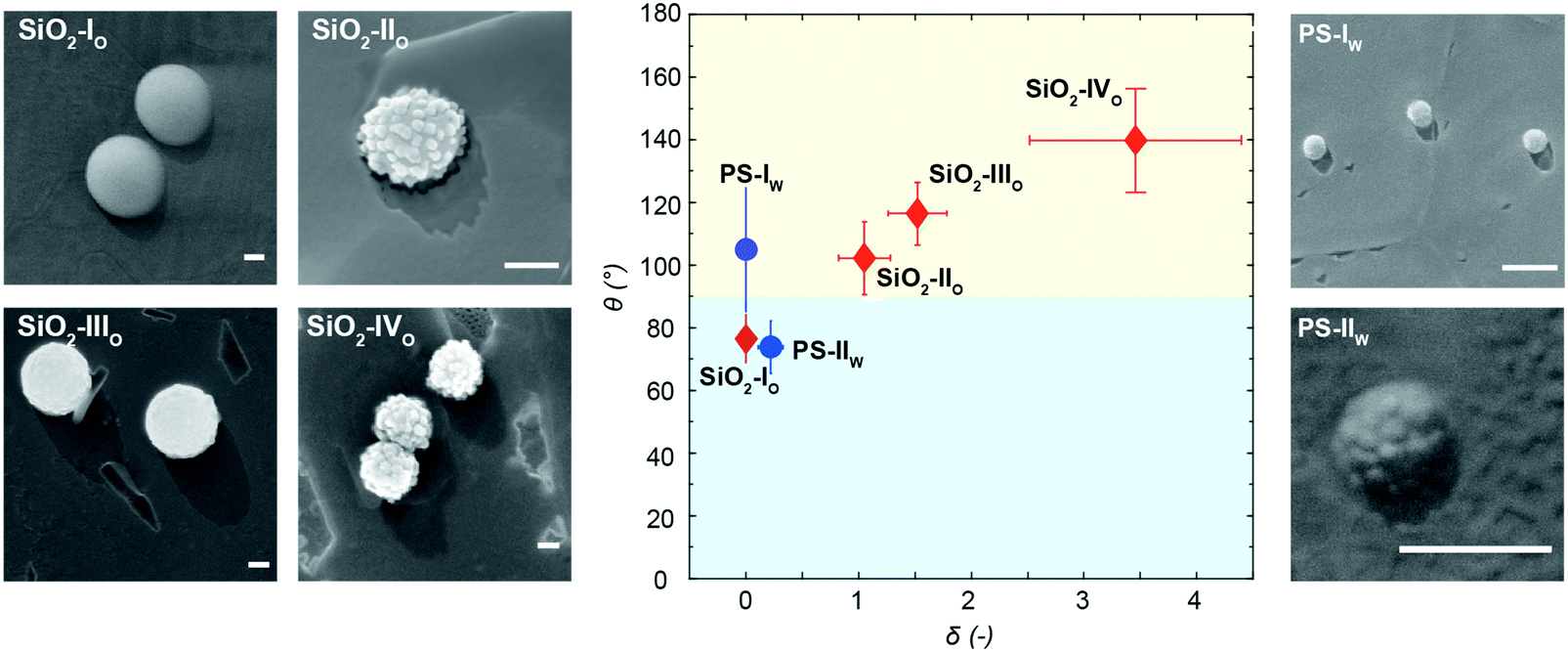 | ||
| Fig. 4 Particle contact angle upon spontaneous adsorption. Measured contact angles as a function of particle surface roughness from FreSCa cryo-SEM images at a water/n-decane interface. The red diamonds refer to the bromo-modified silica colloids spontaneously adsorbing from the oil phase. The blue dots refer to the organic beads spontaneously adsorbing from the aqueous phase. Each point represents the mean value and the error bars indicate the standard deviation extracted from the data distributions. The subscripts following the particle name indicate the phase, in which the particles are initially dispersed. Particles are immobilized shortly after adsorption (<1 minute). Scale bars: 200 nm. | ||
Mechanical phase inversion of Pickering emulsions
In analogy to the Bancroft rule,9,15,64 as we will discuss later, (effectively) hydrophobic particles, such as PS-IO, SiO2-IIO, SiO2-IIIO and SiO2-IVO should give rise to w/o emulsions, while (effectively) hydrophilic particles, such as SiO2-IO and PS-IIW, to o/w emulsions. We show here that, for rough colloids trapped in metastable positions, this may or may not be true depending on the energy input during emulsification. We start by emulsifying 1:1 water-to-oil mixtures in the presence of our colloids initially dispersed in either water or oil. We choose 1:1 mixtures to avoid any compositional bias to determine the emulsion type. As reported in Fig. 5A–C, PS-IW can only stabilize water-in-oil emulsions irrespective of the emulsification method. The emulsion type is confirmed by the macroscopic appearance of the emulsion and by conductivity measurements, for which values close to zero are found and thus not reported. Conversely, PS-IIW produces o/w emulsions when mixed at low energies (4000 rpm – Fig. 5D or at 12000 rpm for <1 minute – Fig. 5E) and the opposite emulsion when mixed at high shear rates (≥12000 rpm) for periods longer than 1 minute or if directly ultra-sonicated (Fig. 5F). Interestingly, a short (≤1 min) and intense emulsification step at high shear rates (≥12000 rpm) generates a dispersed phase but it is not yet sufficient to induce phase inversion (Fig. 5E). In this case, conductimetry measurements are not feasible, due to the scarce thickness of the emulsion layer, but they are expected to match the conductivity of the continuous aqueous phase. Both fluorescence imaging in a drop test and conductivity experiments confirm the phase switch. In the drop test, emulsions were diluted in an excess of the respective continuous phase, previously labelled with a fluorescent dye. In particular, we labeled water with a hydrophilic dye (Alexa Fluor 488 dye or Rhodamine B isothiocyanate) and n-decane with a hydrophobic one (Nile red or BODIPY 493/503). Therefore, in the drop test, o/w emulsions show dark oil droplets in a fluorescently labeled water background (Fig. 5H), while w/o emulsions display dark water droplets dispersed in fluorescent oil (Fig. 5I). The non-sphericity observed for some droplets suggests the presence of a viscoelastic interface.12,65 While the results obtained for PS-IW confirm Bancroft-type predictions based on the wetting data from the FreSCa analysis, emulsions stabilized with PS-IIW follow the route proposed at the beginning of this manuscript. Notably, the mechanical switch can be triggered in situ, i.e. the same o/w emulsion produced at low shear rates can be inverted by a subsequent high-shear mixing or by ultra-sonication. As expected, mixtures with higher solid contents can stabilize larger volumes of the dispersed phase (see Fig. S7 in ESI†).
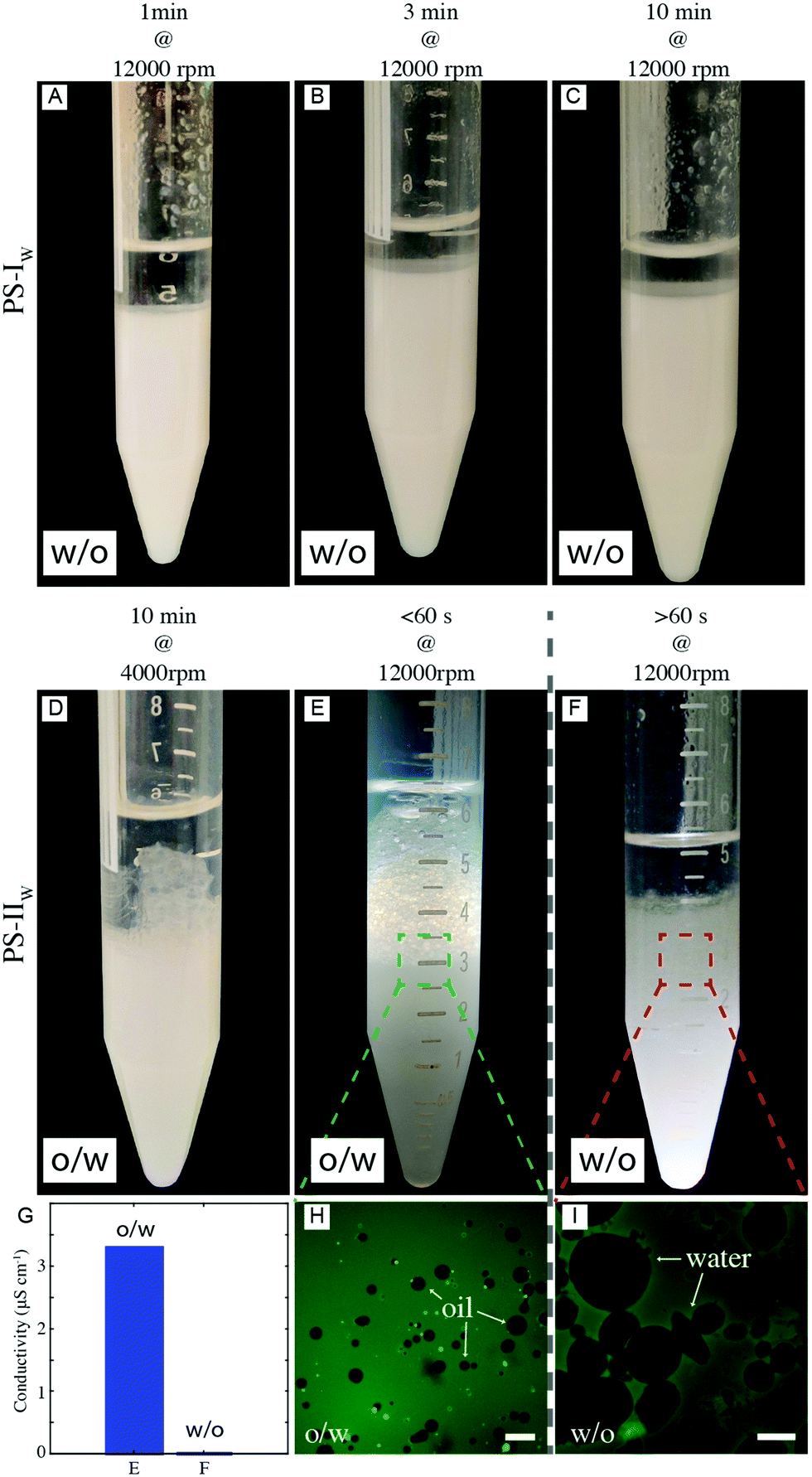 | ||
| Fig. 5 PS-stabilized Pickering emulsions. (A–C) Reference smooth and slightly hydrophobic PS-IW forms w/o emulsions irrespective of the emulsification time. 3.5 mL aqueous solution at 0.5 wt%, 3.5 mL n-decane. (D–F) Mildly hydrophobic and rough PS-IIW (3.5 mL at 0.5 wt%) emulsified with n-decane (3.5 mL) at different shear rates. (G) Measured emulsion conductivity for emulsions (E) and (F). (H) and (I) are fluorescence optical micrographs of (E) and (F), respectively. In (H), the emulsion (E) is diluted in fluorescently labelled milliQ water (Alexa Fluo 488); in (I), the emulsion (F) is diluted in fluorescently labelled n-decane (Bodipy 493/503). Scale bars are: (H) 20 μm, (I) 100 μm. | ||
In order to verify if the inversion scheme can also be followed by particles initially dispersed in the oil phase and to examine in more detail the role of varying roughness, we performed the complementary set of emulsification studies on four batches of bromo-silane functionalized all-silica raspberry-like particles, from the smooth reference SiO2-I to the roughest one SiO2-IV. In particular, only for intermediate roughness, i.e. for SiO2-III particles, it is possible to trigger the mechanical phase inversion of 1:1 water/n-decane emulsions, as shown in Fig. 6. In panels A–E, the SiO2-III colloids are initially dispersed in the aqueous phase (see Materials and Methods for details). Conversely, in Fig. 6F–J the same particles are suspended in n-decane. In both cases, the colloids are only transiently stable and sediment upon flocculation overnight. The emulsification studies are done over time scales for which no appreciable aggregation is seen at those particle concentrations.
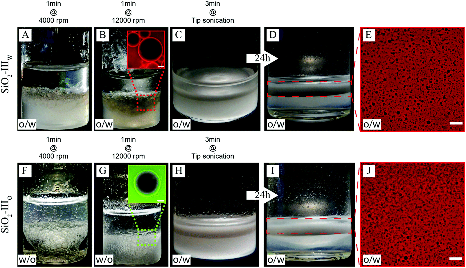 | ||
| Fig. 6 Silica-stabilized Pickering emulsions. Slightly hydrophilic and rough SiO2-III initially dispersed in both water (SiO2-IIIW A–D) and n-decane (SiO2-IIIO F–I) emulsified at different times and shear rates. Emulsions A and F are sheared for 1 min at 4000 rpm. Emulsions B and G are obtained upon shearing emulsions A and F for 1 min at 12000 rpm. In the inset of B, oil droplets are dispersed in excess water containing rhodamine B. In the inset of G, water droplets are dispersed in excess n-decane fluorescently labelled with BODIPY 493/503. Scale bar in B: 200 μm; in G: 100 μm. Emulsions C and H are obtained by tip sonicating the emulsions B and G for 3 min. In D and I, the tip-sonicated emulsions were left to rest for 24 h. E and J show fluorescence images of the emulsions displayed in panels D and I, respectively, after dilution in excess water labeled with rhodamine B. Scale bar 400 μm. | ||
Upon low-shear emulsification (1 min at 4000 rpm) the rough colloids follow a Bancroft-type behavior and stabilize the phase opposite to which they are initially suspended, i.e. oil droplets if initially dispersed in water (SiO2-IIIW – Fig. 6A) and water droplets in oil otherwise (SiO2-IIIO – Fig. 6F). By increasing the emulsification shear rates on the same emulsions (Fig. 6B and G, 1 min at 12000 rpm), a larger amount of dispersed phase can be emulsified but the type of emulsion does not change. The emulsion type is determined by fluorescence imaging in a drop test. The dispersed phase of the emulsion in Fig. 6B results dark when dispersed in excess water containing rhodamine B, indicating that the droplets consist of oil. Vice versa, the dispersed phase of the emulsion in Fig. 6G results dark when dispersed in excess n-decane fluorescently labelled by BODIPY 493/503, indicating the aqueous nature of the droplets. For these particular cases, conductivity measurements were not practicable due to the reduced volumes of the produced emulsions and the large droplet size. When the emulsions are further emulsified at even higher energy upon tip-sonication (Fig. 6C and H, 3 min tip sonication), we observe a marked change of the emulsions’ appearance. This is not only due to a drastic reduction of the droplet size (see Fig. 6E and J, ESI,† Fig. S10), but, for emulsion G, even more remarkably, the intense emulsification process eventually inverts the nature of the emulsion itself. This first qualitative confirmation of the inversion is given by the fact that in both cases (Fig. 6D and I) creaming is observed overtime. Moreover, the creamed turbid phase was diluted in excess water containing rhodamine B isothiocyanate to perform the drop test. The fact that the water phase appears bright in fluorescence imaging while the droplets are dark, as shown in Fig. 6E and J, indicates that in both cases o/w emulsions are found. This is further corroborated by conductimetry. Emulsions reported in Fig. 6D and I have a conductivity of ∼74 μS cm−1 and ∼39 μS cm−1. For reference, milliQ water containing 0.5 wt% of bromo modified SiO2-III has a conductivity of ∼79 μS cm−1 and the oil phase presents a practically null conductivity, hence the data confirm an aqueous continuous phase. These data confirm the previous observations obtained in the complementary experiments with the PS particles and add the fact that if the particles are already initially dispersed in their preferred fluid no inversion is possible and the Bancroft-type emulsion is directly stabilized. The evolution of the droplets size overtime is reported in the Fig. S10 in the ESI.†
In order to verify which window of experimental parameters allows the phase inversion, we carried out similar experiments with particles of lower and higher roughness compared to SiO2-III. Importantly, the smooth reference particles after bromo-silanization always stabilize o/w emulsions, irrespective of the phase they are initially dispersed in.32 Similarly, SiO2-II are not rough enough to effectively pin the contact line and stabilize the metastable w/o emulsions predicted by looking at the contact angle after spontaneous adsorption reported in Fig. 4. When initially dispersed in n-decane, they form o/w emulsions already at low mixing energies (Fig. 7A). Conversely, for the same conditions, rougher SiO2-IV particles form water droplets upon both low- (Fig. 7B) and high-energy emulsification (Fig. 7C), when initially suspended in n-decane. In this case, we deduce that the contact line is too strongly pinned to relax via mechanical inputs, even using a tip sonicator. To decrease the activation energy for contact-line relaxation, we lower the interfacial tension using the well-known water–cineole interface (γ = 16.9 mN m−1).51 In this way, the pinning energy is reduced by a factor ∼ 3, and SiO2-IV particles suspended in cineole allow the switching of w/o emulsions formed at low shear rates (Fig. 7D) to o/w emulsions emulsified at high shear rates (E). Therefore, the key to obtain the mechanical phase inversion of Pickering emulsions via metastable wetting relies on controlling the interplay between particle size, wettability and surface roughness, which, together with the value of the interfacial tension, determine a characteristic energy for contact angle pinning relative to the external energy input.
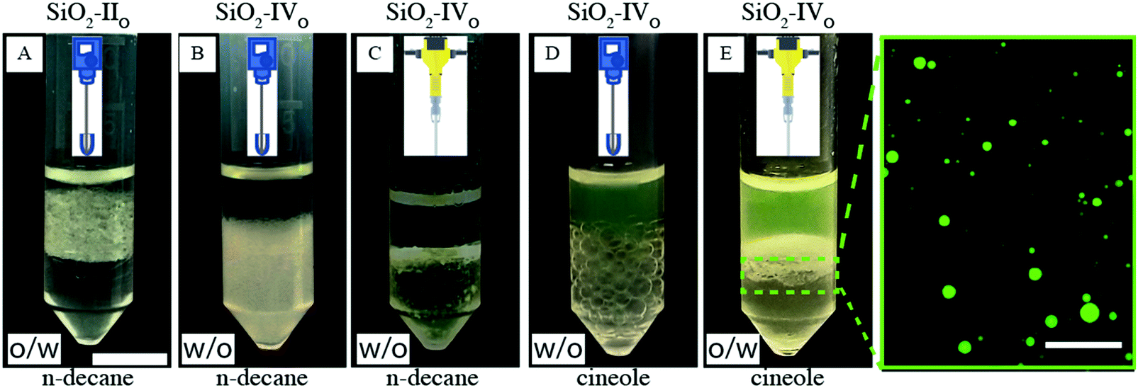 | ||
| Fig. 7 Surface roughness and phase inversion. (A) SiO2-II (1 wt%) suspended in n-decane emulsified at low input energies already form o/w emulsions. SiO2-IV (1 wt%) suspended in n-decane emulsified at low (B) and high input energies (C) always form w/o emulsions. SiO2-IV particles initially dispersed in cineole form w/o emulsions at low shear rates (D); the exact same emulsions can be inverted to o/w via tip sonication (E). In the zoomed-in micrograph, the fluorescently labelled cineole forms the dispersed phase. Scale bars: 1 cm and 100 μm for the macroscopic pictures and for the fluorescence micrograph, respectively. | ||
In order to provide further support to our arguments, in the next section we report numerical calculations of the free-energy trajectories of adsorbing rough colloids and compare the calculated metastable minima to simple experimental estimates.
Simulated adsorption kinetics
In a first set of simulations, we numerically calculate the equilibrium shape of the fluid–fluid interface including the capillary deformations induced by a rough colloidal particle. The interface is represented by a grid of points (see Fig. 8A–C), whereby a simulated-annealing (SA) algorithm is used to calculate the positions of the knots that minimize the thermodynamic potential of the system, hereinafter called energy E.66,67 The equilibrium particle height at the fluid–fluid interface is automatically found by this method, while the particle orientation is assumed fixed, for simplicity. The interface snapshots reported in Fig. 8A–C clearly show a corrugated contact line, with surface asperities inducing local deformations, confirming previous observations on larger and rougher silica colloids.32 In addition, we also employ an adaptation of this numerical method67 to simulate the quasi-static interfacial adsorption of a colloid with initial position in the fluid with lowest affinity, i.e. mimicking the adsorption of silica colloids from n-decane. This quasi-static simulation consists of a sequence of SA simulations in which the equilibrium shape of the fluid–fluid interface is computed with the constraint that the position of each knot cannot explore at a distance greater than Δ from its initial position in each individual SA simulation. Each SA simulation uses the final shape computed by the previous SA simulation as the input initial interface shape and the energy associated to the final shape of the interface of every SA simulation is calculated. In this way, we effectively sample the free-energy trajectory of a particle as a function of its position relative to the interface during adsorption. Through the various SA simulations, the shape of the interface evolves towards steady-state approximately following the steepest energy gradient path (the smaller the Δ, the better the approximation). More details are reported in the Sections S5 and S6 and Fig. S12 (ESI†).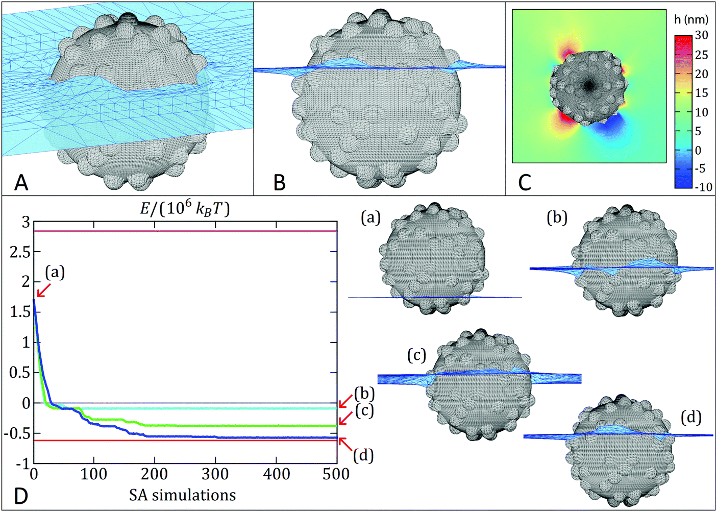 | ||
| Fig. 8 Simulated adsorption kinetics. (A) and (B) are, respectively, the 3D tilted and cross-sectional view of the equilibrium shape of the fluid–fluid interface (numerically computed) close to the particle, corresponding to the red line in the graph below. The black grid represents the colloid surface, while the blue grid is the fluid–fluid interface. The equilibrium contact angle (measured in the fluid below the interface) is 70° and the fluid-fluid surface tension is 0.053 N m−1. (C) Contour plot of the equilibrium height profile h of the fluid–fluid interface, where h = 0 corresponds to the level of the interface far away from the particle. (D) Evolution of the thermodynamic potential E (blue, cyan, green lines) during the quasi-static adsorption of a rough colloid at the interface (using different temperatures T0 in the SA simulations; cyan: 104 °C, green: 106 °C, blue: 107 °C). Magenta and black lines represent the desorption energy from the liquid with lower and higher affinity, respectively. The red line represents the equilibrium energy as dictated from the surface chemistry. The initial position of the colloid (see a profile view in (a)) is far from the equilibrium configuration shown in (B). The final configuration reached by the rough colloid is either a metastable state or the equilibrium (see profile views in (b–d)). | ||
Fig. 8D reports the quasi-static simulated adsorption kinetics using Δ = 0.05 for a rough colloid of radius R = 200 nm and decorated with 75 spherical asperities of radius 25 nm (δ ∼ 0.76, RMS ∼ 9.7 nm) at a fluid–fluid interface with surface tension of 0.053 N m−1. The smooth analogue would have an equilibrium contact angle of 70°. Remarkably, the proposed quasi-static approach reveals an exciting scenario for the contact line evolution, which confirms previous measurements indicating both a complex relaxation pathway, where a fast initial dynamics is followed by a slower relaxation35,36 and the presence of step-wise wetting relaxation events for rough surfaces.40 We perform three quasi-static simulations of 500 SA steps each, using three different initial temperatures T0 (T0 ≅ 104 °C, 106 °C and 107 °C respectively, with the temperature then decreases linearly to zero throughout ∼107 Monte Carlo steps in each SA simulation). In this way, T0 mimics the energy input level in an adsorption and emulsification process, while the particle surface wettability θ and roughness δ set the height of an energetic barrier for contact line evolution. The trade-off between them determines the adsorption kinetics. Interestingly, the energy E (see Section S5, eqn (2), ESI†) reported in Fig. 8D for the quasi-static simulation with lowest T0 (cyan line) monotonically decreases until it reaches (after about 50 SA simulations) a metastable configuration, at an energy approximately 0.5 × 10⁶kBT (T = room temperature) higher than the equilibrium configuration (red line), and then the particle remains stuck in this metastable configuration for the remaining SA simulations steps. Upon increasing input energy, i.e. T0 (green line), the particle manages to reach a lower-energy metastable configuration after about 200 SA simulations (0.15 × 10⁶kBT higher than the equilibrium configuration) and then it remains trapped in such metastable configuration for the remaining SA simulations. We clearly see here that the pathway to this final state consists of a sequence of discrete events, where the particle stays trapped in local minima for a number of SA steps, before the interface rearranges and moves to the next minimum until the final one is reached. Only in the quasi-static simulation with highest T0 (blue line) the particle basically reaches the equilibrium position (in about 300 SA steps). The snapshots in Fig. 8D represent the particle location relative to the interface in the final minimum and they correspond to effective contact angles of (b) 99°, (c) 84° and (d) 73° (very close to the value of 70° for the smooth surface), respectively, starting from an initial position of (a) 143°. The quasi-static simulations therefore confirm that the relaxation of the contact angle towards its equilibrium value can be triggered to different extents by varying external energy inputs. Small energy inputs can only cause partial relaxations, which are insufficient to invert the particle effective wettability, while higher energies are required for the task. The numerical results thus qualitatively confirm the behavior seen in the experiments. See Videos S3–S8 (ESI†) for an animation (3D tilted and profile views for the three quasi-static simulations) of the interface shape evolution during the particle quasi-static interfacial adsorption.
Remarkably, the pinning of the three-phase contact line is not imposed in the numerical model. Hence, the barriers that block the quasi-static interfacial adsorption of the colloid are not simulation artefacts, as confirmed by the fact that only the quasi-static simulation with highest temperature in the SA simulations reaches the energy minimum. Note that the quasi-static simulation is able to (possibly) overcome energetic barriers since a finite step size Δ is used (in the limit of an exact steepest energy gradient descent, any energetic barrier would block the quasi-static evolution of the system). By looking at the energy fluctuations with respect to the SA temperature (see Fig. S12 in the ESI†), we can estimate that these energy barriers range between ∼104kBT and ∼0.5 × 10⁶kBT. The values are close to the experimental estimations presented in more detail in the ESI,† Table S5. In particular, we find that mechanical inversion is possible if the energy barrier to move the contact line over the particle equator, and hence cause the effective wettability switch, is below ∼1.6 × 10⁵kBT. The energy barrier calculated for SiO2-IVO particles at the water/n-decane interface is ∼4.3 × 10⁵kBT, but drops down to ∼1.4 × 10⁵kBT at the water/cineole interface, supporting the evidence that mechanical inversion is possible in our experiments with the latter fluid combination, but not with the former one.
Discussion
In this work, we show that by engineering the interplay between particle surface properties, i.e. their wettability and surface roughness, and external energy inputs during emulsification, it is possible to design kinetic pathways that enable the in situ phase inversion of both o/w and w/o emulsions in closed systems using simple mechanical stimuli.In this respect, an appropriate surface design in terms of particle size, asperity height, shape and number sets the scales of the energy barriers experienced by single particles upon interfacial adsorption. These kinetic hurdles can be overcome by appropriate energy inputs during emulsification. The height of the barriers relative to the input energy therefore determines whether (and how far) the contact angle can relax toward equilibrium. Surface asperities can arrest the motion of particles through the interface, so that particle that have chemically hydrophilic (hydrophobic) surfaces adsorbing from the opposite fluid can be effectively hydrophobic (hydrophilic) and hence “unconventionally” stabilize w/o (o/w) emulsions. Upon energy injection and subsequent contact line motion, the same particles can cross the interface, approaching the contact angles defined by their surface chemistry and hence stabilize the “conventional” o/w (w/o) emulsions. The combination of cryo-SEM imaging and the macroscopic inversion of the emulsion type provides a compelling evidence of a change in the effective particle contact angle. The relation between particle wettability and type of stabilized emulsion is often referred to as the Bancroft rule, in analogy to the case of surfactant molecules. Even though the analogy is clear, there are important differences concerning the stabilization mechanisms. For surfactants, the Bancroft rule states that the continuous phase is the one in which the surfactants are soluble, and it has been shown that the stability in these conditions is due to the increased draining time of films of the continuous phase in the presence of excess solubilized surfactants when two droplets approach.68 As pointed out in the literature,6,15,69 the stability of Pickering emulsions is not due to the presence of excess particles in the continuous phase, but rather to the effects of kinetic trapping of single particles at the interface and the creation of steric layers on the droplets’ surfaces. In this respect, one associates particle wettability, and hence the emulsion type according to the Bancroft definition, to the possibility of dispersing the particles in what will become the continuous phase of the emulsion. The strategy that we propose here implies instead that, if particles are rough enough, and sufficiently close to neutral wettability, they can be dispersed in the unfavorable liquid, which will become the continuous phase of a long-lived metastable “anti-Bancroft” emulsion and which can be switched in situ to the stable “Bancroft” emulsion upon injection of sufficient mechanical energy. Cryo images of the Bancroft and long-lived anti-Bancroft emulsions are reported in Fig. S8 and S9 (ESI†), respectively.
Conclusions
The appeal of our considerations lies in the fact that they are derived from simple, single-particle properties. Even though emulsification processes are complex phenomena, where collective effects at the level of multiple particles and multiple droplets play an important role, specific particle features, such as their surface topography, can have strong consequences on formulation. In this respect, our experiments set the basis for further studies involving additional important aspects, such as the time evolution of droplet kind and size, the long-term stability of the various emulsions, or the role played by the ratio of the two fluid phases and the concentration of particles with tailored rough surfaces.Concluding, we envision that the findings of this work can help identify untapped routes for smart formulations in cosmetics, food and pharmaceutical applications but can also trigger new solutions for selective water- and oil-based purification and recovery processes.
Experimental (materials & methods)
n-Decane (99%, ABCR GmbH) and 1,8-cineole (>98%, TCI) are the oils used for emulsification. Ethanol (absolute, Merck), tetraethyl orthosilicate (TEOS, Sigma-Aldrich), ammonia solution (NH4OH, 25%, Merck), polydiallyldimethylammonium chloride (poly-DADMAC, 400–500 kDa, 20 wt%, Sigma-Aldrich), silica nanoparticles 39 nm (Klebosol, Clariant, Switzerland), silica nanoparticle 22 nm (Ludox TM; DuPont), hydrogen peroxide (H2O2, VWR, 30%), 3-aminopropyl-triethoxysilane (APTES, 97%, ABCR), α-bromoisobutyryl bromide (BrIn, 98%, Aldrich), triethylamine (99%, Sigma-Aldrich) and dichloromethane (anhydrous, 99.8%, Acros Organics), dichloromethane (99.99%, Acros Organics) were used to fabricate and covalently modify the inorganic rough particles. BODIPY 493/503 (Aldrich-Fine Chemicals) and Nile Red (ABCR-Chemicals) were used to trace the apolar phases; rhodamine B isothiocyanate (Sigma Aldrich) and Alexa Fluor 488 dye (ThermoFisher) were used to label the aqueous phase. Acrylonitrile (abbreviated AN, Aldrich chemistry ≥99.0%), styrene (abbreviated St Sigma Aldrich ≥99.0%) and divinylbenzene (abbreviated DVB, Sigma Aldrich) were the monomer used for emulsion polymerization. Water-soluble potassium persulfate (KPS) from Merck (ACS, Reag. Ph. Eur.) was employed as initiator. Potassium poly(ethylene glycol) 4-nonylphenyl 3-sulfopropylether (KPE) and sodium dodecyl sulfate (SDS, Sigma Aldrich ≥99%) were used as stabilizers. All materials were used without further purification. Deionized water, deoxygenated by nitrogen stripping, was the reaction medium for all syntheses. The reported particle sizes values have been extracted from the number-based distribution.Inorganic particles
The synthesis of inorganic raspberry-like particles has been carried out by anchoring electrostatically smaller silica colloids (berries) onto larger, positively modified silica colloids (cores)70–72 In a typical procedure,24 either homemade Stöber silica particles73,74 or commercially available cores were used. In order to tune the surface roughness, a sol–gel route75 was used to smoothen the raspberry-like particles. The synthesis details are exhaustively reported in the Section S7 (ESI†). The parameters of the syntheses are found in the Table S4 (ESI†).Organic particles
All organic particles are fabricated via a two-step semibatch emulsion polymerization.28,29,76 In the first step, core particles were nucleated and grown in starved conditions, while feeding the first monomer mixture; afterwards, a further shell was grown onto them by switching to a second feed. The overall synthesis was adjusted according to the desired surface morphology,25 taking advantage from both the sequence of addition and feed compositions. In all cases, SDS was initially used as emulsifier for nucleation and the reactor was evacuated and flushed with nitrogen three times to avoid radical deactivation by oxygen. When working with AN, the addition of KPE as second surfactant after the particle nucleation stage improves the colloidal stability. The synthesis details are exhaustively reported in the Section S7 (ESI†).AFM roughness analysis
Convective assembly77 was used to produce dried particle monolayers. The latter were then scanned in tapping-mode by means of an AFM (JPK Nanowizard3, JPK, Germany) to characterize the particle surface roughness. Imaging was conducted with silicon nitride cantilevers (OMCL-AC160TS, Olympus microcantilevers, Japan) having a spring constant of about 40 N m−1 and a resonance frequency of about 300 kHz in air under ambient conditions. Additional details of the AFM roughness analysis and used operators can be found in Section S5 and in Fig. S4 (ESI†).Freeze-fracture shadow-casting (FreSCa) cryo-SEM
Sample for the FreSCa cryo-SEM measurements was prepared following the standard procedure.62,63For the experiments where the particles adsorbed from water, 0.5 μL of the aqueous particle suspensions were injected in a homemade, hydrophilized copper holder, covered by 3.5 μL of purified n-decane (surface tension γ = 52 mN m−1). When the particles adsorbed from the oil phase, 0.5 μL of milliQ water were injected in the hydrophilic copper holder and subsequently covered by 3.5 μL of oil suspension. During sample preparation and spreading of the suspension droplets, a number of particles spontaneously reside at the interface, where they rapidly reach their final contact angle. All samples were shock-frozen with liquid propane jets (Bal-Tec/Leica JFD 030, Balzers/Vienna) maximally 1 min after the interface was created. Frozen samples were fractured in high-vacuum conditions (10−6 mbar) and cryogenic temperatures (−120 °C) in a freeze-etching device (Bal-Tec/Leica BAF060 device). Fractured samples were freeze-dried for 1 min at −100 °C and coated with 3 nm tungsten at a deposition angle of 30° followed by additional 3 nm tungsten at continuously varying angles between 30° and 90°. In this way, particles protruding through the interface with a contact angle greater than 30° can cast a shadow. The freeze-fractured, metal-coated samples were then transferred in a pre-cooled SEM (−120 °C) (Zeiss Gemini 1530, Oberkochen) for imaging. Single-particle contact angles can be reliably measured only for particles casting a shadow. The results reported in Fig. 4 of the main manuscript are the averages and standard deviation of the contact angle distributions typically measured over roughly 100 particles. The measured particles are clearly crossing the interface plane. No sample delamination was observed during freeze-fracture. It is not possible to subject the loaded sample holder to ultrasonication before freezing without destroying the sample.
Emulsion preparation
Organic rough colloids were treated with an ion exchange resin (Dowex® MarathonTM C) to remove the excess of surfactant. Effective removal was checked by measuring the surface tension of the suspension with a Wilhelmy plate using DCAT 21 (Dataphysics, Filderstadt, Germany) at a particle concentration of 0.5 wt% (25 °C). The suspension was further used only if its interfacial tension was close to the value of pristine water–air interface (71.97 mN m−1 at 25 °C). Additionally, the suspensions were washed several times by centrifugation for 8 min at 25000 rpm (Beckman Coulter, JA 25.5) followed by supernatant removal and redispersion in MilliQ water to remove further impurities.
The bromo-silanized inorganic rough particles were dried and re-dispersed via intense ultra-sonication. The redispersion of the dry bromo-functionalized colloids in water is facilitated using methanol (50 vol%) which is subsequentially removed upon evaporation at reduced pressure. The oil-soluble fluorescent dyes BODIPY 493/503 (Aldrich-Fine Chemicals) or Nile Red (ABCR-Chemicals) were used to improve the contrast in the optical images and to visualize directly the type of emulsion in a fluorescence microscope. Fluorescence images were acquired with either an Axio Observer D1 (Axioscope, Zeiss, Germany) or a Nikon Ti-E inverted microscope equipped with a Hamamatsu ORCA Flash camera after placing a small amount of the emulsion between two glass coverslips.
Emulsions of equal volumes of water and oil (either 500 μL, 750 μL or 3.5 mL) were prepared at low and high input energies. The former are obtained either by either T10 ULTRA-TURRAX (8 mm head, IKA, Germany) or T25 ULTRA-TURRAX (10 mm head, IKA, Germany). The latter are instead prepared by ultra-sonication (UP 200 S Ultraschallprozessor (tip diameter 7 mm) for 1 min; Bandelin Sonorex RK 31, Ultraschallbad, for either 3 or 10 min; Qsonica sonicators, Q500). All emulsification tests were repeated at least three times. The same particle batches were used for the wetting and emulsification studies.
Characterization
Dynamic light scattering was performed with a Malvern Nano ZS (Malvern Instrument, UK) instrument at ambient temperature. Standard and cryo-SEM images were captured with a Zeiss Gemini 1530 (Zeiss, Oberkochen). The latter at −120 °C, with microscope operating in cryo mode.The BET (Brunauer–Emmett–Teller) surface areas resulted from N2-adsorption at 77 K and measured with ASAP 2060 (Micromeritics, Norcross, USA) using approximately 50 mg of sample (p/p0 range used: 0.05–0.25). The surface morphology was investigated by scanning individual colloids in tapping mode within a dried monolayer by means of an AFM (JPK Nanowizard3, JPK, Germany). SEM pictures of the particles have been taken using a REM-LEO1530 (Zeiss, Germany). Pictures have been used to images the roughness features and to determine the particle size distribution by measuring their size through image analysis.
Author contributions
L. I., M. Z. and A. C. designed and led the study. M. Z. and C.-P. H. synthesized and characterized the inorganic particles. M. Z., C.-P. H. and M.-A. F.-R. carried out the emulsification and wetting studies. A. C., A. B., S. C., D. M. and G. St. synthesized and characterized the organic particles. G. So. performed the numerical calculations. L. I., M. Z. and A. C. wrote the manuscript with contributions from all authors. All authors have given approval to the final version of the manuscript.Conflicts of interest
There are no conflicts to declare.Acknowledgements
We acknowledge Svetoslav Anachkov and Claudio Colombo for helpful discussions, Nicholas D. Spencer and André Studart for access to instrumentation. L. I., M. Z. and M.-A. F.-R. acknowledge the financial support from the Swiss National Science Foundation grants P00P2_144646/1 and PP00P2_172913/1. C.-P. H. acknowledges financial support from the ETH Research Grant ETH-4916-1. M. Z. acknowledges the financial support from the Swiss National Science Foundation grant P2EZP2_178502. The freeze-fracture cryo-SEM measurements has been carried out at the Scientific Center for Optical and Electron Microscopy (ScopeM) of ETH Zurich.References
- E. Dickinson, Curr. Opin. Colloid Interface Sci., 2010, 15, 40–49 CrossRef CAS.
- L. Qi, H. ShamsiJazeyi, G. Ruan, J. A. Mann, Y.-H. Lin, C. Song, Y. Ma, L. Wang, J. M. Tour and G. J. Hirasaki, Energy Fuels, 2017, 31, 1339–1346 CrossRef CAS.
- K. Y. Yoon, H. A. Son, S. K. Choi, J. W. Kim, W. M. Sung and H. T. Kim, Energy Fuels, 2016, 30, 2628–2635 CrossRef CAS.
- W. Ramsden, Proc. R. Soc. London, 1903, 72, 156–164 CAS.
- S. U. Pickering, J. Chem. Soc., Trans., 1907, 91, 2001–2021 RSC.
- P. Pieranski, Phys. Rev. Lett., 1980, 45, 569–572 CrossRef CAS.
- B. P. Binks and S. O. Lumsdon, Langmuir, 2000, 16, 8622–8631 CrossRef CAS.
- R. Aveyard, B. P. Binks and J. H. Clint, Adv. Colloid Interface Sci., 2003, 100–102, 503–546 CrossRef CAS.
- B. P. Binks, Curr. Opin. Colloid Interface Sci., 2002, 7, 21–41 CrossRef CAS.
- E. Vignati, R. Piazza and T. P. Lockhart, Langmuir, 2003, 19, 6650–6656 CrossRef CAS.
- U. T. Gonzenbach, A. R. Studart, E. Tervoort and L. J. Gauckler, Angew. Chem., Int. Ed., 2006, 45, 3526–3530 CrossRef CAS PubMed.
- P. J. Beltramo, M. Gupta, A. Alicke, I. Liascukiene, D. Z. Gunes, C. N. Baroud and J. Vermant, Proc. Natl. Acad. Sci. U. S. A., 2017, 114, 10373–10378 CrossRef CAS PubMed.
- A. Maestro, E. Guzmán, F. Ortega and R. G. Rubio, Curr. Opin. Colloid Interface Sci., 2014, 19, 355–367 CrossRef CAS.
- B. P. Binks, L. Isa and A. T. Tyowua, Langmuir, 2013, 29, 4923–4927 CrossRef CAS PubMed.
- P. A. Kralchevsky, I. B. Ivanov, K. P. Ananthapadmanabhan and A. Lips, Langmuir, 2005, 21, 50–63 CrossRef CAS PubMed.
- D. Wu, J. W. Chew and A. Honciuc, Langmuir, 2016, 32, 6376–6386 CrossRef CAS PubMed.
- M. Zanini and L. Isa, J. Phys.: Condens. Matter, 2016, 28, 313002 CrossRef PubMed.
- E. Bianchi, R. Blaak and C. N. Likos, Phys. Chem. Chem. Phys., 2011, 13, 6397–6410 RSC.
- E. Galati, M. Tebbe, A. Querejeta-Fernández, H. L. Xin, O. Gang, E. B. Zhulina and E. Kumacheva, ACS Nano, 2017, 11, 4995–5002 CrossRef CAS PubMed.
- Z. Gong, T. Hueckel, G.-R. Yi and S. Sacanna, Nature, 2017, 550, 234 CrossRef PubMed.
- S. Sacanna, M. Korpics, K. Rodriguez, L. Colón-Meléndez, S.-H. Kim, D. J. Pine and G.-R. Yi, Nat. Commun., 2013, 4, 1688 CrossRef PubMed.
- S. Sacanna, D. J. Pine and G.-R. Yi, Soft Matter, 2013, 9, 8096–8106 RSC.
- G. K. Such, A. P. R. Johnston, K. Liang and F. Caruso, Prog. Polym. Sci., 2012, 37, 985–1003 CrossRef CAS.
- M. Zanini, C.-P. Hsu, T. Magrini, E. Marini and L. Isa, Colloids Surf., A, 2017, 532, 116–124 CrossRef CAS.
- M. Okubo, Makromol. Chem., Macromol. Symp., 1990, 35–36, 307–325 CrossRef CAS.
- Y.-C. Chen, V. Dimonie and M. S. El-Aasser, J. Appl. Polym. Sci., 1991, 42, 1049–1063 CrossRef CAS.
- C. Kang and A. Honciuc, ACS Nano, 2018, 12, 3741–3750 CrossRef CAS PubMed.
- A. Cingolani, D. Cuccato, G. Storti and M. Morbidelli, Macromol. Mater. Eng., 2018, 303, 1700417 CrossRef.
- C. Landier, M. J. Barandiaran, X. Drujon and J. M. Asua, Ind. Eng. Chem. Res., 2004, 43, 700–707 CrossRef CAS.
- A. San-Miguel and S. H. Behrens, Langmuir, 2012, 28, 12038–12043 CrossRef CAS PubMed.
- C. J. Mable, N. J. Warren, K. L. Thompson, O. O. Mykhaylyk and S. P. Armes, Chem. Sci., 2015, 6, 6179–6188 RSC.
- M. Zanini, C. Marschelke, S. E. Anachkov, E. Marini, A. Synytska and L. Isa, Nat. Commun., 2017, 8, 15701 CrossRef CAS PubMed.
- A. Stocco and M. Nobili, Adv. Colloid Interface Sci., 2017, 247, 223–233 CrossRef CAS PubMed.
- B. P. Binks and J. A. Rodrigues, Langmuir, 2003, 19, 4905–4912 CrossRef CAS.
- D. M. Kaz, R. McGorty, M. Mani, M. P. Brenner and V. N. Manoharan, Nat. Mater., 2012, 11, 138–142 CrossRef CAS PubMed.
- A. Wang, R. McGorty, D. M. Kaz and V. N. Manoharan, Soft Matter, 2016, 12, 8958–8967 RSC.
- A. Wang, W. B. Rogers and V. N. Manoharan, Phys. Rev. Lett., 2017, 119, 108004 CrossRef PubMed.
- C. E. Colosqui, J. F. Morris and J. Koplik, Phys. Rev. Lett., 2013, 111, 028302 CrossRef PubMed.
- A. M. Rahmani, A. Wang, V. N. Manoharan and C. E. Colosqui, Soft Matter, 2016, 12, 6365–6372 RSC.
- M. Zanini, I. Lesov, E. Marini, C.-P. Hsu, C. Marschelke, A. Synytska, S. E. Anachkov and L. Isa, Langmuir, 2018, 34, 4861–4873 CrossRef CAS PubMed.
- B. P. Binks and S. O. Lumsdon, Langmuir, 2000, 16, 2539–2547 CrossRef CAS.
- B. P. Binks and S. O. Lumsdon, Langmuir, 2000, 16, 3748–3756 CrossRef CAS.
- B. P. Binks, R. Murakami, S. P. Armes and S. Fujii, Angew. Chem., 2005, 117, 4873–4876 CrossRef.
- B. P. Binks and J. A. Rodrigues, Angew. Chem., Int. Ed., 2007, 46, 5389–5392 CrossRef CAS PubMed.
- B. P. Binks and J. A. Rodrigues, Angew. Chem., 2005, 117, 445–448 CrossRef.
- E. S. Read, S. Fujii, J. I. Amalvy, D. P. Randall and S. P. Armes, Langmuir, 2004, 20, 7422–7429 CrossRef CAS.
- S. Fujii, D. P. Randall and S. P. Armes, Langmuir, 2004, 20, 11329–11335 CrossRef CAS PubMed.
- G. Sun, Z. Li and T. Ngai, Angew. Chem., Int. Ed., 2010, 49, 2163–2166 CrossRef CAS PubMed.
- K. A. White, A. B. Schofield, P. Wormald, J. W. Tavacoli, B. P. Binks and P. S. Clegg, J. Colloid Interface Sci., 2011, 359, 126–135 CrossRef CAS PubMed.
- E. M. Herzig, K. A. White, A. B. Schofield, W. C. K. Poon and P. S. Clegg, Nat. Mater., 2007, 6, 966–971 CrossRef CAS PubMed.
- B. P. Binks and S. O. Lumsdon, Phys. Chem. Chem. Phys., 2000, 2, 2959–2967 RSC.
- B. P. Binks and R. Murakami, Nat. Mater., 2006, 5, 865 CrossRef CAS PubMed.
- B. P. Binks, J. Philip and J. A. Rodrigues, Langmuir, 2005, 21, 3296–3302 CrossRef CAS PubMed.
- B. P. Binks, P. D. I. Fletcher, B. L. Holt, P. Beaussoubre and K. Wong, Phys. Chem. Chem. Phys., 2010, 12, 11954–11966 RSC.
- S. C. Thickett and R. G. Gilbert, Polymer, 2007, 48, 6965–6991 CrossRef CAS.
- D. M. Mitrano, A. Beltzung, S. Frehland, M. Schmiedgruber, A. Cingolani and F. Schmidt, Nat. Nanotechnol., 2019, 14, 362–368 CrossRef CAS PubMed.
- C. Tang, C. Zhang, J. Liu, X. Qu, J. Li and Z. Yang, Macromolecules, 2010, 43, 5114–5120 CrossRef CAS.
- G. Odian, Principles of Polymerization, Wiley, Hoboken, 2004 Search PubMed.
- K. Ouadahi, E. Allard, B. Oberleitner and C. Larpent, J. Polym. Sci., 2012, 50, 314–328 CrossRef CAS.
- A. Kirillova, C. Marschelke, J. Friedrichs, C. Werner and A. Synytska, ACS Appl. Mater. Interfaces, 2016, 8, 32591–32603 CrossRef CAS PubMed.
- M. Ye, X. Deng, J. Ally, P. Papadopoulos, F. Schellenberger, D. Vollmer, M. Kappl and H.-J. Butt, Phys. Rev. Lett., 2014, 112, 016101 CrossRef PubMed.
- L. Isa, F. Lucas, R. Wepf and E. Reimhult, Nat. Commun., 2011, 2, 438 CrossRef PubMed.
- L. Isa, Chimia, 2013, 67, 231–235 CrossRef CAS PubMed.
- K. Golemanov, S. Tcholakova, P. A. Kralchevsky, K. P. Ananthapadmanabhan and A. Lips, Langmuir, 2006, 22, 4968–4977 CrossRef CAS PubMed.
- B. Madivala, S. Vandebril, J. Fransaer and J. Vermant, Soft Matter, 2009, 5, 1717–1727 RSC.
- G. Soligno, M. Dijkstra and R. van Roij, Phys. Rev. Lett., 2016, 116, 258001 CrossRef PubMed.
- G. Soligno, M. Dijkstra and R. van Roij, J. Chem. Phys., 2014, 141, 244702 CrossRef PubMed.
- T. Traykov and I. Ivanov, Int. J. Multiphase Flow, 1977, 3, 471–483 CrossRef CAS.
- B. P. Binks and T. S. Horozov, Colloidal particles at liquid interface, Cambridge University Press, 2006 Search PubMed.
- M. Kamp, M. Hermes, C. M. van Kats, D. J. Kraft, W. K. Kegel, M. Dijkstra and A. van Blaaderen, Langmuir, 2016, 32, 1233–1240 CrossRef CAS PubMed.
- K. Furusawa and C. Anzai, Colloid Polym. Sci., 1987, 265, 882–888 CrossRef CAS.
- S. Harley, D. W. Thompson and B. Vincent, Colloids Surf., 1992, 62, 163–176 CrossRef CAS.
- W. Stöber, A. Fink and E. Bohn, J. Colloid Interface Sci., 1968, 26, 62–69 CrossRef.
- G. H. Bogush, M. A. Tracy and C. F. Zukoski, J. Non-Cryst. Solids, 1988, 104, 95–106 CrossRef CAS.
- C. Graf, D. L. J. Vossen, A. Imhof and A. van Blaaderen, Langmuir, 2003, 19, 6693–6700 CrossRef CAS.
- C. E. Evans and P. A. Lovell, Chem. Commun., 2009, 2305–2307 RSC.
- N. Denkov, O. Velev, P. Kralchevski, I. Ivanov, H. Yoshimura and K. Nagayama, Langmuir, 1992, 8, 3183–3190 CrossRef CAS.
Footnotes |
| † Electronic supplementary information (ESI) available: Further details about the particle synthesis, their size distribution and wetting are reported. The effect of composition and morphology on the wetting of organic colloids is discussed. Additional experiments regarding the solid-content-dependent emulsification process, cryo-SEM on different emulsions and observations over the emulsion stability are reported. Further details on the simulated adsorption are described. See DOI: 10.1039/c9sm01352k |
| ‡ These authors contributed equally. |
| This journal is © The Royal Society of Chemistry 2019 |