
 Open Access Article
 This Open Access Article is licensed under a
 Creative Commons Attribution 3.0 Unported Licence
Colloidal crystals of compliant microgel beads to study cell migration and mechanosensitivity in 3D†
Katrin
Wagner
a,
Salvatore
Girardo
 ab,
Ruchi
Goswami
ab,
Gonzalo
Rosso
abc,
Elke
Ulbricht
a,
Paul
Müller
ab,
Despina
Soteriou
b,
Nicole
Träber
ad and
Jochen
Guck
*ab
ab,
Ruchi
Goswami
ab,
Gonzalo
Rosso
abc,
Elke
Ulbricht
a,
Paul
Müller
ab,
Despina
Soteriou
b,
Nicole
Träber
ad and
Jochen
Guck
*ab
aCenter for Molecular and Cellular Bioengineering, Technische Universität Dresden, Tatzberg 47/49, 01307 Dresden, Germany
bMax-Planck-Institut für die Physik des Lichts & Max-Planck-Zentrum für Physik und Medizin, Staudtstr. 2, 91058 Erlangen, Germany. E-mail: jochen.guck@mpl.mpg.de
cInstitute of Physiology II, University of Münster, Münster, Germany
dLeibniz-Institut für Polymerforschung Dresden e. V., Hohe Str. 6, 01069 Dresden, Germany
First published on 7th November 2019
Abstract
Tissues are defined not only by their biochemical composition, but also by their distinct mechanical properties. It is now widely accepted that cells sense their mechanical environment and respond to it. However, studying the effects of mechanics in in vitro 3D environments is challenging since current 3D hydrogel assays convolve mechanics with gel porosity and adhesion. Here, we present novel colloidal crystals as modular 3D scaffolds where these parameters are principally decoupled by using monodisperse, protein-coated PAAm microgel beads as building blocks, so that variable stiffness regions can be achieved within one 3D colloidal crystal. Characterization of the colloidal crystal and oxygen diffusion simulations suggested the suitability of the scaffold to support cell survival and growth. This was confirmed by live-cell imaging and fibroblast culture over a period of four days. Moreover, we demonstrate unambiguous durotactic fibroblast migration and mechanosensitive neurite outgrowth of dorsal root ganglion neurons in 3D. This modular approach of assembling 3D scaffolds from mechanically and biochemically well-defined building blocks allows the spatial patterning of stiffness decoupled from porosity and adhesion sites in principle and provides a platform to investigate mechanosensitivity in 3D environments approximating tissues in vitro.
Introduction
Over recent decades, researchers have investigated whether and how cell and tissue stiffness is altered during disease, how this affects processes such as wound healing and regeneration, and how important mechanical properties are for biological processes. It is now accepted that tissue stiffness is an important regulator of cell behavior such as migration, differentiation, and proliferation.1–3Traditionally, researchers have used two-dimensional (2D) cell culture as an in vitro model to understand underlying biological functions and the interaction of cells with their microenvironment. Cells can adhere to rigid surfaces such as glass and polystyrene or hydrogels that provide mechanical support and allow cells to grow as a monolayer.4–6 Tuning the mechanical properties of hydrogels, such as collagen or polyacrylamide (PAAm), has allowed researchers to study the effect of substrate stiffness on cell behavior in vitro. For example, in 2000, Lo et al. showed that fibroblast migration is guided by substrate stiffness1 and termed the process of cell migration towards increasing stiffness gradient as ‘durotaxis’.
Classical 2D culture models do not fully reflect the in vivo tissue niche and often introduce artefacts such as flattened cell morphology and altered cell-to-cell communication.4–6 This has led to the development of three dimensional (3D) in vitro models that simulate in vivo conditions,6 while reducing the experimental complexity of animal experiments (i.e. number of matrix components, cell types, availability of bioactive molecules). Moreover, 3D culture models, compared to monolayer cultures, better mimic in vivo conditions with respect to gene and protein expression levels, and cells often display a higher resistance to drug treatments.7,8 The use of 3D in vitro assays revealed new biophysical mechanisms, such as cancer cell transition from 2D sheets to 3D spherical aggregates in a process called “active wetting”.9 Mechanosensitivity studies in 3D collagen gels showed that fibroblasts migrate towards stiffer regions, reproducing a durotactic behavior in biologically active gels.10 It should be noted however, that an increased density of adhesion components, such as RGD peptides, in stiffer and denser areas can also influence fibroblast migration in hydrogels.11
Hydrogels constitute some of the best 3D models for studying mechanosensitivity in vitro, since scaffold stiffness can be tuned over ranges encountered by cells in vivo.12 Usually, the scaffold is a simple bulk hydrogel, with the consequence that stiffness, porosity and available adhesion sites are directly coupled. In natural protein hydrogels, such as collagen or fibrin, stiffness is varied by modulating the polymer concentration including the availability of cell adhesion sites (e.g., RGD motifs). The stiffness of synthetic hydrogels, such as polyethylene glycol (PEG), can be adjusted by increasing the crosslinking ratio by several chemistry methods (e.g., enzyme-catalyzed reaction or photo-polymerization), while the density of cell adhesion sites can be kept constant.12–14 Nevertheless, this complex coupling of stiffness, porosity and cell adhesion sites makes it hard to identify the explicit effect of mechanics on cell behavior, as it is impossible to change only one parameter and keep the others constant.
Thus, one of the biggest challenges for 3D in vitro assays for studying mechanosensitivity and migration is the decoupling of scaffold stiffness, porosity and cell adhesion sites. In 2010, da Silva et al. addressed this challenge by applying the principle of rigid inverted colloidal crystal scaffolds15,16 to generate inverted PAAm colloidal crystals with tunable stiffness.17 However, this approach does not allow layers of different stiffness within one colloidal crystal. Here, we chose a different approach to decouple porosity and stiffness by using directly colloidal crystals as scaffolds – i.e. generating three-dimensional colloidal crystals by adding monodisperse particles into a confined space. Similar approaches were reported using rigid silica beads that provide a 3D growth surface for neuronal networks18 or microbeads sintered into porous scaffolds for (bone) tissue engineering.19,20 However, these studies do not assess the broad mechanical aspects of the scaffolds. The first report of decoupling scaffold stiffness and porosity was by the group of Tatiana Segura, who developed a covalently linked 3D injectable scaffold for in vivo wound healing applications, using annealed PEG microgel beads as building blocks.21 Later studies demonstrated that annealed hydrogel bead scaffolds can also be generated from hyaluronic acid22,23 or GelMA microbeads.24 However, the field is still lacking a reliable and regular 3D in vitro scaffold with defined and constant pore size, to study mechanosensitivity. Furthermore, to the best of our knowledge no study has ever reported a modular 3D scaffold with sequential stiffness layers to study mechanics independently of porosity.
Here, we present the development, optimization and characterization of novel compliant colloidal crystals and demonstrate their use in in vitro 3D mechanosensitivity and cell migration studies. Monodisperse PAAm microgel beads with tunable stiffness were used as colloidal crystal building blocks in combination with a customized filter to generate reliable, regular and flexible in vitro colloidal crystals. Advanced modular 3D scaffolds were built where stiffness and porosity were decoupled and two stiffness layers could be achieved within one colloidal crystal. The decoupling and layering was based on the availability of the reliable production of monodisperse PAAm beads with appropriate cell-like size (15 μm) and a broad stiffness range (0.09–11 kPa and higher).25 We characterized the colloidal crystal in term of its regularity and the theoretical oxygen availability within the system. Subsequently, we assessed performance of our scaffold in culturing fibroblasts over extended periods of time. Furthermore, we demonstrated for the first time fibroblast durotaxis in 3D colloidal crystals with sequential stiffness layers and mechanosensitive neurite outgrowth of dorsal root ganglion neurons in different stiff colloidal crystals. Our approach offers a cell culture system where stiffness is principally decoupled from porosity, thus allowing us to study cellular response to varying substrate stiffness in an artificial 3D environment that approximates real tissues in important aspects. The system provides colloidal crystal layers of different mechanical properties with different cell adhesion ligands and thereby an advanced method to unravel the complex interplay of different mechanisms underlying mechanosensitivity.
Experimental
Cell culture
NIH3T3/GFP fibroblasts (Hölzel Diagnostika) were cultured at 37 °C and 5% CO2. Medium consisted of DMEM high glucose (Gibco) with 10% fetal bovine serum (Life Technologies), 0.1 mM MEM-NEAA (Life Technologies), 2 mM L-glutamine (Life Technologies) and 1% penicillin/streptomycin (Life Technologies). For this cell type and these culture conditions, the German Collection of Microorganisms and Cell Culture (DSMZ) reported a doubling time of 20 h.Dorsal root ganglion (DRG) isolation and purification
Animal experiments were carried out in accordance with the European Convention for Animal Care and Ethical Use of Laboratory Animals following approval by the local governmental authorities (license number: DD24.1-5131/396/17). Adult DRGs were isolated from adult C57BL/6 mice. DRGs were collected, de-sheathed and incubated in neurobasal medium (Invitrogen) containing 2.5 mg mL−1 collagenase P (Roche) for 1 h at 37 °C and 5% CO2. DRG neurons were dissociated using fire-polished Pasteur pipettes. Cell debris was removed from DRG neurons by centrifugation in a 15% bovine serum albumin gradient at 120g for 8 minutes. The pellet containing DRG neurons was resuspended in neurobasal medium supplemented with 20 μL mL−1 B27 (Gibco), 0.01 μL mL−1 nerve growth factor (NGF, Invitrogen), 100 μg mL−1 glucose and 100 μg mL−1 penicillin/streptomycin. Approximately 1000 DRG neurons were seeded in each channel.Polydisperse agarose beads
Polydisperse ultra-low gelling point (ULGP) agarose beads were used as filter beads to generate colloidal crystals. They were produced by magnetic stirring in selfstanding Micrewtube® (T341-6T, Simport GmbH). 200 μL ULGP agarose (2% w/w in PBS, Type IX Ultra-low Gelling Temperature, Sigma Aldrich Chemie GmbH) was liquefied at 95 °C and mixed with 200 μL Picosurf-1 (Dolomite). The emulsion was mixed for 20 min at maximum rotation and stored in the fridge for at least 2 h until all agarose solidified. Solidified ULGP agarose beads were purified by adding 400 μL sterile PBS and 100 μL 1H,1H,2H,2H-perfluoro-1-octanol (Sigma-Aldrich Chemie GmbH). After careful mixing, the bead-oil–PBS emulsion was left to stand for 30 min. The upper layer containing all beads was transferred into a new tube resulting in size-polydisperse 2% (w/w) ULGP agarose beads in PBS. The beads were not further characterized as stiffness and exact size distribution was not needed.PAAm microgel bead production and functionalization
The fabrication of PAAm beads using a microfluidic device as well as their subsequent functionalization with PLL has been described elsewhere in detail.25 Briefly, PAAm beads with different total monomer concentration of acrylamide (AAm) and bis-acrylamide (BIS) (7.9%, 9.9%, 11.8% and 13.8%) were generated based on a flow-focusing approach. During the production process, PAAm droplets were functionalized with NHS-ester to enable their modification with proteins containing amine groups. For functionalization with poly-L-lysine (PLL) conjugated with Cy5 fluorophores (Nanocs Inc.), beads were incubated for 5 days with a PLL–Cy5 concentration of approx. 1.42 pg per bead. For laminin coating, microgel beads were first functionalized by resuspending them for 2 days in 200 μL HEPES (pH 8.05) and 200 μL of 100 μg mL−1 poly-D-lysine (PDL, Sigma-Aldrich). Beads were then washed and incubated for 1 day with 200 μL of 15 μg mL−1 laminin diluted in PBS (Sigma-Aldrich) (ESI,† Fig. S8).Generation of 3D microgel bead colloidal crystals and cell culture experiments
To generate reliable and stable colloidal crystals in a flow channel (ibidi μ-slide VI0.4 uncoated, ibidi GmbH) a combination of three filters was needed (Fig. 1A). | ||
| Fig. 1 Generation and characterization of regular colloidal crystals (A) the combined filter consists of a cellulose fiber filter followed by a PMMA bead filter and an agarose bead filter layer, followed by colloidal crystals with potentially different stiffness layers (E1 and E2), and a stopper layer containing microgel beads to hold the colloidal crystals in place. The rectangle marks the imaging region of interest (ROI) (B) the image shows an overview of the entire device just after the PMMA filter has been established at the outlet side. Inlets and outlets were sealed with Parafilm for storage. (C) fibroblast cell layer (indicated by black triangles) seeded in between colloidal crystal regions of different stiffness. (D) Colloidal crystal with uniform stiffness and randomly distributed fibroblasts, marked by black triangles. Scale bars: 100 μm. (E) Regularity characterization based on Gaussian fits of regularity peaks in Fourier space (ESI,† Fig. S1). Median no of peak fits with A > 0 and σ < 4. 81.25% of the colloidal crystals were classified as regular (boxed data points). (F) Exemplary orthogonal views of a regular 3D microgel bead colloidal crystal. (G) Theoretical colloidal crystal pore diameter of colloidal crystals with hexagonal-closed packing of monodisperse spheres, where pores are defined as the sphere (red) fitting in the resulting void between first bead layer (yellow) and second bead layer (blue). Scale bar: 25 μm. | ||
![[thin space (1/6-em)]](https://www.rsc.org/images/entities/char_2009.gif) 000–20000 NIH3T3/GFP fibroblasts were added into the filled inlets. The inlet was sealed with PARAFILM® M and cells were centrifuged 2× at 54g for 2 min to form a cell layer directly on the PAAm colloidal crystal. Subsequently the second colloidal crystal layer was generated as described for the first layer (Fig. 1C). It was also possible to randomly distribute cells within the PAAm colloidal crystal (Fig. 1D). For this, following generation of the first PAAm layer, a suspension of cells and PAAm beads was added to the inlet and centrifuged as before, 3× at 54g for 3 min. To avoid the 3D microgel colloidal crystals to disintegrate, 10 μL of PDL-coated PAAm beads were added into the inlet and centrifuged again 3× at 54g for 3 min, thus forming a stopper layer (Fig. 1A).
000–20000 NIH3T3/GFP fibroblasts were added into the filled inlets. The inlet was sealed with PARAFILM® M and cells were centrifuged 2× at 54g for 2 min to form a cell layer directly on the PAAm colloidal crystal. Subsequently the second colloidal crystal layer was generated as described for the first layer (Fig. 1C). It was also possible to randomly distribute cells within the PAAm colloidal crystal (Fig. 1D). For this, following generation of the first PAAm layer, a suspension of cells and PAAm beads was added to the inlet and centrifuged as before, 3× at 54g for 3 min. To avoid the 3D microgel colloidal crystals to disintegrate, 10 μL of PDL-coated PAAm beads were added into the inlet and centrifuged again 3× at 54g for 3 min, thus forming a stopper layer (Fig. 1A).
The chamber was placed horizontally onto the lid of the ibidi μ-slide VI0.4 chamber (ibidi) in a Petri dish, to ensure oxygen diffusion through the thin plastic bottom. The slide was also used for imaging. Prior to live-cell imaging, the colloidal crystals were incubated for approx. 2 h at 37 °C and 5% CO2. For the survival study, medium was replaced daily. For DRG cultures cell culture medium was not replaced for 3 days.
Staining procedures
:400, rabbit, L9393, Sigma-Aldrich) diluted in blocking buffer and incubated overnight. Microgel beads were then washed 3 times with PBS and resuspended in 25 μL of secondary antibody Alexa-Fluor 488 goat anti-rabbit lgG (1:400; A11034, Invitrogen) in blocking buffer and incubated for 3 h.
:100; Invitrogen) and DAPI (1:1000; Invitrogen) in PBS were used to stain the fixed cells.
Atomic force microscopy
Atomic force microscopy (AFM) indentation was used to determine the apparent Young's modulus of the PAAm microgel beads as described previously.25 Briefly, AFM indentation measurements were performed using a Nanowizard I AFM (JPK Instruments) mounted on an inverted microscope (Axiovert 200, Zeiss). Cantilevers used for elasticity measurements were modified by gluing polystyrene beads (radius (RI) of 2.5 μm) to the end of the tip-less cantilevers (ArrowTL1x20-50) using a two-component epoxy glue (Araldite). The cantilevers were calibrated by the thermal noise method prior to each experiment. In order to immobilize the beads, a Petri dish was coated with 1 μL CellTak (Cell and Tissue Adhesive, Corning) followed by microgel beads. All measurements were performed in PBS at room temperature. Individual force–distance curves were acquired with 3 μm s−1 approach and retract velocity and with a contact force ranging from 3–12 nN. The apparent Young's modulus E was extracted from approach force–distance curves using JPK data processing software and analysing only the first 1 μm of indentation depth. The resulting data were additionally corrected by the so-called “double contact mode”26 taking the deformation of the bottom part of the microgel bead into account.Microscopy
For PMMA colloidal crystal characterization an inverted Axiovert200M (Zeiss) equipped with 20× air and C-Apochromat 40× 1.2 W objectives was used. When working with air objectives and z-stacks, the refractive index correction included in the ZEN software was adopted to achieve correct 3D objects. A refractive index correction factor of 1.49 was used for PMMA bead stacks and 1.33 for aqueous samples. Additionally, manual brightness correction with spline interpolation and extrapolation was applied to realize the best images possible. A z-step size of 0.5 μm was used for the characterization of PLL–Cy5 functionalized PAAm hydrogel bead colloidal crystals.For overnight time lapse imaging an inverted DMI6000 from Leica (objective: 20 × 0.7 dry) equipped with a high resonant scanner to enhance imaging speed was used. The microscope was equipped with an incubation system and imaging was performed at 37 °C and 5% CO2. For resonant scanner imaging, a line average of 8 was taken to decrease the blurring. In addition to time lapse imaging of z-stacks, multiple areas were imaged over the entire time.
For fixed dorsal root ganglion experiments, the acquisition has been done on an Andor Dragonfly spinning disc system mounted on an Olympus IX 83stand equipped with incubation at 37 °C and 5% CO2 supply. The 40×/1.15 UAPON W objective has been used along with 488 and 561 nm laser lines, single band pass emission filters and the 40 μm pinhole disc. The z-step size was set to 0.5 μm and no binning was used.
Image analysis
Image processing and analysis was done with FIJI.27 Maximum projections as well as overlays were done with FIJI. Migration distance and directionality of fibroblasts were determined manually in FIJI and plotted in an angle–radius plot. Transmission light microscopy was used to precisely define the interface zone between stiff and soft microbeads (ESI,† Fig. S10). This is based on the fact that stiffer microbeads have a higher refractive index compared to soft beads.25 3D rotational views of DRG neurons were generated with Imaris. Neurite length was determined with Imaris NeuriteTracer and semi-automatic detection. 15 neurites were traced per condition starting from the growth cone and following through to the cell body.Statistical analysis
Statistical analysis was performed in OriginPro 9.1. The number of measured beads per condition (n) is always stated in the figure captions. Statistical significance was determined by a Mann–Whitney test. Box plot whiskers were defined as 1.5× interquartile regime and outliers as data points outside the whiskers.Results
Here we present the successful development, characterization and implementation of novel colloidal crystals with tunable stiffness layers made from monodisperse PAAm microgel beads. Pilot experiments with fibroblasts and dorsal root ganglion neurons demonstrate the breadth and diversity of their possible applications.3D microgel bead colloidal crystal generation and characterization
The combination of three filter layers (cellulose fiber filter, PMMA bead filter and agarose bead filter) resulted in a reliable barrier to retain small compliant microgel beads in the flow channel (Fig. 1B). Nevertheless, the permeability of the filter layers permitted culture medium replacement or any experimental washing steps. Colloidal crystals were successfully assembled by microgel bead building blocks centrifuged on top of the combined filter (Fig. 1A). The stacked up colloidal crystals were held in place by a stopper layer also containing microgel beads. This new method allows the generation of 3D colloidal crystals with continuous stiffness and randomly distributed cells (Fig. 1D) or colloidal crystals containing two stiffness regions with cells dispersed at the interface (Fig. 1C). Note that the porosity of the scaffold is not majorly affected by the presence of the cells (ESI,† Fig. S9). The optical and mechanical properties of the selected polyacrylamide (PAAm) microgel beads were recently characterized.25 The material elasticity can be tuned with a Young's modulus varying from 100 Pa up to 30 kPa. The microgel beads were homogenous as verified by optical diffraction tomography and Brillouin microscopy and their refractive index is close to that of water. Thus, live cell imaging can be performed in the 3D microgel colloidal crystals without extensive refractive index matching.A limitation in existing 3D scaffolds made of hydrogels is that porosity often changes with variations in material stiffness. It was thus important to establish whether the regularity between different colloidal crystals in our model was comparable. We assessed the regularity of colloidal crystals using confocal microscopy and PAAm microgel beads functionalized with fluorescently tagged poly-L-lysine (PLL). The regularity of colloidal crystals was analyzed with a custom-written image processing work flow based on Gaussian fits of regularity peaks in Fourier space (ESI,† Fig. S1A). A regular colloidal crystal was defined as having 5 or more peak fits with an amplitude, A, greater than 0 px and a variance, σ, smaller than 4 px (ESI,† Fig. S1B). Our analysis revealed that 81.25% of the colloidal crystals satisfied these conditions (Fig. 1E). We observed that these highly regular colloidal crystals had a hexagonal close-packed structure (Fig. 1F). Based on geometrical considerations,28 the volume of the pore in such highly regular colloidal crystals is defined by the size of the largest sphere that can fit into the void. Taken into account the octahedral and tetrahedral pores in our system, we calculated the theoretical crystal pore diameter for 15 μm microgel beads in the range of 3.375 μm and 6.21 μm for (Fig. 1G). The porosity can be tuned to the required pore dimensions by using corresponding microgel bead diameters.
Fibroblasts survive over 96 h in colloidal crystals
Oxygen is a key regulator of cellular behaviour and fluctuations in oxygen supply can affect several process such as proliferation, differentiation and apoptosis.29–32 A major challenge when designing 3D cultures is to ensure sufficient oxygen supply for maintaining cell viability. Computer simulations were used to model the availability of oxygen in our scaffolds over a 24 hour period (see ESI†). Based on our gas diffusion model, a sufficient oxygen gradient can be established that will permit cell growth for at least 24 hours (Fig. 2B–D). We then performed a pilot study to assess the ability of the 3D microgel bead colloidal crystal to support fibroblast growth. PAAm microgel beads of different stiffness (ESI,† Fig. S2) were functionalized with PLL–Cy5 to enable cell attachment and used to build colloidal crystals of different but uniform stiffness. GFP-tagged NIH3T3 fibroblasts were randomly seeded in the colloidal crystals of different stiffness and their growth was monitored over 96 hours (ESI,† Fig. S3). The culture medium was replaced daily and supplemented with propidium iodide (PI) to monitor cell death. Cells proliferation markedly increased over the 96 hour period, thus confirming our theoretical prediction (Fig. 2E). Moreover, cells incorporated into all scaffolds while forming interconnected networks and displaying a spread morphology indicative of cell attachment to the substrate (ESI,† Fig. S3 and S4). Only a minor increase in cell death was observed over 96 hours. | ||
| Fig. 2 Simulation of temporal evolution of oxygen concentration and fibroblast survival over time in colloidal crystals. (A) Schematic diagram of cross-section of ibidi μ-Slide VI0.4 (channel width B, channel height H1, bottom height H2) with oxygen diffusion parameters (initial oxygen concentration c0, ambient partial pressure of oxygen pg, mole fraction solubility for oxygen in water XO2, oxygen diffusion coefficient DO2 and permeability of plastic bottom PO2), inward flux No,c and oxygen consumption rate Ri. (B) Simulated oxygen concentration (mol m−3) over time (27 h) and channel height for very small oxygen diffusion coefficient (D ≪ DO2). (C) Simulated oxygen concentration evolution (mol m−3) for oxygen diffusion coefficient in water at 37 °C (DO2) and 10000 fibroblasts. (D) Simulated oxygen concentration evolution (mol m−3) for oxygen diffusion coefficient in water at 37 °C (DO2) and 20000 fibroblasts. (E) Representative confocal images of fibroblasts seeded in colloidal crystal with mean bead Young's modulus of 6 kPa over 96 h. PAAm microgel beads had a total monomer concentration (cT) of 9.9% and were coated with poly-L-lysine–Cy5. Medium was replaced daily and supplemented with propidium iodide (PI) to monitor cell death. Images show maximum projections. Green: fibroblasts; red: nuclei of dead cells (PI) Scale bar: 100 μm. | ||
Fibroblast migratory behavior in colloidal crystals
Fibroblast durotaxis, which is the migration of cells towards stiffer substrates, has so far only been tested on 2D substrates1 or in 3D bulk gels, where porosity is coupled to mechanics.10 We thus employed our colloidal crystal system to test whether fibroblast durotaxis also occurs in a 3D environment with varying stiffness. PLL–Cy5 coated microgel beads were used to assemble a scaffold consisting of a layer of compliant (e.g., 6 kPa) and a layer of stiff (e.g., 11 kPa) colloidal crystals. GFP-tagged fibroblasts were seeded between the two layers and their migration was monitored over 16 hours. As an internal control, the direction of the step stiffness was inverted to check whether the sequence of scaffold itself could dictate migration. Fibroblasts adhered and interacted with the microgel beads as observed before (Fig. 2E and 3A, B) and migrated by squeezing through scaffold pores (Fig. 3A and ESI,† Movie S1). Moreover, we observed that, in areas where the colloidal crystals were less dense, cells could pull PAAm microgel beads towards cell clusters and to even compress them (Fig. 3B). After 15–16 hours most of the fibroblasts had migrated towards the stiffer scaffolds (Fig. 3C–F and ESI,† Movies S2, S3), illustrating a durotactic migration behavior. This tendency was independent of the orientation of the step stiffness within the scaffold (Fig. 3C, Evs.Fig. 3D, F). Cells in the stiffer regions appeared to have more prominent cell protrusion than cells in their compliant counterpart. In non-functionalized colloidal crystals, cells failed to adhere or migrate and instead formed cell clusters (ESI,† Fig. S5). Taken together these experiments demonstrated the usability of the colloidal crystals as 3D in vitro model for studying the effect of stiffness – independent of porosity – on cell migration.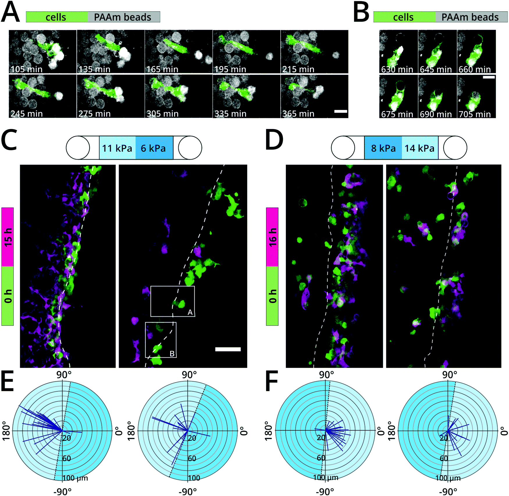 | ||
| Fig. 3 3D durotaxis of fibroblasts. NIH3T3/GFP fibroblasts migrating through PLL–Cy5 coated PAAm colloidal crystals of varying stiffness. (A and B) Representative single confocal slices of areas indicated in (C) showing fibroblasts (green) interacting with and migrating through colloidal crystals (grey) over time. Scale bars: 20 μm. (C) Overlay of maximum projections of fibroblast fluorescence signal for starting point (green, t = 0 h) and end point (magenta, t = 15 h). Channel consisting of a more compliant colloidal crystal (cT = 9.9%, mean Young's modulus: 6 kPa) on the right side and a stiff colloidal crystal (cT = 11.8%, mean Young's modulus: 11 kPa) on the left side. 20000 cells seeded. (D) Overlay of maximum projections of fibroblast fluorescence signal for starting point (green, t = 0 h) and end point (magenta, t = 16 h). Channel consisting of a stiffer colloidal crystal (cT = 11.8%, mean Young's modulus: 14 kPa) on the right side and a more compliant colloidal crystal (cT = 9.9%, mean Young's modulus: 8 kPa) on the left side. 10000 cells seeded. The two panels in (C) and (D) show two representative experiments for the same experimental condition. Scale bar: 50 μm. (E and F) Directionality analysis of migrating fibroblasts from (C) and (D), respectively. Colloidal crystal layer interfaces are marked by dashed line. Time series for (A)–(C) are available as movies in the ESI† (Movies S1–S3). | ||
Mechanosensitive dorsal root ganglion neurite outgrowth in colloidal crystals
The mechanical properties of the substrate affect different aspects of neuronal physiology and function. For example, studies on flexible 2D substrates of varying stiffness have reported differences in neurite growth including branching, dendrite arborization and network activity influenced by the substrate mechanics.33–36 Using our colloidal crystal model, it is now possible to expand these investigations into 3D microenvironments while covering physiological tissue stiffness ranges and above. Here, DRG neurons isolated from adult mice were randomly seeded in colloidal crystals of PAAm microgel beads of different stiffness (ESI,† Fig. S6) coated with poly-D-lysine and laminin. After three days in culture, the neurite outgrowth of the DRG neurons was visualized by rhodamine-phalloidin and DAPI staining for actin cytoskeleton and nuclei visualization, respectively. When exposed to compliant colloidal crystals (∼2 kPa), we observed an extensive neurite outgrowth over large distances forming complex network-like structures (Fig. 4A, D and ESI,† Movie S4). Conversely, outgrowth of neurites was visibly reduced in DRG neurons exposed to scaffolds with intermediate (∼6 kPa) and especially high stiffness (∼18 kPa) (Fig. 4B and C, see ESI,† Movies S5 and S6). In colloidal crystals with intermediate stiffness, we observed that neurite elongation appeared to be smaller and the network-like structures looked denser (Fig. 4B, D and ESI,† Movie S5), whereas very few neurites were observed in stiff colloidal crystals (Fig. 4C, D and ESI,† Movie S6).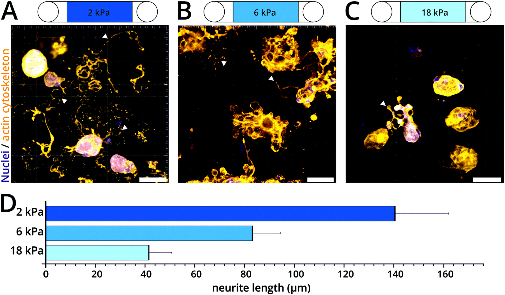 | ||
| Fig. 4 3D mechanosensitivity of DRG neurite growth. (A–C) Representative 3D confocal images of DRG neurons cultured in colloidal crystals of different stiffness coated with poly-D-lysine and laminin. After three days in culture, neurons were fixed and stained with cytoskeletal marker rhodamine-phalloidin (orange) and nuclear marker DAPI (blue). Arrowheads indicate exemplary neurite outgrowth. Scale bars: 40 μm. (A) cT = 7.9% (B) cT = 9.9% (C) cT = 13.8%. Rotating 3D views are available as movies in the ESI† (Movies S4–S6). (D) Average neurite length for each culture condition (n = 15). | ||
Discussion
In this study, we successfully developed and optimized a novel cell culture method by fabricating colloidal crystals that decouple scaffold stiffness, porosity and adhesion, and can provide two stiffness layers within one scaffold. We used PAAm microgel beads as colloidal crystal building blocks and, in combination with a three-layer filter, generated stable and regular 3D colloidal crystals by means of centrifugation. Moreover, we showed the functionality of the colloidal crystals as a 3D cell culture model and as a tool for mechanosensitivity studies. We performed a pilot experiment to study cell attachment and durotactic cell migration, as well as first 3D mechanosensitivity studies of DRG neurite outgrowth.Colloidal crystal characterization
In the last decade, advances in tissue engineering saw the use of microspheres as building blocks for 3D constructs with the aim to create highly interconnected porous scaffolds that facilitated nutrient supply to cells.19 Microsphere-based scaffolds range from purely synthetic to purely natural polymers, such as PEG,21 PEG conjugated with fibronectin and hyaluronic acid37 hyaluronic acid,22 gelatin24 or collagen-coated PAAm;38 with diameters between 70 μm and 300 μm.19 Others have used a liquid-foaming approach to create scaffolds with monodisperse uniformed circular pores and showed that fibroblast grown in 45 μm-diameter pores lose their dorsal-ventral polarity.39 Recent studies by the group of Tatiana Segura reported, for the first time, a porous microgel scaffolds with tunable stiffness for in vivo wound healing applications.21–23 They generated hyaluronic acid (HA) microgels with a diameter around 80 μm and smaller scaffold pore sizes than previously reported in porous hydrogels.22 However, using active biomaterials as building blocks has some limitations in attempts to single out the relative contribution of various scaffold material parameters, since biological materials can directly affect cell behaviour. For instance, fibroblasts migrate slower on HA hydrogels with increasing stiffness,37 while they migrate faster on collagen-coated PAAm with the same stiffness range.38 In a recent study, Sheikhi et al. aimed to decouple stiffness and bulk gel porosity by annealing gelatin-based microgel beads with varying stiffness and reported to a uniform pore diameter of 20 μm.24 Nevertheless, a drawback of the current hydrogel models is the limitation to fabricate scaffolds with internal stiffness gradients, while porosity and adhesion sites remain constant.Here, we used an inert hydrogel material with adjustable stiffness to ranges encountered in physiological conditions. Importantly, PAAm hydrogel does not influence cell behaviour or cell attachment40,41 and can be specifically functionalized with various cell ligands, such as laminin, collagen or fibronectin. An important advantage of our system is the possibility to generate scaffolds with different layers of stiffness without altering the porosity of the scaffold in principle. At the same time pore diameter can be adjusted simply by using monodisperse microgel beads of different sizes (Fig. 2E). In the present study, cells were randomly embedded into the scaffold during the assemble process. Because of this, the regularity of the scaffolds in the area of cells was sometimes slightly distorted, as cells were taking up space where beads should have been. Alternatively, more stable and perfectly regular scaffolds can be generated by microgel bead annealing after fabrication using degradable crosslinkers.21 Cells would then have to be introduced later. This approach then creates an interconnected colloidal crystal with constant porosity, even within a single scaffold, where cells can infiltrate, migrate and proliferate.
A flow channel suitable for live-cell imaging was employed and adapted to generate a 3D microgel bead scaffold. We first devised a three-layer filter with decreasing pore size that served as a stopper for the small and deformable monodisperse microgel beads, while allowing liquid to flow through. This permeable filter was useful for replacing culture medium or for downstream applications, such as immunostaining. To avoid disassembly of the colloidal crystals another stopper layer consisting of PAAm beads was introduced at the other end of the flow channel. Since material and porosity are not critical at this position, one future possibility is to introduce a stable stopper layer that can be annealed by photo-polymerization e.g., MAP gels or GelMA beads.22,24 Despite the fact that the microgels are not annealed in a mechanically stable colloidal crystal, more than 80% of the generated colloidal crystals were highly regular and therefore cells had limited space to move the beads around.
Cell migration through 3D microenvironments is often dictated by a combination of scaffold stiffness and pore size.42 Cells circumvent these physical constrains by proteolytic degradation of the scaffold to widen the migratory path, and by cell body deformation to pass through narrow pores.43,44 Whereas the cytoplasm of cells is highly compliant and can penetrate through confining pores, the nucleus is more rigid and presents a limiting factor during migration. For example cancer cells, migrating through microfluidic channel constrictions of 3 μm in diameter, exhibited massive nuclear rupture followed by DNA damage.45,46 Additionally, precise control of porosity is critical in tissue engineering and regeneration where optimal pore size varies from one cell type to another.47 In our scaffold we used microgel beads with a diameter of 15 μm (Fig. 2E), based on the findings that optimal implant pore size for fibroblasts ranges between 5–15 μm.47 One advantage of our system is that colloidal crystal pore diameter can be adjusted simply by the use of monodisperse microgel beads with different sizes (Fig. 2E), which might be necessary for different cell types. In contrast, adjusting pore size in bulk hydrogels depends on various parameters, such as hydrogel material and temperature, which might result in different microarchitectures.48
Characterization of colloidal crystals using confocal microscopy depends on the imaging quality inside the depth of the scaffold. Since the PAAm beads had a refractive index close to the aqueous medium surrounding them, light loss by scattering and diffraction and deterioration of image quality was minimized. When using other bead materials, such as PMMA, which might be desirable in certain applications, matching the refractive index of the solution in the flow chamber with the refractive index of the plastic beads is necessary. Immersing PMMA bead scaffolds in a 2,2-thiodiethanol–water solution with a refractive index of 1.488 reduced diffraction losses and increased the image signal to noise ratio and axial imaging depth (z-axis) from 80 to 400 μm (ESI,† Fig. S7 right) and overall improved image quality. It should be noted that 2,2-thiodiethanol is cytotoxic and thus not suitable for live-cell imaging.49
Oxygen
An important parameter to consider in 3D cultures is the oxygen supply, since limitations in oxygen can influence cellular behaviour such as survival, proliferation and migration.30,32 We thus used computer simulations to model the availability of oxygen and predict whether the 3D scaffolds could support cell growth. Our model assumed that cells were randomly distributed, and that oxygen was the only limitation. We assumed a direct proportionality between permeability and temperature and thus calculated permeability at 37 °C. However, the experimental influx of oxygen might be higher considering that the direct relationship between permeability and temperature is often over-proportional (i.e., it depends on the actual material).50 Moreover, in our experimental model fibroblasts formed cellular clusters upon migration that might change the resulting oxygen profile.51To avoid fluctuations in glucose levels, another limiting factor known to affect proliferation rates, the culture medium was replaced daily. Additionally, we used a low starting seeding density since at high cell densities the growth rate might be influenced by low oxygen diffusivity.52 Future simulations models could also account for cell death by implementing a step-down function.50 In addition, simulated oxygen levels can be confirmed using dispersible oxygen microsensors29 or non-invasive optical oxygen measurements51 for measuring experimental oxygen concentration in our system.
Fibroblast durotaxis
The phenomenon of fibroblast migration towards region of increasing stiffness (i.e. durotaxis) appears to be conserved in both 2D and 3D environments.1,10,11,13,53 Nevertheless, to our knowledge our study is the first to study durotaxis using scaffolds where stiffness is decoupled from simultaneous changes in pore size. To examine the performance of our scaffold we assessed the migratory behaviour of fluorescently labelled fibroblasts in scaffolds consisting of two different stiffness layers and uniform pore size. Fibroblasts exhibited durotactic behaviour and migrated towards the stiffer region of the scaffold, independent of stiffness orientation (Fig. 3C and D). This is in accordance to previous studies that showed that fibroblasts preferentially accumulate in stiffer regions, both in 2D and 3D models.1,10,54,55 This accumulation could be explained by the 3D durotactic behavior we observed for fibroblasts in our system—independent of stiffness orientation (Fig. 3C and D). Cell adhesion and growth were similar, irrespective of stiffness (Fig. 2E and ESI,† Fig. S3, S4). Slight morphological differences were observed in stiffer regions, where cells appeared to have more cell protrusions. This could be attributed to increased fibroblast spreading as previously reported.39,56 However, extensive characterization of the actin cytoskeleton and focal adhesion proteins (paxillin, talin, vinculin) is necessary to assess how cells respond and determine substrate rigidity in these 3D scaffolds.Follow-up studies will also focus on the mechanosensitivity of cells exposed to various mechanical and biochemical cues. It is possible to functionalize the microgel beads with different extracellular matrix ligands, for example fibronectin, collagen, and tenascin, and assess how cells sense and respond to this environment. A drawback of functionalizing the microgel beads at present is that the amount of bound ligand is dependent on the amount of NHS-groups incorporated in the hydrogel.41 Consequently, stiffer PAAm microgel beads contain more NHS-groups and therefore potentially more adhesive ligands,41 which could have a chemotactic effect. The relative amount of ligand bound to beads can be assessed by immunostaining and confocal microscopy; as shown for laminin-coated beads (ESI,† Fig. S8) or in the future using a serial dilution assay with fluorescently-labelled adhesion ligands. Importantly, new methods are being developed for functionalizing PAAm hydrogels with controlled densities of ligands, independent of stiffness, which will be employed in future scaffolds.57 Finally, our model could be used to generate scaffolds with multiple stiffness layers in order to approach gradient-like stiffness.
The mechanisms underlying 3D migration can differ from 2D and be independent from focal adhesions, resulting in different migration modes (mesenchymal migration vs. amoeboid migration).58–61 One such possible adhesion-independent migration mechanism is called chimneying force transmission.59 However, there is no evidence whether adhesion-independent migration can also exhibit a durotactic behaviour, as focal adhesions are thought to be one of the mechanosensing elements directing migration. In our study, fibroblasts embedded in non-functionalized beads appeared rounder, formed cell clusters (ESI,† Fig. S5) and failed to migrate to stiffer regions. Nevertheless, more work is needed to assess whether this phenomenon is caused by lack of adhesion ligands or focal adhesion complexes, or due to changes in dorsal-ventral asymmetry. Follow-up studies on amoeboid migration are also possible owing to the inert properties of the hydrogel material and the density and regularity of the scaffold. These features should permit cells to exert forces to move forward in confined spaces, independent of focal adhesions.58–60
DRG neurite outgrowth
Over the last decades it has been shown that mechanosensing of neuronal cells is important for central nervous system (CNS) development, maturation, regeneration and pathophysiology.62–64 Neuronal mechanosensitivity has been investigated in 2D,33,64 and 3D assays65 with the same drawbacks as already discussed for migration studies. It has been shown that neurite outgrowth decreases in stiffer microenvironments.33,65 The stiffness range investigated in these studies was between 50–5500 dyne per cm2, which translates to 5–550 Pa (i.e., in vivo nervous tissue stiffness) and lower than the stiffness ranges of 2–18 kPa covered in the present study. Koser and colleagues demonstrated that retinal ganglion cell axons from Xenopus laevis grew longer on stiffer 2D substrates,64 but the stiff PAAm gels used (1 kPa) were actually similar to the lower range of microgel bead stiffness utilized in our study. Our results indicate that DRG neurons extend longer neurites in physiologically compliant 3D scaffolds compared to—non-physiological—intermediate and stiff scaffolds. This result is in accordance with previous data showing that neurons have a preference for physiological, soft microenvironments.33–36 The effect of microenvironment stiffness in neuronal growth has important implications for tissue engineering strategies aimed at promoting nervous system regeneration and repair.66 It has been proposed that in the case of CNS injuries, such as spinal cord injury and the formation of a glial scar, the biochemical as well as mechanical properties of the tissue microenvironment play an important role in the process of regeneration. It has indeed been shown in the spinal cord of zebrafish larvae67 and rat brain68 that CNS stiffness changes after injury. These changes might, among other factors, be the result of an accumulation of different cells and ECM molecules within the resulting glial scar and could thus prevent the regrowth of axons also by some mechanosensitive mechanism.62,69,70 We believe that the use of 3D scaffolds, where the mechanical properties can be decoupled from biochemical parameters, constitute an important methodical advance to study the mechanosensing mechanisms of neurons and glial cells to changes in microenvironment stiffness within the same platform. Ultimately, research utilizing these scaffolds could provide a better understanding of the role that the microenvironment stiffness plays in nervous tissue regeneration.62Conclusions
We developed a novel 3D scaffold consisting of PAAm colloidal crystals where all parameters could, in principle, be decoupled from the mechanical properties of the substrate. The unique modularity of our system allows the user to functionalize the microgel beads with different ECM ligands; to adjust porosity by changing the diameter of the microbeads and to create multiple stiffness steps within the same scaffold. Ultimately, this novel 3D culture system could be used to rebuild patterns that mimic the mechanical properties of in vivo environments; such as during neuronal regeneration after injury62 or the evolution of layered retina structure during development.71 Ultimately, this novel 3D culture scaffold could uniquely establish the importance of mechanics for various biological and biomedical processes.Author contributions
K. W. designed and performed all experiments. S. G. and R. G. produced PAAm microgel beads. G. R. dissected the mice and isolated the DRG neurons. E. U. supervised the cell culture experiments. P. M. implemented the Python script for regularity analysis. N. T. performed AFM measurements and data analysis. J. G. conceived and supervised the project. K. W. and J. G. wrote the manuscript with the help of G. R and D. S. All authors reviewed the manuscript.Data availability
The raw/processed data required to reproduce these findings is available upon request.Conflicts of interest
There are no conflicts to declare.Acknowledgements
We thank the Microstructure Facility and the Light Microscopy Facility of the CMCB (both in part funded by the State of Saxony and the European Regional Development Fund), respectively, for the production of the microgel beads and for support with imaging. We thank Robert Stange and Tim Lauterbach from the Institute of Natural Materials Technology, Bioprocess Engineering, TU Dresden for their help and discussions regarding the oxygen simulations. We thank Noreen Walker and Jan Pechyl from the Max Planck Institute of Molecular Cell Biology and Genetics for their help with the NeuriteTracer in Imaris. This project was made possible by funding from the Alexander-von-Humboldt Stiftung (Humboldt-Professorship to J. G.). G. R. received funding from the German Research Foundation (DFG SH 167/9-1) and Innovative Medizinische Forschung (ROH511701). Open Access funding provided by the Max Planck Society.References
- C.-M. Lo, H.-B. Wang, M. Dembo and Y. Wang, Biophys. J., 2000, 79, 144–152 CrossRef CAS.
- D. E. Discher, D. J. Mooney and P. W. Zandstra, Science, 2009, 324, 1673–1677 CrossRef CAS PubMed.
- A. J. Engler, S. Sen, H. L. Sweeney and D. E. Discher, Cell, 2006, 126, 677–689 CrossRef CAS PubMed.
- K. Duval, H. Grover, L.-H. Han, Y. Mou, A. F. Pegoraro, J. Fredberg and Z. Chen, Physiology, 2017, 32, 266–277 CrossRef CAS PubMed.
- J. Hoarau-Véchot, A. Rafii, C. Touboul and J. Pasquier, Int. J. Mol. Sci., 2018, 19, 181 CrossRef PubMed.
- Z. Liu, M. Tang, J. Zhao, R. Chai and J. Kang, Adv. Mater., 2018, 30, 1705388 CrossRef PubMed.
- R. Edmondson, J. J. Broglie, A. F. Adcock and L. Yang, Assay Drug Dev. Technol., 2014, 12, 207–218 CrossRef CAS PubMed.
- D. Antoni, H. Burckel, E. Josset and G. Noel, Int. J. Mol. Sci., 2015, 16, 5517–5527 CrossRef CAS PubMed.
- C. Pérez-González, R. Alert, C. Blanch-Mercader, M. Gómez-González, T. Kolodziej, E. Bazellieres, J. Casademunt and X. Trepat, Nat. Phys., 2019, 15, 79–88 Search PubMed.
- E. Hadjipanayi, V. Mudera and R. A. Brown, Cell Motil. Cytoskeleton, 2009, 66, 121–128 CrossRef CAS PubMed.
- R. S. Stowers, S. C. Allen and L. J. Suggs, Proc. Natl. Acad. Sci. U. S. A., 2015, 112, 1953–1958 CrossRef CAS PubMed.
- M. W. Tibbitt and K. S. Anseth, Biotechnol. Bioeng., 2009, 103, 655–663 CrossRef CAS PubMed.
- M. Miron-Mendoza, J. Seemann and F. Grinnell, Biomaterials, 2010, 31, 6425–6435 CrossRef CAS PubMed.
- J. Shan, Q. Chi, H. Wang, Q. Huang, L. Yang, G. Yu and X. Zou, Cell Biol. Int., 2014, 38, 1233–1243 CrossRef CAS PubMed.
- N. A. Kotov, Y. Liu, S. Wang, C. Cumming, M. Eghtedari, G. Vargas, M. Motamedi, J. Nichols and J. Cortiella, Langmuir, 2004, 20, 7887–7892 CrossRef CAS PubMed.
- O. D. Velev and A. M. Lenhoff, Curr. Opin. Colloid Interface Sci., 2000, 5, 56–63 CrossRef CAS.
- J. da Silva, F. Lautenschläger, E. Sivaniah and J. R. Guck, Biomaterials, 2010, 31, 2201–2208 CrossRef CAS PubMed.
- S. Pautot, C. Wyart and E. Y. Isacoff, Nat. Methods, 2008, 5, 735–740 CrossRef CAS PubMed.
- V. Gupta, Y. Khan, C. J. Berkland, C. T. Laurencin and M. S. Detamore, Annu. Rev. Biomed. Eng., 2017, 19, 135–161 CrossRef CAS PubMed.
- A. W. Smith, C. E. Segar, P. K. Nguyen, M. R. MacEwan, I. R. Efimov and D. L. Elbert, Acta Biomater., 2012, 8, 31–40 CrossRef CAS PubMed.
- D. R. Griffin, W. M. Weaver, P. O. Scumpia, D. Di Carlo and T. Segura, Nat. Mater., 2015, 14, 737–744 CrossRef CAS PubMed.
- E. Sideris, D. R. Griffin, Y. Ding, S. Li, W. M. Weaver, D. Di Carlo, T. Hsiai and T. Segura, ACS Biomater. Sci. Eng., 2016, 2, 2034–2041 CrossRef CAS.
- L. R. Nih, E. Sideris, S. T. Carmichael and T. Segura, Adv. Mater., 2017, 29, 1606471 CrossRef PubMed.
- A. Sheikhi, J. de Rutte, R. Haghniaz, O. Akouissi, A. Sohrabi, D. Di Carlo and A. Khademhosseini, Biomaterials, 2019, 192, 560–568 CrossRef CAS PubMed.
- S. Girardo, N. Träber, K. Wagner, G. Cojoc, C. Herold, R. Goswami, R. Schlüßler, S. Abuhattum, A. Taubenberger, F. Reichel, D. Mokbel, M. Herbig, M. Schürmann, P. Müller, T. Heida, A. Jacobi, E. Ulbricht, J. Thiele, C. Werner and J. Guck, J. Mater. Chem. B, 2018, 6, 6245–6261 RSC.
- M. Glaubitz, N. Medvedev, D. Pussak, L. Hartmann, S. Schmidt, C. A. Helm and M. Delcea, Soft Matter, 2014, 10, 6732 RSC.
- J. Schindelin, I. Arganda-Carreras, E. Frise, V. Kaynig, M. Longair, T. Pietzsch, S. Preibisch, C. Rueden, S. Saalfeld, B. Schmid, J.-Y. Tinevez, D. J. White, V. Hartenstein, K. Eliceiri, P. Tomancak and A. Cardona, Nat. Methods, 2012, 9, 676–682 CrossRef CAS PubMed.
- L. E. Smart and E. A. Moore, Solid State Chemistry: An Introduction, CRC Press, 4th edn, 2012 Search PubMed.
- A. Colom, R. Galgoczy, I. Almendros, A. Xaubet, R. Farré and J. Alcaraz, J. Biomed. Mater. Res., Part A, 2014, 102, 2776–2784 CrossRef PubMed.
- M. Csete, Ann. N. Y. Acad. Sci., 2005, 1049, 1–8 CrossRef CAS PubMed.
- S. C. Lesher-Pérez, G.-A. Kim, C. Kuo, B. M. Leung, S. Mong, T. Kojima, C. Moraes, M. D. Thouless, G. D. Luker and S. Takayama, Biomater. Sci., 2017, 5, 2106–2113 RSC.
- W. G. Taylor, R. F. Camalier and K. K. Sanford, J. Cell. Physiol., 1978, 95, 33–40 CrossRef CAS PubMed.
- L. A. Flanagan, Y.-E. Ju, B. Marg, M. Osterfield and P. A. Janmey, NeuroReport, 2002, 13, 2411–2415 CrossRef PubMed.
- P. C. Georges, W. J. Miller, D. F. Meaney, E. S. Sawyer and P. A. Janmey, Biophys. J., 2006, 90, 3012–3018 CrossRef CAS PubMed.
- M. L. Previtera, C. G. Langhammer, N. A. Langrana and B. L. Firestein, Ann. Biomed. Eng., 2010, 38, 3733–3743 CrossRef PubMed.
- Q.-Y. Zhang, Y.-Y. Zhang, J. Xie, C.-X. Li, W.-Y. Chen, B.-L. Liu, X. Wu, S.-N. Li, B. Huo, L.-H. Jiang and H.-C. Zhao, Sci. Rep., 2015, 4, 6215 CrossRef PubMed.
- K. Ghosh, Z. Pan, E. Guan, S. Ge, Y. Liu, T. Nakamura, X.-D. Ren, M. Rafailovich and R. A. F. Clark, Biomaterials, 2007, 28, 671–679 CrossRef CAS PubMed.
- F. Liu, J. D. Mih, B. S. Shea, A. T. Kho, A. S. Sharif, A. M. Tager and D. J. Tschumperlin, J. Cell Biol., 2010, 190, 693–706 CrossRef CAS PubMed.
- Y. Lee, J. Huang, Y. Wang and K. Lin, Integr. Biol., 2013, 5, 1447 CrossRef CAS PubMed.
- E. G. Richards and C. J. Temple, Nat. Phys. Sci., 1971, 230, 92–96 CrossRef CAS.
- C. E. Kandow, P. C. Georges, P. A. Janmey and K. A. Beningo, Methods in Cell Biology, 2007, vol. 83, pp. 29–46 Search PubMed.
- J. da Silva, F. Lautenschläger, C.-H. R. Kuo, J. Guck and E. Sivaniah, Integr. Biol., 2011, 3, 1202–1206 CrossRef CAS PubMed.
- P. Friedl, K. Wolf and J. Lammerding, Curr. Opin. Cell Biol., 2011, 23, 55–64 CrossRef CAS PubMed.
- J. Guck, F. Lautenschläger, S. Paschke and M. Beil, Integr. Biol., 2010, 2, 575–583 CrossRef PubMed.
- S. J. Riedl and G. S. Salvesen, Nat. Rev. Mol. Cell Biol., 2007, 8, 405–413 CrossRef CAS PubMed.
- C. M. Denais, R. M. Gilbert, P. Isermann, A. L. McGregor, M. te Lindert, B. Weigelin, P. M. Davidson, P. Friedl, K. Wolf and J. Lammerding, Science, 2016, 352, 353–358 CrossRef CAS PubMed.
- S. Yang, K.-F. Leong, Z. Du and C. Chua, Tissue Eng., 2001, 7, 679–689 CrossRef CAS PubMed.
- N. Annabi, J. W. Nichol, X. Zhong, C. Ji, S. Koshy, A. Khademhosseini and F. Dehghani, Tissue Eng., Part B, 2010, 16, 371–383 CrossRef CAS PubMed.
- T. Staudt, M. C. Lang, R. Medda, J. Engelhardt and S. W. Hell, Microsc. Res. Tech., 2007, 70, 1–9 CrossRef CAS PubMed.
- E. Baur, S. Brinkmann, T. A. Osswald, N. Rudolph and E. Schmachtenberg, Saechtling Kunststoff Taschenbuch, Carl Hanser Verlag GmbH & Co. KG, München, 2013 Search PubMed.
- P. Buchwald, Theor. Biol. Med. Modell., 2009, 6, 5 CrossRef PubMed.
- T. I. Croll, S. Gentz, K. Mueller, M. Davidson, A. J. O’Connor, G. W. Stevens and J. J. Cooper-White, Chem. Eng. Sci., 2005, 60, 4924–4934 CrossRef CAS.
- D. J. Tschumperlin, Physiology, 2013, 28, 380–390 CrossRef CAS PubMed.
- B. C. Isenberg, P. A. DiMilla, M. Walker, S. Kim and J. Y. Wong, Biophys. J., 2009, 97, 1313–1322 CrossRef CAS PubMed.
- D. S. Gray, J. Tien and C. S. Chen, J. Biomed. Mater. Res., Part A, 2003, 66, 605–614 CrossRef PubMed.
- J. Solon, I. Levental, K. Sengupta, P. C. Georges and P. A. Janmey, Biophys. J., 2007, 93, 4453–4461 CrossRef CAS PubMed.
- A. Farrukh, J. I. Paez, M. Salierno, W. Fan, B. Berninger and A. del Campo, Biomacromolecules, 2017, 18, 906–913 CrossRef CAS PubMed.
- M. Bergert, A. Erzberger, R. A. Desai, I. M. Aspalter, A. C. Oates, G. Charras, G. Salbreux and E. K. Paluch, Nat. Cell Biol., 2015, 17, 524–529 CrossRef CAS PubMed.
- E. K. Paluch, I. M. Aspalter and M. Sixt, Annu. Rev. Cell Dev. Biol., 2016, 32, 469–490 CrossRef CAS PubMed.
- M. Sixt, J. Cell Biol., 2012, 197, 347–349 CrossRef CAS PubMed.
- R. J. Petrie and K. M. Yamada, Trends Cell Biol., 2015, 25, 666–674 CrossRef CAS PubMed.
- K. Franze, P. A. Janmey and J. Guck, Annu. Rev. Biomed. Eng., 2013, 15, 227–251 CrossRef CAS PubMed.
- P. Moshayedi, G. Ng, J. C. F. Kwok, G. S. H. Yeo, C. E. Bryant, J. W. Fawcett, K. Franze and J. Guck, Biomaterials, 2014, 35, 3919–3925 CrossRef CAS PubMed.
- D. E. Koser, A. J. Thompson, S. K. Foster, A. Dwivedy, E. K. Pillai, G. K. Sheridan, H. Svoboda, M. Viana, L. D. F. Costa, J. Guck, C. E. Holt and K. Franze, Nat. Neurosci., 2016, 19, 1592–1598 CrossRef CAS PubMed.
- A. P. Balgude, X. Yu, A. Szymanski and R. V. Bellamkonda, Biomaterials, 2001, 22, 1077–1084 CrossRef CAS PubMed.
- S. P. Lacour, G. Courtine and J. Guck, Nat. Rev. Mater., 2016, 1, 16063 CrossRef CAS.
- R. Schlüßler, S. Möllmert, S. Abuhattum, G. Cojoc, P. Müller, K. Kim, C. Möckel, C. Zimmermann, J. Czarske and J. Guck, Biophys. J., 2018, 115, 911–923 CrossRef PubMed.
- E. Moeendarbary and A. R. Harris, Wiley Interdiscip. Rev.: Syst. Biol. Med., 2014, 6, 371–388 Search PubMed.
- J. W. Fawcett and R. Asher, Brain Res. Bull., 1999, 49, 377–391 CrossRef CAS PubMed.
- J. Silver and J. H. Miller, Nat. Rev. Neurosci., 2004, 5, 146–156 CrossRef CAS PubMed.
- R. Amini, M. Rocha-Martins and C. Norden, Front. Neurosci., 2018, 11, 1–16 Search PubMed.
Footnote |
| † Electronic supplementary information (ESI) available. See DOI: 10.1039/c9sm01226e |
| This journal is © The Royal Society of Chemistry 2019 |