 Open Access Article
Carbon fibre based flexible piezoresistive composites to empower inherent sensing capabilities for soft actuators†
Xue
Yan
ab,
Chris R.
Bowen
a,
Chenggang
Yuan
a,
Zhe
Hao
a and
Min
Pan
 *a
*a
aDepartment of Mechanical Engineering, University of Bath, Bath, BA2 7AY, UK. E-mail: m.pan@bath.ac.uk
bScience and Technology on Advanced Functional Composites Laboratory Aerospace Research Institute of Material and Processing Technology, Beijing 100076, P. R. China
First published on 23rd August 2019
Abstract
New materials and technologies in sensing and actuation have led to the development of soft actuators and robots for biomedical systems, assistive devices, exploration and rescue. The use of integrated actuation-sensing materials in such systems is gaining interest, but there are few examples where the body of the actuator or soft robot acts as the sensing element. The development of smart soft actuators that have inherent sensing capabilities can provide advantages of high sensitivity, ease of manufacture and cost efficiency, without impairing actuator dynamics. To achieve this goal, we have prepared soft actuators using piezoresistive composites based on a silicone matrix impregnated with short conductive carbon fibres. The optimum carbon fibre volume fraction to achieve a frequency independent conductivity and piezoresistive response was determined, with in situ mechanical and electrical testing to quantify the piezoresistive properties. The frequency dependent electrical properties and sensitivity of the composites with deformation was explained on the basis of a microstructural resistor–capacitor network model. The piezoresistive composites were used to successfully manufacture a pneumatic soft finger actuator where the resistance change of the actuator body was able to monitor deformation with applied pressure. The creation of soft actuators with an inherent sensing capability is a promising approach for control and operation of future soft robots.
Introduction
Soft robotics is an emerging area where there are a number of key challenges that are pushing the boundaries of robotic technologies to provide soft movement and control of robots, actuation with multiple degrees of freedom and safe interaction of robots with humans. Within the area soft robotics, fundamental biological principles have been exploited and converted into engineering design rules to create robots that perform in a similar manner to natural animals, where the elasticity of soft bodies matches the compliance of animal muscle. The soft robotics approach has been used to build integrated systems for applications that include biomedical devices,1 surgical instruments,2 rehabilitation systems,3 assistive devices,4,5 and robotics for exploration and rescue.6Significant progress in the development and advancement of soft actuators and robots has been achieved in the last decade to achieve flexibility, adaptability, ease of manufacture and low-cost processing.7 However, to attain their full potential the key technologies of materials, sensing, and actuation must be effectively integrated and operate cooperatively. Therefore, technologies that couple both sensing and actuation are critical to accelerate the design and implementation of future soft robots.8,9
There has been significant effort to embed sensors in robotic systems to provide improved control and feedback. Ozel et al. designed a novel curvature sensor to measure the bending of soft bodies using a magnet and a Hall effect sensor. The sensor was embedded in a soft snake robot which exhibited a root mean square error of 0.023 cm−1 between the measured and actual curvature at frequencies up to 7.5 Hz.10 Piezoresistive micro-electro-mechanical-systems (MEMS) have also been considered as sensors, based on fabricating and embedding individual tactile sensing elements.11 Yang et al. fabricated pressure and position sensors which were embedded in a gripper for force measurement and closed-loop control.12 Sensing rigid fingernails were used by Morrow et al. which integrated microfluidic sensors in a pneumatic actuator to measure curvature and applied force.13
In addition to embedding sensor devices, there have been approaches to embed materials with sensing capability. Yeo et al. embedded a flexible strain sensor into a soft pneumatic actuator, which also included air micro-channels to provide actuation. The strain sensor consisted of screen-printed silver nanoparticles on an elastomeric substrate to achieve mechanical flexibility,14 which was used in a rehabilitation glove to measure strains above 20% and detect irregular finger movements. An embedded 3D printing method (e-3DP) was proposed by Muth et al. to fabricate strain sensors within extensible elastomeric matrices.15 The strain sensors were printed within a pre-moulded, glove-shaped reservoir for real time monitoring of digit motion. The highly stretchable sensors were based on 3D printing a carbon-based resistive ink within an elastomeric matrix. Park et al. fabricated a flexible and stretchable artificial skin based on multi-layered micro-channels in an elastomer matrix filled with a conductive liquid to allow measurement of multi-axial strains and contact pressure.16 The robust sensor could measure a strain of ∼250% and was integrated into soft wearable robots and human–robot interaction devices.17,18 The formation of micro-scale surface features between flexible surfaces has also been examined to tailor the piezoresistive properties.19 More recently, Thuruthel et al.20 used embedded soft resistive sensors and addressed the challenges of sensor design, non-linearity, placement, and fabrication using a bioinspired sensory architecture and machine learning.
In terms of potential sensing mechanisms, a detailed overview of flexible and tactile sensing has been provided in key reviews21–26 where a variety of sensing mechanisms have been used such as piezoresistance (a change in resistance with stress), piezocapacitive (a change in capacitance with stress), and piezoelectric (voltage or charge generation with stress). With regard to piezoresistive sensing, these materials are often based on conductive materials embedded in an insulating matrix which leads to a change in electrical conductivity with stress or strain. As an example, Canavese et al. reported on a piezoresistive composite for a flexible and robust tactile sensor,27 where spiky conductive nickel particles were embedded into a silicone matrix. Carbon based conductive have also been used.28 For example, Wang et al. examined polymer composite sensing skins based on carbon nanotubes positioned between latex.29 Khalili et al. examined a polypyrrole based hydrogel combined with carbon nanotubes or graphene to create piezoresistive skins, where modelling was used to examine the dc conductivity change of the composite system.30 A variety of other conductors and materials have been used to form piezoresistive composites, such as MXene,31 liquid metal,32 and even combining conductors with shear stiffening polymers for potential high impact applications.33 High aspect ratio carbon nanotubes have been used to achieve a reversible change in electrical conductivity with stress of strain.34
While much of the research above has examined embedding sensor devices or materials into a component, less work has aimed to create soft actuators and robots with an inherent sensing capability, namely the device itself is manufactured from the sensing material. We therefore present a new approach, which is to manufacture the body of a soft actuator using a piezoresistive composite material and demonstrate its ability to provide information on deflection and actuation of pneumatic soft finger actuators. The development of smart soft actuators that have inherent sensing capabilities can offer the advantages of high sensitivity, ease of manufacture and cost efficiency, without impairing actuator dynamics.
Frequency dependent AC conductivity and phase angle of composites
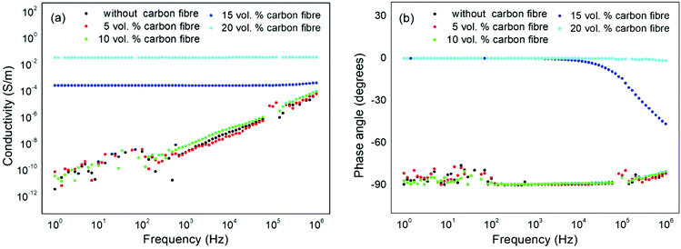
To create the flexible piezoresistive composite material, short carbon fibres (mean diameter 3.55 μm and length 105 μm35) were combined with a silicone rubber and co-cured with carbon volume fractions of 0 to 20 vol%. The silicone material has been previously used to create soft robots due to its high compliance;26 however it is an electrical insulator and has no inherent sensing properties. The aim here is to add sufficient conductive filler to the silicone to achieve percolation as a result of intimate contact of the conductive filler material. For such a material a change in electrical resistance with strain is expected due to a change in the degree of filler contact with deformation. Additional challenges to achieve inherent sensing are (i) that the composite material must remain manufacturable and can be moulded into a soft actuator by conventional moulding and (ii) that the addition of a filler does not reduce the compliance of the actuator body and thereby impair actuator performance and dynamics.The frequency dependent AC conductivity (eqn (1)) and phase angle (eqn (2)) of the manufactured composites are shown in Fig. 1(a) and (b), respectively. The sample dimensions are rectangular in shape, 60 mm × 9 mm × 1.4 mm. This geometry was selected to provide sufficient sample area for capacitance and conductivity characterisation by impedance spectroscopy and ease of electrical connectivity during mechanical deformation. For the pure silicone (0 vol%) and composites containing only 5 vol% and 10 vol% carbon fibre, the AC conductivity is frequency dependent and increases with increasing frequency. This is a result of the composite materials acting as an electrical insulator (dielectric), since the AC conductivity (σac) of a capacitor follows σac ∝ ωC; where ω is the angular frequency and C is capacitance. This insulating response leads to an almost linear dependence of AC conductivity with frequency in Fig. 1(a). This capacitive response can also be observed in Fig. 1(b), where the phase angle approaches θ ∼ −90°, since the AC current lags the AC voltage by 90° in a perfect capacitor.
For a composite with a higher fraction of carbon fibre, 15 vol%, the AC conductivity is almost frequency independent, see Fig. 1(a). The origin of the frequency independent conductivity originates from the composite material now acting as a conductor with a constant conductivity given by σac ∝ R−1, where R is resistance. The phase angle of the composite with 15 vol% also approaches θ ∼ 0° at low frequencies, since for a perfect resistor both current and voltage are in phase. It is of interest to note that phase angle for the 15 vol% composite decreases to θ ∼ −60° at higher frequencies (>104 Hz) due to a capacitive contribution to the dielectric response, see Fig. 1(b), and the reason for this will be discussed later in the paper.
For the composite with the highest volume fraction of carbon fibre, 20 vol%, the ac conductivity is frequency independent and the phase angle approaches θ ∼ 0° across the whole frequency range (10 to 106 Hz), demonstrating that this composite is acting as a good electrical conductor due to the high carbon fibre content. The higher AC conductivity of this material, compared to 15 vol%, is related to the higher volume fraction of conductive carbon fibres. Higher carbon fibre volume fractions could not be fabricated since the resulting material was too viscous for moulding into samples of the desired geometry.
Morphology and carbon fibre distribution in carbon fibre/silicone composites
The resulting microstructure and distribution of conductive carbon fibres within the insulating silicone matrix was examined using scanning electron microscopy (SEM) on a cryo-fractured sample surface, as seen in Fig. 2. The SEM image in Fig. 2(a) shows a composite containing 5 vol% carbon fibre, where it can be seen that the carbon fibres are isolated and are non-percolated. Such a distribution does not lead to electrical short circuits through the thickness of the composite which therefore acts as an insulator; this is also in agreement with the electrical measurements in Fig. 1. As the volume fraction of carbon fibres in the composite increases, the carbon fibres begin to make electrical contact with each other. This can be seen in Fig. 2(b) for the composite containing 15 vol% of carbon fibres where a number of carbon fibres are in contact with each other. For the composite containing the maximum carbon fibre content of 20 vol% in Fig. 2(c), there is a high degree of filler percolation, which results in the material behaving as a conductor, as in Fig. 1.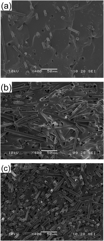 | ||
| Fig. 2 Cryo-fracture surface carbon fibre/silicone composites containing carbon fibre (a) 5 vol%, (b) 15 vol% and (c) 20 vol%. | ||
Electrical properties under mechanical stretching to assess piezoresistance
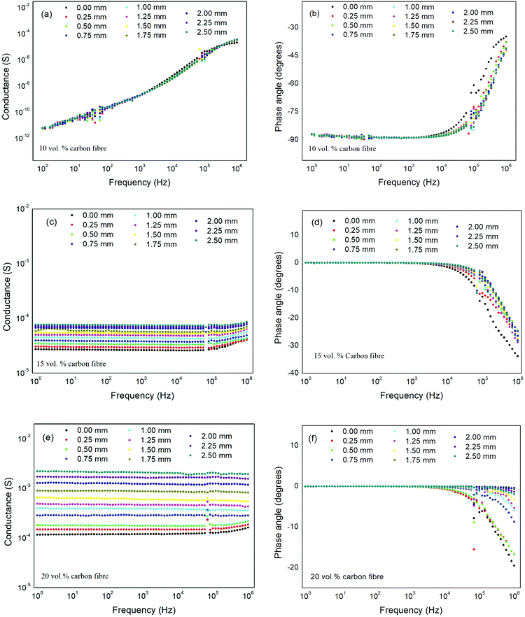
To examine the piezoresistive properties of the composite and assess its performance as a strain sensor, the frequency dependent electrical properties (AC conductivity and phase) as a function of strain was characterised. This was achieved by taking electrical measurements of the composite materials while being subjected to a tensile strain in a mechanical test machine. Composites were placed in a Hounsfield test machine with electrical connections attached to the upper and lower surface of the sample with a small bead of conductive epoxy. The electrode along the gauge length of the sample was then formed via a conductive carbon grease which was able to act successfully as an electrode during the application of a high strain (>10%); which is typical of the strain levels experienced by a soft pneumatic actuator.36,37Fig. 3 shows a variation in conductance and phase angle with frequency as a function of mechanical strain for composites with 10 vol%, 15 vol% and 20 vol% of carbon fibre. The conductance (Yac; eqn (3)) is used here, rather than conductivity (σac; eqn (1)) since changes in the area and thickness of the sample during stretching are unknown. It is of interest to note that while the conductance is dependent on sample geometry (area and thickness), the phase angle is independent of sample geometry and on the ratio of imaginary and real impedance (eqn (2)). The phase angle therefore provides an insight on only the changes in electrical properties due to changes in composite microstructure (e.g. degree of contact of carbon fibres) during deformation, while the conductance is influenced by changes in both composite microstructure and sample geometry (area and thickness).
For the composite with 10 vol% carbon fibre, the conductance does not vary significantly with strain, Fig. 3(a), and is frequency dependent. The phase angle approaches θ ∼ −90° at frequencies below 104 Hz, Fig. 3(b). In this composite, the fibres are electrically isolated, and the composite acts as an insulator, as seen in Fig. 1, and there is no piezoresistive response.
As the carbon fibre content increases to 15 vol% carbon fibre, the material behaves as a conductor with an almost frequency independent conductance which increases with increasing tensile deformation, see Fig. 3(c). This is primarily due to a combination of an increase in the connectivity of carbon fibres in the thickness direction as the material in stretched and the change in dimensions of the composite with strain, with the material thickness decreasing and area increasing with degree of stretch. Fig. 3(d) shows a phase angle θ ∼ 0° below 104 Hz due to the conductive nature of the material.
A similar response in observed for the composite with 20 vol% carbon fibre, although the composite exhibits a higher conductance and also a larger change in conductance with strain, Fig. 3(e), indicating that the increase in carbon fibre contact during stretching dominates the change in electrical properties. This can also be observed in Fig. 3(f) since the phase angle approaches θ ∼ 0° for the stretched composite, even up to high frequencies (1 MHz).
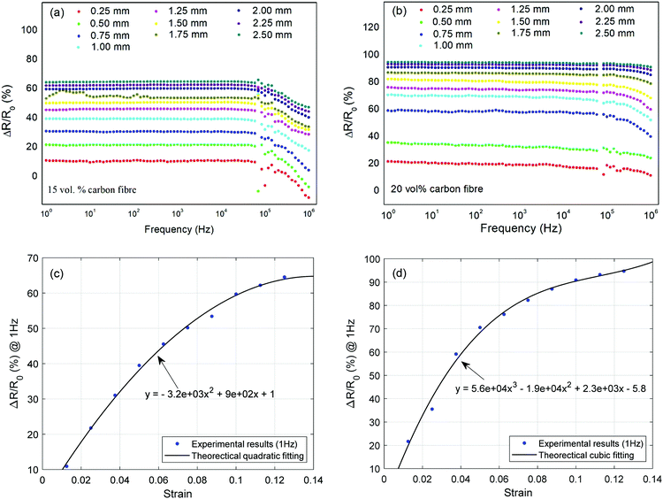
The relative resistance (eqn (4)), which provides an indication of the sensitivity of the material, of the composite containing 15 vol% reaches  when deformed up to 2.5 mm, Fig. 4(a) while the sensitivity of the 20 vol% carbon fibre material reaches
  when deformation up to 2.5 mm, Fig. 4(b). Fig. 4c and d shows the relationship between the strain and percentage resistance change
  at a fixed frequency of 1 Hz. Quadratic and cubic fitting curves were used to predict the trend which shows that the strain sensing materials becomes more conductive at higher deformation levels. The fitting curves also provide simple models which can be used to predict the relationship between the strain and relative resistance of the 15 vol% and 20 vol% fabricated piezoresistive composites.
Fig. 5 shows the force–displacement response and cyclic variation of resistance of a carbon fibre/silicone composite. The material was subjected to a cyclic strain using an Instron 3369 with a 50 N static load cell and pneumatic clamps with a small tensile load and a cyclic deformation of 2 mm at a cross head speed of 2 mm min−1. Data are shown here for the carbon fibre/silicone composite containing 15 vol% carbon fibre on a rectangular test piece with a dimension of 60 mm × 9 mm × 1.4 mm. Some hysteresis is observed which is typical of an elastomer material and the force–displacement of the composite leads to a cyclical change in resistance of the composite.
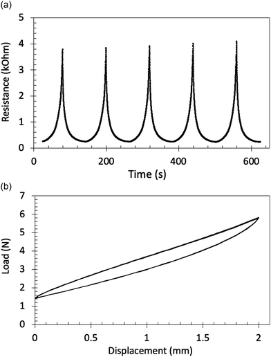 | ||
| Fig. 5 Cyclic response of (a) resistance–time (b) load–displacement during cyclic testing for a carbon fibre/silicone composite with 15 vol% carbon fibre. | ||
Mechanism of piezoresistance in composites
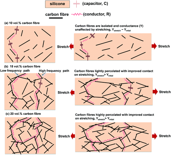
Based on the piezoresistive response and microstructural characterisation of the composites we can now put forward a mechanism to understand the piezoresistivity and frequency dependent properties of the carbon fibre/silicone composite. We consider the composite and as a random resistor–capacitor (R–C) network,38 where the resistors (R) in the network represents the conductive carbon fibres which have a frequency independent conductance (Yac = R−1) and the capacitor (C) represents the capacitive silicone matrix phase with a frequency dependent conductance (Yac ∝ ωC).For the carbon fibre/silicone composite with 5 vol% and 10 vol% carbon fibre, the electrical network of the composite structure consists of isolated (non-percolated) carbon fibres (which acts as the resistor, R) in a silicone matrix (which acts as the capacitor, C). A schematic is shown in Fig. 6(a), which represents Fig. 2(a), where at low frequencies the AC conductance is dominated by the insulating silicone regions which act as a capacitor of low conductance, especially at low frequencies. No significant changes in conductance and phase angle are observed with strain since the material is dominated by the insulating capacitive regions.
Fig. 6(b) shows a schematic of the structure of a carbon fibre/silicone composite with 15 vol% carbon fibre where in this case there is some percolation of the carbon fibres, see also Fig. 2(b). At low frequencies, the AC currents flow preferentially through the percolated carbon fibres since R−1 > ωC and the phase angle approaches 0°; see Fig. 3(d). An example of a low frequency conduction path due to percolated resistors is shown in Fig. 6(b). As the material is deformed and aligned in the direction of strain, the thickness of the composite will decrease, and the carbon fibres will make better contact in the thickness direction, which increases its conductance. At higher frequencies the AC conductivity of the capacitive regions increases and when ωC ≥ R−1, the capacitive silicone regions also contribute to the AC currents so that the phase angle decreases with increasing frequency and begins to approach −90°, Fig. 3(d). An example of the conduction path at these higher frequencies is also shown in Fig. 6(b) which is a combination of resistors (carbon fibres) and capacitors (silicone rich regions). It is of interest to note that in this high frequency region there is a decrease in the relative resistance and sensitivity, see Fig. 4(a), since the silicone contributes to the AC conduction path and does not contribute to the piezoresistance of the material.
A schematic of the carbon fibre/silicone composite with 20 vol% carbon fibre is shown in Fig. 6(c), where in this case the carbon fibres are highly percolated; see also Fig. 2(c). Again, at low frequencies the AC currents flow through the highly connected carbon fibres since R−1 > ωC, and the phase angle approaches 0° (see Fig. 3(e) and (f)). As the material is deformed and aligned in the direction of strain, the thickness of the composite decreases, and more carbon fibres connect in the thickness direction; as a result, the conductance is increased for the strained material. Due to the high degree of carbon contact during the application of strain and the high value of R−1, higher frequencies are required before ωC ≥ R−1 and the phase angle begins to fall; see Fig. 3(f). For high levels of strain the phase angle remains θ ∼ 0° up to the maximum frequency of 1 MHz, indicating the percolated carbon fibre paths dominate the conduction path in the complete frequency range; the relative resistance is also less frequency dependent compared to the 15 vol% composite for the same reason, see Fig. 4(b).
Fabrication of a soft finger with inherent sensing ability
Based on understanding that 15 vol% or 20 vol% carbon fibre in a silicone matrix creates a piezoresistive composite, we now fabricate a soft pneumatic finger actuator using the same material. Fig. 7 shows the process to fabricate the integrated soft finger and Fig. S1 (ESI†) shows the moulding and unmoulding processes of the soft finger. The moulds for composite finger casting were fabricated using a commercial 3D printer (Ultimaker 2+) using polylactic acid (PLA) which include two sections: the first section was for moulding a wax core mould; the second section is for moulding the wall of the finger. Paraffin wax (Materialix) was poured into the first section to create a wax-made core that formed the air chamber inside the finger. After mixing and degassing, two components of E630 silicone rubber (Shenzhen Hong Ye Jie Technology Co., Ltd) and carbon fibre were mixed (22.8 g carbon fibre and 77.2 g mixture per 100 g, corresponding to 15 vol% carbon fibre) and poured into the second section. This volume fraction was selected since it provided the best combination of a sufficiently low viscosity to infill the mould while also maintaining a piezoresistive response. The wax-made core was then placed into the second section after the mixture fully filled the mould. The mixture was cured at 45 °C for 60 min, then submerged into the hot water (>90 °C) in order to melt the wax core and form the air chamber. The soft inherent sensing body was then removed from the moulds after cooling to room temperature. A silicone tube was then attached to the vent hole of the actuator body using silicone adhesive (Smooth-On, Sil-Poxy). | ||
| Fig. 7 Fabrication of an integrated soft finger with inherent sensing ability. Actuator length is ∼69 mm for scale. | ||
Soft finger actuator testing
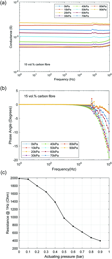
The soft finger was actuated by an air compressor (9.6 CFM, 0–10 bar, Wolf Sioux) and the actuation pressure was measured by a pressure gauge (CYYZ11, Star Sensors). The experimental setting-up for the measurement is shown in Fig. S2 (ESI†). The length of the soft finger was 69 mm, and the distance between the electrodes A and B for characterisation of electrical resistance was 50 mm.Fig. 8a and b shows a variation in ac conductance and phase angle of the soft finger with frequency as a function of actuation pressure respectively. The conductance is dependent on actuation pressure, while the phase angle is independent of pressure at low frequencies (<104 Hz) and θ ∼ 0° due to AC currents always flowing through the percolated of conductive filler in this frequency range, where R−1 > ωC. This response is similar to the test materials, Fig. 3, indicating that the soft finger is operating as an actuator with inherent sensing capability. The change in low frequency resistance (1/Yac) with pressure varies from ∼2 kΩ at low pressure to ∼400 Ω at the highest pressure, as shown in Fig. 8c at a fixed frequency of 1 Hz. The resistance range also provides the advantage of ease of measurement by using two-wire DC measurement, which is suitable for measuring resistances in excess of 100 Ω.
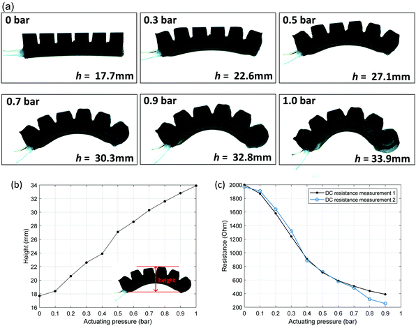
While the impedance spectroscopy data in Fig. 8 provides an examination of the frequency dependent real and imaginary impedance of the soft finger during actuation, for soft actuator or robot applications it would be beneficial to simplify the measurement approach for both speed and ease of control. A DC resistance measurement is applied in a real-time control system to acquire the measured resistance, as shown in Fig. S2 (ESI†). The measured deformation height of the actuator with pressure is shown in Fig. 9a and b. The resistance change between the two electrodes was characterised when the soft finger was actuated by varying the pressure from 0 bar to 1 bar (0.1 MPa) with a pressure step of 0.1 bar (0.01 MPa). The resistance between electrodes A and B was measured, as shown in Fig. 9c, where the results are reproducible and approximately linear relationships were achieved. The result indicates that the finger actuator itself is operating as an inherent strain sensor that can exploit a simple resistance measurement. The actuator has high compliance for soft robot applications and the use of carbon fibre as filler continues to provide high levels of deformation, as in Fig. 9a.
In summary, this paper has demonstrated a new approach to create soft actuators or robots with an inherent sensing capability where the component is manufactured from a material that acts as a sensor of stress or strain to provide information on actuator deflection and actuation. To achieve this goal, we have prepared soft actuators using piezoresistive composites based on a silicone matrix impregnated with short conductive carbon fibres, whose electrical resistance decreases with tensile strain due to improved contact between the conductive filler. The optimum carbon fibre volume fraction to achieve a frequency independent conductive response was determined, which was the result of percolation and intimate contact of the conductive filler. Combined mechanical and electrical testing revealed that composites with at least 15 vol% carbon fibre acted as piezoresistive sensors. The frequency dependent electrical properties with strain was explained using a microstructural resistor–capacitor network model, which provided insights into the variation of conductance, phase angle, piezoresistive sensitivity of the composites with both frequency and strain. The electrical resistance range of the actuator, in excess of 100 Ω, also provides the advantage of ease of measurement using a two-wire DC measurement.
The piezoresistive composites were used to successfully manufacture a pneumatic soft finger actuator where the change in resistance of the actuator was used to monitor deformation with applied pressure. In addition, the composite skin did not significantly influence the ability of the actuator to undergo large deformations. The development of smart soft actuators that have inherent sensing capabilities could offer the advantages of high sensitivity, ease of manufacture and cost efficiency, without impairing actuator dynamics and is a promising approach for control and operation of future soft robots. Potential future directions are the use of multiple electrodes to provide information of multi-axial deformation, and ultimately determine actuator shape, potential to extract strain-rates, and the use of multifunctional composites to create soft actuators or robots capable of sensing additional parameters such as pressure, displacement, speed, temperature, magnetic fields and moisture.
Experimental methods
Preparation of carbon fibre/silicone composite
In order to manufacture the piezoresistive composites, chopped carbon fibre (mean diameter 3.55 μm and length 105 μm35) was combined with the individual components of a silicone rubber (E630 silicone rubber; Shenzhen Hong Ye Jie Technology Co., Ltd) and mixed with volume ratio of 0–0.5![[thin space (1/6-em)]](https://www.rsc.org/images/entities/char_2009.gif) :
:![[thin space (1/6-em)]](https://www.rsc.org/images/entities/char_2009.gif) 1
1![[thin space (1/6-em)]](https://www.rsc.org/images/entities/char_2009.gif) :
:![[thin space (1/6-em)]](https://www.rsc.org/images/entities/char_2009.gif) 1 of (carbon fibre)
1 of (carbon fibre)![[thin space (1/6-em)]](https://www.rsc.org/images/entities/char_2009.gif) :
:![[thin space (1/6-em)]](https://www.rsc.org/images/entities/char_2009.gif) (part A silicone)
(part A silicone)![[thin space (1/6-em)]](https://www.rsc.org/images/entities/char_2009.gif) : (part B silicone). The volume fraction range of the composites manufactured where 0 (pure silicone), 5, 10, 15, 20 vol% carbon fibre. The mixture was manually stirred for 10 min to achieve an even distribution of carbon fibres in the silicone. The mixture was then subjected to a vacuum atmosphere for 10 min to remove gas, and the carbon fibre/silicone composites were subsequently formed by pouring into a mould of the desired shape and leaving for 24 hours at room temperature for the silicone to cure. The shapes formed via the mould were both test samples for electrical and mechanical testing, as actuator devices.
: (part B silicone). The volume fraction range of the composites manufactured where 0 (pure silicone), 5, 10, 15, 20 vol% carbon fibre. The mixture was manually stirred for 10 min to achieve an even distribution of carbon fibres in the silicone. The mixture was then subjected to a vacuum atmosphere for 10 min to remove gas, and the carbon fibre/silicone composites were subsequently formed by pouring into a mould of the desired shape and leaving for 24 hours at room temperature for the silicone to cure. The shapes formed via the mould were both test samples for electrical and mechanical testing, as actuator devices.
Composite characterisation
The composites microstructures examined be forming cryo-fractured surface which were subsequently examined by scanning electron microscopy (SEM, JSM6480LV, Tokyo, Japan). Impedance spectroscopy measurements were carried out using Solartron 1260 and 1296 Dielectric Interface with a two-point probe at frequencies from 102 to 106 Hz on composite films with a thickness of ∼1 mm and an electrode area of 9 mm × 10 mm. The electrode material was a conductive carbon grease (Code: 846-1P carbon conductive grease from AG chemicals Company).The AC conductivity (S m−1) of the material was calculated from,
 | (1) |
| θ = tan−1(Z′′/Z′) | (2) |
To examine the frequency dependent electrical properties as a function of mechanical strain, composite samples were fixed within a Hounsfield test machine (No. H20K-W) with electrical contacts attached to the gauge length of a mechanical test sample via a small bead of electrically conductive epoxy (code: RS 186-2616 from RS Components UK) and connected to a Solartron 1260 and 1296 Dielectric Interface. The initial electrode area was 20 mm × 9 mm along the gauge length of the test piece, formed via a conductive carbon grease. Since the area and thickness are not known during stretching the conductance (S) was measured by,
 | (3) |
The phase angle was determined from eqn (2) since geometrical data (A and t) are not required. The relative resistance  of the material for assessment of piezoresistive sensitivity was calculated from,
 | (4) |
 and
and  are the initial state's resistance, conductance, real and imaginary parts of the impedance, ΔRi, Yi,
  and
and  are the instantaneous resistance change, conductance, real and imaginary parts of the impedance.
Conflicts of interest
There are no conflicts to declare.Acknowledgements
Xue Yan acknowledges the China Scholarship Council fund. Min Pan would like to thank the Royal Society Research Grant (RGS\R2\180110). Chenggang Yuan would like to thank China Scholarship Council to support his PhD (201706150102) studying at the University of Bath, UK. We thank Nick Gathercole for contributing to the cyclical peizoresistive behaviour tests and the force–displacement tests of the composite.References
- M. Cianchetti, C. Laschi, A. Menciassi and P. Dario, Biomedical applications of soft robotics, Nat. Rev. Mater., 2018, 1 Search PubMed.
- T. Ranzani, G. Gerboni, M. Cianchetti and A. Menciassi, A bioinspired soft manipulator for minimally invasive surgery, Bioinspiration Biomimetics, 2015, 10(3), 035008 CrossRef CAS PubMed.
- P. Polygerinos, Z. Wang, K. C. Galloway, R. J. Wood and C. J. Walsh, Soft robotic glove for combined assistance and at-home rehabilitation, Rob. Auton. Syst., 2015, 73, 135–143 CrossRef.
- L. N. Awad, J. Bae, K. O’Donnell, S. M. De Rossi, K. Hendron, L. H. Sloot, P. Kudzia, S. Allen, K. G. Holt, T. D. Ellis and C. J. Walsh, A soft robotic exosuit improves walking in patients after stroke, Sci. Transl. Med., 2017, 9(400), eaai9084 CrossRef PubMed.
- M. Manti, A. Pratesi, E. Falotico, M. Cianchetti and C. Laschi, Soft assistive robot for personal care of elderly people, 2016 6th IEEE International Conference on Biomedical Robotics and Biomechatronics (BioRob), 2016, pp. 833–838 Search PubMed.
- H. Banerjee, Z. T. H. Tse and H. Ren, Soft robotics with compliance and adaptation for biomedical applications and forthcoming challenges, Int. J. Robot. Autom., 2018, 33, 1 Search PubMed.
- S. Coyle, C. Majidi, P. LeDuc and K. J. Hsia, Bio-inspired soft robotics: Material selection, actuation, and design, Extreme Mech. Lett., 2018, 22, 51–59 CrossRef.
- P. Polygerinos, N. Correll, S. A. Morin, B. Mosadegh, C. D. Onal, K. Petersen, M. Cianchetti, M. T. Tolley and R. F. Shepherd, Soft robotics: Review of fluid-driven intrinsically soft devices; manufacturing, sensing, control, and applications in human-robot interaction, Adv. Eng. Mater., 2017, 19(12), 1700016 CrossRef.
- D. Rus and M. T. Tolley, Design, fabrication and control of soft robots, Nature, 2015, 521(7553), 467 CrossRef CAS PubMed.
- S. Ozel, N. A. Keskin, D. Khea and C. D. Onal, A precise embedded curvature sensor module for soft-bodied robots, Sens. Actuators, A, 2015, 236, 349–356 CrossRef CAS.
- A. Wisitsoraat, V. Patthanasetakul, T. Lomas and A. Tuantranont, Low cost thin film based piezoresistive MEMS tactile sensor, Sens. Actuators, A, 2007, 139(1), 17–22 CrossRef CAS.
- Y. Yang and Y. Chen, Innovative design of embedded pressure and position sensors for soft actuators, IEEE Robot. Autom. Lett., 2018, 3(2), 656–663 Search PubMed.
- J. Morrow, H. S. Shin, C. Phillips-Grafflin, S. H. Jang, J. Torrey, R. Larkins, S. Dang, Y. L. Park and D. Berenson, Improving soft pneumatic actuator fingers through integration of soft sensors, position and force control, and rigid fingernails, 2016 IEEE International Conference on Robotics and Automation (ICRA), 2016, pp. 5024–5031 Search PubMed.
- J. C. Yeo, H. K. Yap, W. Xi, Z. Wang, C. H. Yeow and C. T. Lim, Flexible and stretchable strain sensing actuator for wearable soft robotic applications, Adv. Mater. Technol., 2016, 1(3), 1600018 CrossRef.
- J. T. Muth, D. M. Vogt, R. L. Truby, Y. Mengüç, D. B. Kolesky, R. J. Wood and J. A. Lewis, Embedded 3D printing of strain sensors within highly stretchable elastomers, Adv. Mater., 2014, 26(36), 6307–6312 CrossRef CAS.
- Y. L. Park, B. R. Chen and R. J. Wood, Design and fabrication of soft artificial skin using embedded microchannels and liquid conductors, IEEE Sens. J., 2012, 12(8), 2711–2718 CAS.
- Y.-L. Park, B. Chen, D. Young, L. Stirling, R. J. Wood, E. Goldfield and R. Nagpal, Bio-inspired active soft orthotic device for ankle foot pathologies, Proc. IEEE/RSJ Int. Conf. Intell. Robot. Syst., 2011, 4488–4495 Search PubMed.
- D. Shin, I. Sardellitti, Y.-L. Park, O. Khatib and M. Cutkosky, Design and control of a bio-inspired human-friendly robot, Int. J. Robot. Res., 2010, 29(5), 571–584 CrossRef.
- N. Khalili, X. Shen and H. E. Naguib, An interlocked flexible piezoresistive sensor with 3D micropyramidal structures for electronic skin applications, Soft Matter, 2018, 14(33), 6912–6920 RSC.
- T. G. Thuruthel, B. Shih, C. Laschi and M. T. Tolley, Soft robot perception using embedded soft sensors and recurrent neural networks, Science Robotics, 2019, 4(26), eaav1488 CrossRef.
- Z. Kappassov, J.-A. Corrales and V. Perdereau, Tactile sensing in dexterous robot hands – Review, Rob. Auton. Syst., 2015, 74, 195–220 CrossRef.
- M. Amjadi, K. U. Kyung, I. Park and M. Sitti, Stretchable, skin-mountable, and wearable strain sensors and their potential applications: a review, Adv. Funct. Mater., 2016, 26(11), 1678–1698 CrossRef CAS.
- J. Li, R. R. Bao, J. Tao, Y. Y. Peng and C. F. Pan, Recent progress in flexible pressure sensor arrays: from design to applications., J. Mater. Chem. C, 2018, 6(44), 11878–11892 RSC.
- G. Ge, W. Huang, J. J. Shao and X. C. Dong, Recent progress of flexible and wearable strain sensors for human-motion monitoring, J. Semicond., 2018, 39(1), 21 Search PubMed.
- C. Laschi, B. Mazzolai and M. Cianchetti, Soft robotics: Technologies and systems pushing the boundaries of robot abilities, Science Robotics, 2016, 1, 1 CrossRef.
- M. Xie, K. Hisano, M. Zhu, T. Toyoshi, M. Pan, S. Okada, O. Tsutsumi, S. Kawamura and C. Bowen, Adv. Mater. Technol., 2019, 4, 1800626, DOI:10.1002/admt.201800626.
- G. Canavese, S. Stassi, C. Fallauto, S. Corbellini, V. Cauda, V. Camarchia, M. Pirola and C. F. Pirri, Piezoresistive flexible composite for robotic tactile applications, Sens. Actuators, A, 2014, 208, 1–9 CrossRef CAS.
- C. Y. Wang, K. L. Xia, H. M. Wang, X. P. Liang, Z. Yin and Y. Y. Zhang, Advanced Carbon for Flexible and Wearable Electronics, Adv. Mater., 2019, 31(9), 37 CrossRef PubMed.
- S. Wang, X. Zhang, X. Wu and C. Lu, Tailoring percolating conductive networks of natural rubber composites for flexible strain sensors via a cellulose nanocrystal templated assembly, Soft Matter, 2016, 12(3), 845–852 RSC.
- N. Khalili, H. E. Naguib and R. H. Kwon, A constriction resistance model of conjugated polymer based piezoresistive sensors for electronic skin applications, Soft Matter, 2016, 12(18), 4180–4189 RSC.
- Y. Guo, M. Zhong, Z. Fang, P. Wan and G. Yu, A Wearable Transient Pressure Sensor Made with MXene Nanosheets for Sensitive Broad-Range Human-Machine Interfacing, Nano Lett., 2019, 19(2), 1143–1150 CrossRef PubMed.
- Y. Menguc, Y.-L. Park, H. Pei, D. Vogt, P. M. Aubin, E. Winchell, L. Fluke, L. Stirling, R. J. Wood and C. J. Walsh, Wearable soft sensing suit for human gait measurement, Int. J. Robot. Res., 2014, 33(14), 1748–1764 CrossRef.
- S. Wang, S. Xuan, M. Liu, L. Bai, S. Zhang, M. Sang, W. Jiang and X. Gong, Smart wearable Kevlar-based safeguarding electronic textile with excellent sensing performance, Soft Matter, 2017, 13(13), 2483–2491 RSC.
- H. A. Toprakci, S. K. Kalanadhabhatla, R. J. Spontak and T. K. Ghosh, Polymer nanocomposites containing carbon nanofibers as soft printable sensors exhibiting strain-reversible piezoresistivity, Adv. Funct. Mater., 2013, 23(44), 5536–5542 CrossRef CAS.
- M. Nuño, V. Adamaki, D. Tobaldi, M. Hortigüela Gallo, G. Otero-Irurueta, C. Bowen and R. Ball, Solid-gas phase photo-catalytic behaviour of rutile and TiOn (1< n< 2) sub-oxide phases for self-cleaning applications, Materials, 2019, 12(1), 170 CrossRef PubMed.
- E. W. Hawkes, D. L. Christensen and A. M. Okamura, Design and implementation of a 300% strain soft artificial muscle, 2016 IEEE International Conference on Robotics and Automation (ICRA), 2016, 4022–4029 Search PubMed.
- T. Pinto, L. Cai, C. Wang and X. Tan, CNT-based sensor arrays for local strain measurements in soft pneumatic actuators, Int. J. Intelligent Robot. Appl., 2017, 1(2), 157–166 CrossRef.
- D. P. Almond and C. R. Bowen, Anomalous Power Law Dispersions in AC Conductivity and Permittivity Shown to be Characteristics of Microstructural Electrical Networks, Phys. Rev. Lett., 2004, 92(15), 157601 CrossRef CAS.
Footnote |
| † Electronic supplementary information (ESI) available. See DOI: 10.1039/c9sm01046g |
| This journal is © The Royal Society of Chemistry 2019 |

