
 Open Access Article
 This Open Access Article is licensed under a Creative Commons Attribution-Non Commercial 3.0 Unported Licence
Stable-streamlined cavities following the impact of non-superhydrophobic spheres on water†
Ivan U.
Vakarelski
 *,
Aditya
Jetly
and
Sigurdur T.
Thoroddsen
*,
Aditya
Jetly
and
Sigurdur T.
Thoroddsen
Division of Physical Sciences and Engineering, King Abdullah University of Science and Technology (KAUST), Thuwal 23955-6900, Saudi Arabia. E-mail: ivanuriev.vakarelski@kaust.edu.sa
First published on 10th July 2019
Abstract
The formation of a stable-streamlined gas cavity following the impact of a heated Leidenfrost sphere on a liquid surface or a superhydrophobic sphere on water is a recently demonstrated phenomenon. A sphere encapsulated in a teardrop-shaped gas cavity was found to have near-zero hydrodynamic drag due to the self-adjusting streamlined shape and the free-slip boundary condition on the cavity interface. Here we show that such cavities can as well be formed following water impact from a sufficient height of non-superhydrophobic spheres with water contact angles between >30° and 120°. In this case the streamlined cavity is attached just above the sphere's equator, instead of entirely wrapping the sphere. Nevertheless, this sphere with attached cavity formation has near-zero drag and a predetermined free fall velocity in compliance with the Bernoulli law of potential flow. The effect of surfactant addition to the water solution is investigated. The shape and fall velocity of a sphere with streamlined cavity formation were unaffected by the addition of low surface modulus synthetic surfactants, but were destabilised when solutions containing high surface modulus surfactants, such as soaps, were used.
1 Introduction
Formation of an air cavity upon sphere impact on a water surface is a classical fluid dynamics problem with relevance to a wide range of industrial, military and sport applications.1–11 A remarkable difference is observed between the impact of a smooth hydrophilic sphere and the impact of water-repellent superhydrophobic sphere on a water surface.4–10 A superhydrophobic sphere forms a cavity at a very low impact velocity, well below the threshold impact velocities for cavity formation by smooth hydrophilic spheres. A similar effect of low impact velocity cavity formation is observed if the sphere is heated to temperatures above the Leidenfrost temperature of the liquid pool.12Recently we demonstrated a novel phenomenon of complete encapsulation of a solid metallic sphere in a stable streamlined gas cavity following the impact of the sphere on a liquid held in a deep tank. The phenomenon was observed following the impact of heated Leidenfrost spheres on a perfluorocarbon liquid, PP1 (perfluoro-2-methylpentane, F2 Chemicals, Ltd),13 or on water heated to 95 °C, as well as by the impact of superhydrophobic spheres on room temperature water.14 At a certain impact velocity, controlled by the release height of the sphere above the liquid surface, the sphere entrains a cylinder of air during the impact which afterward pinches off to finally pacify, forming a stable teardrop-shaped gas cavity. An example of sphere-in-cavity formation is shown in Fig. 1a for a 10 mm heated Leidenfrost steel sphere free-falling in PP1. These sphere-in-cavity formations exhibit very low hydrodynamic drag, less than 1/10 of the drag measured for similar streamline shape solid projectiles.14 Nevertheless the near-zero drag formation falls at a discrete terminal velocity obeying the Bernoulli equation of potential flow applied along the cavity interface, with the larger cavities falling with higher characteristic velocities. This novel phenomenon of a minimized drag object moving in a liquid can have important implications for energy saving by friction and drag reduction technology advances.15–20
 | ||
| Fig. 1 High-speed camera snapshots of sphere-in-cavity formation for a 10 mm Leidenfrost steel sphere, TS = 250 °C, free falling in PP113 (a) and for spheres with attached streamlined air-cavity formation free falling in water using a: (b) 20 mm zirconia sphere; (c) 15 mm steel sphere; and (d) 10 mm tungsten carbide sphere. All spheres in (b–d) have a water contact angle of about 90° and were released from about 2.0 m above the water surface. The cavity–sphere contact line is marked with a white arrow in each image. See Video 1 (ESI†) for the steady fall of 10 mm zirconia, 10 mm steel and 10 mm tungsten carbide spheres with attached cavities. | ||
A precondition for the formation of the sphere-in-cavity structure in our previous study was non-wetting sphere impact, either by means of the Leidenfrost effect21–23 or by the use of superhydrophobic spheres in water. Here we demonstrate that a similar type of structure can be produced by the impact of non-superhydrophobic room temperature spheres on water. As known from prior studies, in the case of non-superhydrophobic spheres equatorial connectivity of the sphere to the cavity is establish during the water impact.3 Respectively, the major difference with the non-wetting impact formation, studied here, is that the streamlined cavity is attached to the falling sphere instead of wrapping around it. Several examples of streamlined cavities attached to free-falling spheres are shown in Fig. 1 and their steady free-fall can be seen in Video 1 (ESI†). In contrast to the sphere-in-cavity Leidenfrost sphere example shown in Fig. 1a, in each case of non-superhydrophobic sphere impact on water a clear contact line can be observed between the sphere and the cavity slightly above the sphere equator, as indicated by the arrows in Fig. 1b–d. In this study we will first introduce the process of formation of the sphere with the attached cavity. Following this we characterize the shape of the sphere with cavity formation, along with its drag and fall velocity. Finally we investigate the effects of added surfactants used to manipulate the air–water interface mobility.
For simplicity, further on in the text we will refer to the sphere encapsulated in the streamlined cavity formation (Leidenfrost or superhydrophobic spheres) as “sphere-in-cavity” formation and to the sphere with attached streamlined cavity formation (non-superhydrophobic spheres) as sphere with attached cavity or “sphere-with-cavity” formation.
2 Experimental
In our experiments we use high-speed video imaging to monitor the sphere impact and free-fall of the sphere with attached air cavities in a deep water tank. All experiments were conducted in room temperature water at 21 °C, of density 998 kg m−3 and kinematic viscosity 1 mPa s. The spheres used were of polished zirconium oxide (zirconia, ZO), ρS = 5.6 g cm−3, of diameters DS = 10, 15, and 20 mm, polished steel (ST), ρS = 7.8 g cm−3, of diameters DS = 10, 15, and 20 mm, and polished tungsten carbide (TC), ρS = 14.8 g cm−3, of diameters DS = 10 and 15 mm. The spheres were purchased from FRITSCH GmbH (FRITSCH Grinding balls) or Simply Bearing, Ltd.We characterise the spheres’ hydrophobicity using the static advancing water contact angles Θ. After thorough washing with ethanol and water the as-received steel spheres were hydrophilic with a water contact angle Θ ≈ 60°. However, after some use, e.g. dropping the spheres in the water tank and recovering them, the contact angle typically increased to about Θ ≈ 90°. For simplicity we will also refer to these spheres as unmodified. If the spheres were cleaned for several minutes using a plasma cleaner device (Harrick PDC-002) they become fully wetted with Θ < 30°. Alternatively, the sphere surface can be made hydrophobic by applying a commercial coating Ultra Glaco (Soft 99, http://www.soft99.co.jp), resulting in Θ ≈ 120°. The superhydrophobic steel spheres used in our prior study of sphere-in-cavity formations were coated with a Glaco Mirror Coat Zero (Soft 99, http://www.soft99.co.jp) agent that contains hydrophobic silica nanoparticles, resulting in a water contact angle Θ > 160°.14,22 The unmodified tungsten carbide and unmodified zirconia spheres also have water contact angles close to Θ ≈ 90°.
Experiments were conducted in two deep water tanks: a 2 meter tall 12 × 12 cm cross section tank made of clear acryl, and a larger 2.5 meter tall and 40 × 40 cm cross section tank with front and back glass windows. A practical limitation for conducting the experiment was the laboratory ceiling height. Most of the experiments were conducted in a laboratory with a 4.0 meter ceiling height, limiting the experiment to unmodified spheres with a 2.0 meter release height above a 2.0 meter deep water column in the tank. However for some experiments the smaller water tank was moved to a higher ceiling lab, allowing experiments with plasma cleaned and ethanol washed spheres using up to 5.0 meter release heights above a 2.0 meter deep water column.
The cavity formation and sphere-with-cavity free-fall inside the tank were monitored with a high-speed video camera (Photron SA5) using a typical filming rate of 2000 frames per second (fps). The camera shutter was adjusted to a short exposure of 1/20![[thin space (1/6-em)]](https://www.rsc.org/images/entities/char_2009.gif) 000 s, to improve the sharpness of the images. Both back-light and front-light illumination imaging were used in different experiments.
000 s, to improve the sharpness of the images. Both back-light and front-light illumination imaging were used in different experiments.
In the surfactant-solution experiments we used the anionic surfactant sodium dodecylsulfate (SDS) or a mixture of the anionic surfactant sodium lauryl-dioxyethylene sulfate (SLES), the zwitterionic surfactant cocoamidopropyl betaine (CAPB) and myristic acid (MAc). SDS and MAc were purchase from Aldrich, SLES from AK ChemTech Co., Ltd, and CAPB from Mystic Moments, UK. We also used a commercial shampoo (Johnson's® Baby Shampoo) which is soap free, and a toilet soap (Coast® soap) that contains various sodium fatty acids.
The SDS concentration used was of 10 mM, slightly above the SDS critical micelle concentration (CMC) of 8 mM. In preparing the surfactant solution mixture we followed Golemanov et al.24 by first preparing a stock solution of 10 wt% (6.6 wt% SLES + 3.4 wt% CAPB) in which 0.4% MAc was dissolved by heating the mixture to 60 °C under mild stirring until a clear solution was obtained. The stock solution was diluted 2.5 times with DI water when in the water tank. The Johnson's® Baby Shampoo was used as a ∼1 wt% in water solution. The Coast® soap bar was first ground into small pieces and dissolved as a 5 wt% stock solution by heating at about 60 °C while stirring. The stock solution was then dissolved in 25 liters of water in the tank to about a 0.04 wt% final concentration.
For simplicity further in the text we will refer to the above surfactant solutions at the specified concentrations used in the tank as SDS solution, shampoo solution, SLES + CAPB + Mac solution and soap solution. Table S2 (ESI†) summarises the surfactant solutions’ composition, surface tension and surface dilation modulus.
3 Results and discussion
3.1 Formation of the cavity
The formation of an air cavity upon the sphere impact on water occurs above a critical impact velocity, which is a function of the sphere–water contact angle, as well as the sphere surface micro-roughness.1–7 For smooth hydrophilic spheres the threshold velocity is about 7.5 m s−1, corresponding to a drop height of more than 3 m. For rough7 or hydrophobic sphere impacts the critical impact velocity decreases, with superhydrophobic spheres making an air cavity practically at any impact velocity.4 For the smooth unmodified sphere used in most of the experiments here (Θ ≈ 90°) we were able to form a cavity using an impact velocity of about 6.0 m s−1, which corresponds to a sphere release height of about 2 meters above the water surface. If the steel spheres were washed with ethanol and water before use (Θ ≈ 60°), the release height needed to be increased to above 3 m, and for plasma cleaned spheres (Θ < 30°) to above 4 m above the water surface, in good agreement with prior experimental and theoretical studies.4–10 All results presented in this section are for sphere impact on pure water, however we notice that when a surfactant is added the critical cavity velocity can be affected due to dynamic surface tension effects.11When the impact velocity of the sphere is below the threshold the sphere will cross the air–water interface without forming a cavity as in the example shown in Fig. 2a, for an ethanol-washed 10 mm steel sphere impacting from a 2 meter release height. However when an unmodified 10 mm steel sphere was released from the same height the sphere forms a cavity upon water impact, which eventually results in the sphere with attached cavity formation. The entire process of the formation of the streamlined cavity in this case can be seen in the composite Video 2 (ESI†), with snapshots shown in Fig. 2b–k. For each of the four panels of the composite video the camera is fixed at a different position below the water surface to track the cavity formation vs. depth. The sphere depth is indicated on each of the Fig. 2 snapshots.
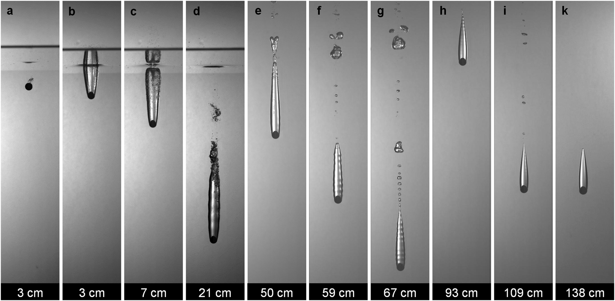 | ||
| Fig. 2 (a) Snapshot of an ethanol-washed 10 mm steel sphere (Θ ≈ 60°) crossing the air–water interface without cavity formation, after being released from 2.0 meters above the water surface. (b–k) Snapshots from composite Video 2 (ESI†) tracking the formation of the stable streamlined cavity attached to an unmodified 10 mm steel sphere (Θ ≈ 90°) following release from 2.0 meters above the water surface. (b–d) Impact and surface seal-off leading to cavity formation. (e–g) Bubble shedding with well pronounced acoustic ripples along the cavity. (h and i) Ripple pacification with reduced bubble shedding. (k) Stable-streamlined cavity configuration. The sphere depth below the water is indicated below each panel. Notice that the four panels of Video 2 (ESI†) were shot using an identical sphere dropped from the same height in consecutive runs. | ||
The snapshots given in Fig. 2b–d capture the initial cavity forming upon the unmodified sphere impact on the water surface. A seal-off cavity, which is typical for such impact velocities, is observed (Fig. 2c and d).5,10Fig. 2e–g track the gradual shedding of bubbles behind the cavity, which is assisted by the acoustic ripples propagating along the cavity surface.13 Further on the acoustic ripples gradually pacify with only smaller bubbles being shed, as seen in Fig. 2h and i. Finally, in Fig. 2k the ripples are fully pacified and the steady state sphere with attached cavity fall can be observed through the depths 115 to 150 mm below the water surface.
Most of the experiments in our study were conducted using unmodified spheres. However, as illustrated in Fig. 3 for the case of 10 mm steel spheres nearly identical attached cavities were produced for a variety of surface treatments, i.e. for plasma cleaned spheres (Θ < 30°, Fig. 3a), ethanol washed spheres (Θ ≈ 60°, Fig. 3b), unmodified spheres (Θ ≈ 90°, Fig. 3c), or hydrophobic spheres (Θ ≈ 120°, Fig. 3d), when they are released from the appropriate height above the water surface. The cavity-formation release height threshold was about 4 m for the plasma-cleaned sphere, 3.5 m for the ethanol cleaned sphere, and about 2 m for the unmodified sphere.
 | ||
| Fig. 3 Snapshots of the sphere attached-streamlined cavity for 10 mm steel spheres free-falling in room temperature water: (a) plasma cleaned sphere with water contact angle Θ < 30°, released from h0 = 4.2 meters above the water surface; (b) ethanol cleaned sphere Θ ≈ 60°, h0 = 3.2 m; (c) unmodified sphere Θ ≈ 90°, h0 = 2.0 m; and (d) ultra Glaco coated sphere Θ ≈ 120°, h0 = 0.5 m. | ||
For hydrophobic spheres the threshold height was about 0.5 meters, which is close to the release height used in our prior study with superhydrophobic spheres.14 A Leidenfrost or superhydrophobic sphere will form an initial cavity upon impact even when dropped from much lower heights. However, formation of an initial cavity is not a sufficient condition. As detailed in our prior studies13,14 even for non-wetted impact conditions one needs a larger threshold release height as the volume of the teardrop-cavity formed after the first cavity pinch-off should be larger enough to secure approximate neutral buoyancy of the sphere-in-cavity formation.
We note that for lower-density Teflon spheres (ρS = 2.2 g cm−3) used in a recent study of Di Mundo et al.9 the teardrop cavity is found to collapse following the first cavity pinch-off after the impact. The present study demonstrates a stable cavity formation for much larger sphere/fluid density ratios of ρS/ρ between 5.0 and 15. There may therefore be a critical minimum density ratio needed to achieve a stable cavity.
The comparison in Fig. 3 demonstrates that the sphere with attached cavity formation is nearly identical for the entire range of smooth sphere hydrophobicity investigated herein. The contact-lines all appear to be pinned at the same location, slightly above the equator (∼110° from the sphere bottom), irrespective of the value of Θ. This pinning may be assisted by the corner-flow separation upstream of the contact line.
The depth at which the stabilization of the sphere with cavity formation was observed increases with the sphere density and size, as well as with the sphere release height. For the 10 mm zirconia sphere it was about a 1.0 meter depth and for the 20 mm steel sphere about a 2.0 meter depth. Fig. S1 (ESI†) gives typical examples of the depth trajectory vs. time and descent velocity vs. time progression. For most of the spheres investigated here the sphere with attached cavity formation was still stable when reaching the bottom of the tank. However, we notice that if a deep enough tank is used the cavity will eventually collapse due to the buildup of hydrostatic pressure.13
A detailed analysis of the physics of the stable-streamlined cavity was done in our initial investigation for Leidenfrost-sphere impact on a fluorocarbon liquid.13 There it was suggested that a pre-condition for the pacification of the acoustic ripples along the side of the cavity is a lack of physical contact between the sphere and the cavity. However the present experiments demonstrate that in the case of water and a smooth sphere of a water contact angle between <30° and 120°, the ripples do eventually completely pacify even when a physical contact line between the cavity and the sphere is present.
By extending the phenomenon of a stable-streamlined cavity to wetting impacts we demonstrate that this is a far more general phenomenon than anticipated before. Simplified, if one releases a sphere from sufficient height above the water surface, at a certain depth a stable-streamlined cavity attached to the falling sphere can be produced. We note that although there have been numerous prior investigations1–8 of water-impact by steel spheres similar to the ones used in the present study, most of them were limited to the observation of the initial sphere impact until the cavity seal or shortly thereafter. Using deeper water tanks than in prior investigations allows us to track the sphere-with-cavity formation until the constant fall velocity steady-streamlined cavity state is observed.
3.2 Cavity shape, drag and fall velocity
Fig. 4 shows snapshots from Video 3 (ESI†), which compares the free fall of a sphere with an attached cavity formed by the impact of an unmodified DS = 15 mm steel sphere (Fig. 4a) and that formed by a DS = 15 mm superhydrophobic steel sphere (Fig. 4b). For reference we also show the sphere-in-cavity shape for a DS = 15 mm Leidenfrost steel sphere, TS = 400 °C in 95 °C water (Fig. 4c). As seen in Fig. 4 and Video 3 (ESI†) the sphere with attached cavity and sphere-in-cavity formations have a similar cavity shape and close free-fall velocities. This suggests that similar relations for the cavity volume, velocity and drag might hold for both formations. Therefore herein we follow the same characterization process for a sphere with an attached cavity as done earlier for the enclosed sphere-in-cavity formations.14 Table S1 (ESI†) summarises the physical characteristics of the spheres with attached cavities, such as the cavity length and diameter, terminal fall velocity, Reynolds number and drag coefficient. The dependences derived from these data are shown in Fig. 5–7 and discussed below.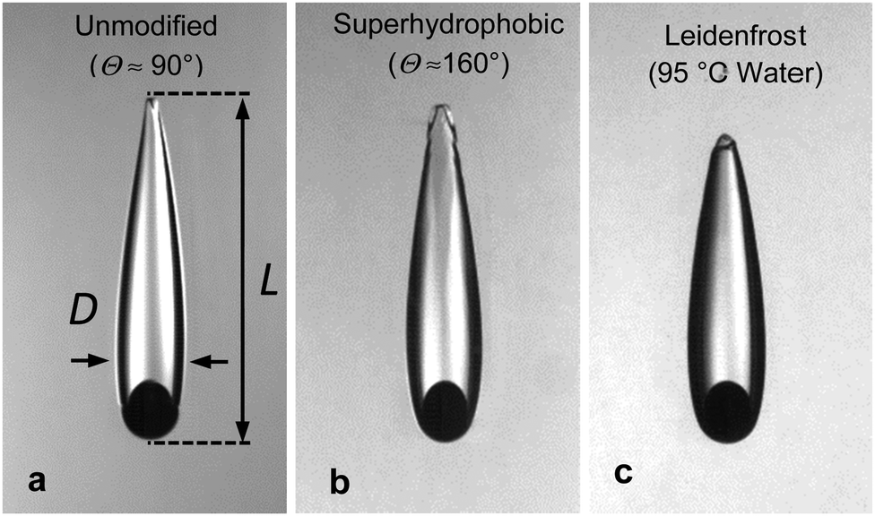 | ||
| Fig. 4 Snapshots from Video 3 (ESI†) comparing (a) a 15 mm unmodified steel sphere with cavity formation free-falling in room temperature water with (b) a 15 mm superhydrophobic steel sphere-in-cavity formation free-falling in room temperature water. (c) Sphere in cavity formation for a 15 mm Leidenfrost steel sphere, TS = 400 °C in 95 °C water.14 | ||
 | ||
| Fig. 5 (a) Dependence of the ratio of the total sphere-with-cavity over the sphere volume VSC/VS on the sphere to liquid density ratio ρS/ρ. The data shown are for 10 mm (green triangles), 15 mm (red squares) and 20 mm (blue circles) unmodified zirconia (ZO), steel (ST) or tungsten carbide (TC) spheres free falling in water. The dotted line corresponds to neutral buoyancy of the sphere-with-cavity formation. The insert images show silhouette snap-shots of 15 mm zirconia, 15 mm steel and 15 mm tungsten carbide sphere formation. (b) Cavity volume as a function of LD2 (cavity diameter D and length L) for the same sphere sizes as in (a). The same symbols are used as for (a). The dotted line is a best linear fit to the data, which gives the relation VSC = 0.47LD2. | ||
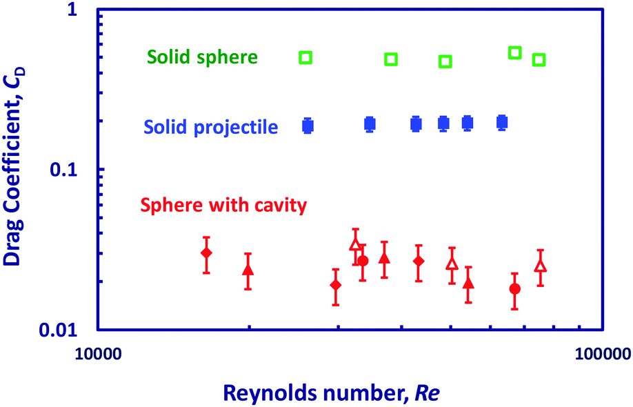 | ||
| Fig. 6 Variation of the drag coefficient CD with the Reynolds number Re for sphere-with-cavity for unmodified zirconia spheres of diameter DS = 10, 15 and 20 mm, L/R ≈ 4.0 (solid red diamonds), unmodified steel spheres of diameter DS = 10, 15 and 20 mm, L/R ≈ 4.7 (solid red triangles) and unmodified tungsten carbide spheres, DS = 10 and 15, L/R ≈ 6.3 (solid red circles). Data for solid spheres without a cavity (empty green squares) are taken from Jetly et al.32 Data for superhydrophobic steel sphere-in-cavity formation, DS = 15, 20 and 25 mm, L/R ≈ 4.5 (empty red triangles) and solid streamlined projectiles of similar shape, DP = 25 mm, LP/RP = 4.5 (solid blue squares), are taken from Vakarelski et al.14 See Fig. S2b (ESI†) for a picture of the streamlined solid projectile and Vakarelski et al.14 for further details on these measurements. | ||
 | ||
| Fig. 7 Variation of the sphere-with-cavity terminal velocity U with sphere diameter DS and sphere to liquid density ratio ρS/ρ − 1. The same sphere symbols are used as in Fig. 5a. The dotted line is a linear best fit to the data, giving a coefficient C = 4.7 in eqn (3). | ||
As in the case of a sphere-in-cavity formation, we observe that the spheres with attached cavities have self-similar shapes which depend only on the ratio between the sphere and liquid densities. The aspect ratio of the sphere-with-cavity length to the maximum diameter was found to be L/D ∼ 4.0 for the zirconia spheres; L/D ∼ 4.8 for the steel spheres, and L/D ∼ 6.3 for the tungsten carbide spheres (see Fig. 4a for the L and D definitions). These ratios are slightly higher than for the sphere-in-cavity formations, reflecting the fact that the cavity is now attached above the sphere equator, giving a slimmer streamlined profile (Fig. 4).
The total volume of the cavity with sphere formation, VSC, (including the sphere and the cavity volume) was estimated from the video snapshots using a profile tracking MATLAB image processing code. In our prior work we have shown that the formation shape can be also fitted using a three-piece algebraic curve that comprises a spherical front section, an elliptical mid-section and a parabolic tail.14
As in the sphere-in-cavity case we find that the ratio of the volume of the sphere with attached cavity formation to the volume of the sphere VSC/VS was always only slightly less than the ratio of the sphere density to the fluid density, ρS/ρ. This is demonstrated by the Fig. 5a data showing the VSC/VSvs. ρS/ρ dependence. This means that the sphere with attached cavity formation is nearly neutrally buoyant. Furthermore, the volume of the sphere–cavity formation was found to be empirically related to the L and D dimensions as VSC ≈ 0.47LD2 for all combinations of sphere density and size studied, as shown in Fig. 5b.
The drag coefficient of the sphere-with-cavity, CD, was estimated from the formation terminal velocity U and the sphere with cavity formation volume VSC, using the following relation from the balance of the buoyancy and drag force:
 | (1) |
Fig. 6 shows the dependence of the sphere-with-cavity drag coefficient, CD, on the Reynolds number, Re = ρDU/μ, using data for zirconia, steel and tungsten carbide spheres. For comparison we also show data for the drag of the enclosed sphere-in-cavity formation using superhydrophobic steel spheres, and the drag of similar streamlined-shape solid projectiles measured in our recent study.14 The average value of the drag coefficient, CD = 0.025 ± 0.010, of the sphere with attached cavity formation is similar to the value found for the sphere-in-cavity formation (e.g. superhydrophobic or Leidenfrost spheres in a cavity). This is close to an order of magnitude lower than the drag on the similar shape streamlined solid projectile, CD ≈ 0.2, or sphere without a cavity, CD ≈ 0.45.25 The drag measured on Leidenfrost spheres (without cavities) in our prior studies can also be comparatively low, reaching a CD = 0.04 ± 0.01 value, but is manifested as an early drag crisis phenomenon, triggered above a certain Reynolds number.26–29 In contrast the drag on the sphere with a cavity seems to be equally pronounced in the entire range of Reynolds numbers investigated.
The low drag on the sphere-with-cavity is due to the streamlined shape of the formation and importantly to the exchange of the no-slip boundary condition on the solid-water interface with the free-slip or stress-free boundary condition along the cavity gas–liquid interface. Here we show a similar drag value for the sphere-in-cavity formation in which case the sphere is completely isolated from the liquid and for the sphere-with-cavity formation in which case there is direct contact between the front part of the sphere and the liquid. However this is perhaps not surprising, having in mind that the air layer between the front of the sphere and the cavity before the cavity separation from the sphere is very thin and provides only partial effective slip.30–32 The direct contact between the sphere and the liquid could explain the residual drag on the formation.
An important property of the sphere-in-cavity formation, found in our prior study, was that although the formation drag is near-zero, the cavity fall-velocity has a discrete value.14 The velocity value is determined by matching the hydrostatic pressure gradient in the pool with the dynamic pressure from the Bernoulli equation along the free surface, while the pressure inside the gas-cavity is constant:
 | (2) |
| U2 ≈ C(gDS)[(ρS/ρ) − 1] | (3) |
The close values of the drag coefficient and fall velocity between the sphere-in-cavity formation and the sphere with attached cavity formation shown here demonstrate that both are near-zero drag formations for which the fall velocity complies with the potential flow theory and Bernoulli equation along the cavity interface. We also note that the physical model used to describe the fall velocity of the streamlined cavity is reminiscent of the Davies–Taylor study of the rise velocity of a large spherical cap gas bubble in liquid.33
3.3 Effect of surfactant additives
The near-zero drag on the sphere with a streamlined cavity is a result of the streamlined shape and the free-slip boundary condition along the cavity interface, as confirmed by comparing the drag on sphere-with-cavity and sphere-in-cavity formations with the drag on similar shape solid projectiles (Fig. 6). It is well known that surface active additives can effectively immobilize the air–liquid interface. For small bubbles, even trace amounts of surfactant can lead to interface immobilization. However for the larger gas cavities and high interface shear rates in our experiments the interface sensitivity to surfactant additives will depend on the surfactant type and concentration.In our choice of test surfactants we follow foam rheology investigations24,34–37 that have clarified two types of surfactant additives with respect to their effect on the foam-bubble mobility. The first are typically synthetic surfactants (for example SDS) which show low surface modulus and fast relaxation of the surface tension following surface dilation. The second type, exemplified by the sodium and potassium salts of fatty acids (also known as soaps), have a high surface modulus and slow surface tension relaxation. Foam shearing experiments indicate that for the low-surface-modulus surfactants the bubble interface behaves as mobile, and in contrast for the high surface modulus surfactants the foam bubble interface behaves as immobile.34–36
As examples of low modulus surfactants here we use 10 mM SDS water solution and a commercial shampoo (Johnson's® Baby Shampoo) water solution which is soap free. As examples of high modulus surfactants we use a mixture of SLES + CAPB surfactants + myristic acid (MAc) and also a high concentration solution of a regular toilet soap (Coast® soap) that contains various sodium fatty acids. The advantage of the SLES + CAPB + MAc mixture is that following the preparation protocol the solution stays clear and transparent, whereas the toilet soap solution fast becomes turbid.24 Details of all surfactant solutions’ composition, concentration and preparation are given in the Experimental section and summarized in Table S2 (ESI†).
Video 4 (ESI†) compares the free-fall of a 10 mm unmodified steel sphere with an attached cavity in pure water, SDS solution, shampoo solution, SLES + CAPB + MAc solution and soap solution. Fig. 8 shows snapshots for the pure water and various surfactant solutions taken from this video. As can be seen in the video and the snapshots for the cases of the SDS solution (Fig. 8b) and shampoo solution (Fig. 8c) we observed stable attached cavities with nearly identical shape and fall velocity to the case of cavities formed in pure water (Fig. 8a). This result indicates that the low-surface-modulus surfactants are not affecting the mobility of the cavity interface and the cavity behaves as having a free-slip interface. It also shows that the strength of the air–liquid surface tension does not seem to affect substantially the cavity formation. This is in agreement with previous results for sphere-in-cavity formation using low surface tension PP1 liquid.13
 | ||
| Fig. 8 Snapshots from Video 4 (ESI†) comparing 10 mm unmodified steel spheres with cavity formation free-falling in pure water and different surfactant solutions: (a) pure water; (b) SDS solution; (c) shampoo solution; (d) SLES + CAPB + MAc solution; and (e) soap solution. The estimated drag coefficients for each case were: (a) CD ≈ 0.03; (b) CD ≈ 0.03; (c) CD ≈ 0.03; (d) CD ≈ 0.30; and (e) CD ≈ 0.10. | ||
The observation that even very high concentrations of surfactant above the CMC that readily lower the surface tension of water do not affect the mobility and the shape of the cavity formation might seem surprising. However this result is in good agreement with the foam rheology investigations that indicate free-slip on bubbles for foams formed using low-surface-modulus surfactants.34–36 At the same time it is in sharp contrast with the behaviour of micron sizes bubbles in water, in which case even trace amounts of contamination are found to immobilise the interface as evaluated in rising bubble terminal velocity experiments38–41 and in bubble interaction in atomic force microscopy (AFM) experiments.42,43 This behaviour clearly demonstrates that the mobility of the air–water interface strongly depends on the flow regime and related tangential stress applied on the bubbles or cavity interface. For small bubbles and low shear stress close to the Stokes regime even a trace amount of surfactant that does not change the surface tension will fully immobilize the interface and the bubbles behave like rigid particles.38–44 For larger deformable bubbles their rise velocity is in agreement with the mobile-surface rise velocity predicted by the Moor theory45 of stress-free interface bubbles, unless a higher concentration of surfactant is added.46–48 Finally for the larger foam bubbles and higher shear rates, as well as in our falling cavity experiments, even for concentrations of synthetic surfactants above the CMC the interface remains free-slip.
In contrast to the low modulus surfactants, in the case of the SLES + CAPB + MAc solution it was not possible to form a stable cavity. Shortly after the sphere impacts the water surface the cavity was either completely detached from the sphere, or as in the example given in Video 4 (ESI†) (Fig. 8d) was constantly shedding. In the case of the soap solution (Fig. 8e), we observed an intermediate case of a “cut-tail” cavity formation. The fall velocity of the sphere with a cut-tail cavity is close to that of the sphere with streamlined cavity formation as seen in Video 4 (ESI†). However for the case of the cut-tail the cavity volume VSC is much smaller, i.e. the formation is less buoyant and therefor the drag is higher, estimated to be CD ≈ 0.1, for the example given in Fig. 8e, and even higher, CD ≈ 0.3, for the example given in Fig. 8d. On the other hand, when the cavity is completely removed the drag will increase to the limiting case of a sphere without a cavity CD ≈ 0.45. Thus we show that viscous stress on the cavity interface eventually leads to partial, in the case of the soap solution, or complete, as in the case of the SLES + CAPB + MAc solution, cavity destruction.
The surfactant-mixture and soap-solution results are in agreement with the foam shearing experiments, confirming the trend that high elastic modulus surfactants are effective in immobilising the interface. We note however that the SLES + CAPB + MAc concentration needed in our experiment to destabilize the cavity was about 8 times higher (∼4 wt%) than the concentration used in the foam rheology experiments.34–36 Using a lower ∼0.5 wt% concentration, which was shown to immobilise bubbles in foam shear experiments, we were still able to produce stable cavity formations. This reflects the fact that cavity formation is a more dynamic process than foam shearing, which follows the general trend of higher shear stress resulting in higher interface mobility. A related experimental detail was that when a sphere was impacting a foam covered water interface, instead of a foam-free interface as in the rest of the experiments, a stable cavity formation was occasionally observed even in the case of the higher concentration SLES + CAPB + MAc solution. The effect of foam on top of water on the initial cavity formation has been recently investigated,11 however the exact mechanism of cavity stabilisation in our experiments will require further investigation.
We finally note that the surfactant mixture solution experiments showed that the immobilisation of the interface did not result in a stable-streamlined cavity of higher drag close to that of the similar shape solid projectile (CD ∼ 0.2) as one might assume. Instead the cavity was partially formed as in the cut-tail formation (Fig. 8e) or completely destroyed (Fig. 8d). This indicates that the teardrop streamlined cavity is a stable formation only as long as its interface is stress-free. One way to estimate if the cavity mobility will be affected by the presence of a surfactant additive is to compare the magnitude of the surface dilation modulus, Es.34–36 For the SDS solution Es ≈ 3.0 mN m−1 (SDS solution surface tension σ ≈ 38.5 mN m−1), while for the SLES + CAPB + MAc and soap solutions it is much larger, Es = 300 to 400 mN m−1 (σ ≈ 27.0 mN m−1).34 A comprehensive model that relates the shear viscous stress at which the interface become mobile with the dilation properties of the interface under various surfactant additive conditions will be addressed in future investigations. However, we point out that our experiment is a much simpler system to test such models compared to foam rheology experiments where the shear force is averaged over many bubbles.34–36
4 Conclusions
A sphere inside a stable-streamlined gas cavity free-falling in liquid is a recently discovered phenomenon that is a practical realisation of an object moving in a fluid approaching the near zero-drag predicted by the well-known d’Alembert paradox.14 In our initial study of this phenomenon a pre-condition for the formation of the stable cavity was non-wetting sphere impact. Here we show that similar stable-streamlined cavity formation can be observed following the water impact of a smooth sphere with a wide range of water contact angles, from fully wetted hydrophilic spheres to hydrophobic spheres. The only requirement is that the sphere is released from sufficient height above the water surface to initiate cavity formation, and that the liquid tank is deep enough to observe the stabilised cavity. The difference between the non-wetting sphere formation and wetted sphere formation is that in the case of wetted spheres the streamlined cavity is attached just above the sphere equator instead of entirely wrapping the sphere. Nevertheless, the sphere with an attached cavity shows the same low drag and same dependence of the free-fall velocity on the sphere size and density as the sphere in the enclosed cavity investigated before. Finally, we study the effect of added surfactants to the water on the streamlined cavities. It was found that even high concentration low-surface-modulus synthetic surfactant mixtures did not affect the cavity shape or fall velocity, indicating that the interface remains free-slip. When high concentration high-surface-modulus surfactant mixtures, e.g. soap solutions, were used the cavity was partially or completely destroyed, indicating interface immobilization. These results are in good agreement with foam rheology experiments. However, a higher surfactant concentration was needed to immobilize the interface than in the case of foam shearing experiments, confirming the trend of higher liquid–air interface tangential mobility at higher interface shear rates.Conflicts of interest
The authors declare no conflict of interest.Acknowledgements
We acknowledge Dr Krastanka Marinova for advice on the surfactant solution formulation. This work was supported by King Abdullah University of Science and Technology (KAUST).References
- T. T. Truscott, B. P. Epps and J. Belden, Water entry of projectiles, Annu. Rev. Fluid Mech., 2014, 46, 355–378 CrossRef.
- D. Gilbarg and R. A. Anderson, Influence of atmospheric pressure on the phenomena accompanying the entry of spheres into water, J. Appl. Phys., 1948, 19, 127–139 CrossRef.
- V. Duclaux, F. Caillé, C. Duez, C. Ybert, L. Bocquet and C. Clanet, Dynamics of transient cavities, J. Fluid Mech., 2007, 591, 1–19 CrossRef CAS.
- C. Duez, C. Ybert, C. Clanet and L. Bocquet, Making a splash with water repellency, Nat. Phys., 2007, 3, 180–183 Search PubMed.
- J. M. Aristoff and J. W. M. Bush, Water entry of small hydrophobic spheres, J. Fluid Mech., 2009, 619, 45–78 Search PubMed.
- J. M. Aristoff, T. T. Truscott, A. H. Techet and J. W. M. Bush, The water entry of decelerating spheres, Phys. Fluids, 2010, 22, 032102 Search PubMed.
- M.-H. Zhao, X.-P. Chen and Q. Wang, Wetting failure of hydrophilic surfaces promoted by surface roughness, Sci. Rep., 2014, 4, 5376 Search PubMed.
- M. M. Mansoor, J. O. Marston, I. U. Vakarelski and S. T. Thoroddsen, Water entry without surface seal: extended cavity formation, J. Fluid Mech., 2014, 743, 295–326 Search PubMed.
- R. Di Mundo, F. Bottiglione, G. Pascazio and G. Carbone, Water entry and fall of hydrophobic and superhydrophobic Teflon spheres, J. Phys.: Condens. Matter, 2018, 30, 445001 CrossRef CAS.
- N. B. Speirs, M. M. Mansoor, J. Belden and T. T. Truscott, Water entry of spheres with various contact angles, J. Fluid Mech., 2019, 862, R3 CAS.
- N. B. Speirs, M. M. Mansoor, R. C. Hurd, S. I. Sharker, W. G. Robinson, B. J. Williams and T. T. Truscott, Entry of a sphere in a water-surfactant mixture and the effect of a bubble layer, Phys. Rev. Fluids, 2018, 3, 104004 CrossRef.
- J. O. Marston, I. U. Vakarelski and S. T. Thoroddsen, Cavity formation by the impact of Leidenfrost spheres, J. Fluid Mech., 2012, 699, 465–488 CrossRef CAS.
- M. M. Mansoor, I. U. Vakarelski, J. O. Marston, T. T. Truscott and S. T. Thoroddsen, Stable-streamlined and helical cavities following the impact of Leidenfrost spheres, J. Fluid Mech., 2017, 823, 716–754 CrossRef.
- I. U. Vakarelski, E. Klaseboer, A. Jetly, M. M. Mansoor, A. A. Aguirre-Pablo, D. Y. C. Chan and S. T. Thoroddsen, Self-determined shapes and velocities of giant near-zero drag gas cavities, Sci. Adv., 2017, 3, e1701558 CrossRef.
- S. L. Ceccio, Friction drag reduction of external flows with bubble and gas injection, Annu. Rev. Fluid Mech., 2010, 42, 183–203 CrossRef.
- G. McHale, M. I. Newton and N. J. Shirtcliffe, Immersed superhydrophobic surfaces: Gas exchange, slip and drag reduction properties, Soft Matter, 2010, 6, 714–719 RSC.
- J. P. Rothstein, Slip on superhydrophobic surfaces, Annu. Rev. Fluid Mech., 2010, 42, 89–109 CrossRef.
- H. Dong, M. Cheng, Y. Zhang, H. Wei and F. Shi, Extraordinary drag-reducing effect of a superhydrophobic coating on a macroscopic model ship at high speed, J. Mater. Chem. A, 2013, 1, 5886–5891 RSC.
- I. U. Vakarelski, D. Y. C. Chan and S. T. Thoroddsen, Drag moderation by the melting of an ice surface in contact with water, Phys. Rev. Lett., 2015, 115, 044501 CrossRef.
- D. Saranadhi, D. Chen, J. A. Kleingartner, S. Srinivasan, R. E. Cohen and G. H. McKinley, Sustained drag reduction in a turbulent flow using a low-temperature Leidenfrost surface, Sci. Adv., 2016, 2, e1600686 CrossRef PubMed.
- J. G. Leidenfrost, Int. J. Heat Mass Transfer, 1966, 9, 1153 CrossRef CAS.
- I. U. Vakarelski, N. A. Patankar, J. O. Marston, D. Y. C. Chan and S. T. Thoroddsen, Stabilization of Leidenfrost vapour layer by textured superhydrophobic surfaces, Nature, 2012, 489, 274–277 CrossRef CAS.
- D. Quéré, Leidenfrost Dynamics, Annu. Rev. Fluid Mech., 2013, 45, 197–215 CrossRef.
- K. Golemanov, N. D. Denkov, S. Tcholakova, M. Vethamuthu and A. Lips, Surfactant mixtures for control of bubble surface mobility in foam studies, Langmuir, 2008, 24, 9956–9961 CrossRef CAS.
- E. Achenbach, Experiments on the flow past spheres at high Reynolds umbers, J. Fluid Mech., 1972, 54, 565–575 CrossRef CAS.
- I. U. Vakarelski, J. O. Marston, D. Y. C. Chan and S. T. Thoroddsen, Drag reduction by Leidenfrost vapor layers, Phys. Rev. Lett., 2011, 106, 214501 CrossRef.
- I. U. Vakarelski, D. Y. C. Chan and S. T. Thoroddsen, Leidenfrost vapour layer moderation of the drag crisis and trajectories of superhydrophobic and hydrophilic spheres falling in water, Soft Matter, 2014, 10, 5662–5668 RSC.
- I. U. Vakarelski, J. D. Berry, D. Y. C. Chan and S. T. Thoroddsen, Leidenfrost vapor layers reduce drag without the crisis in high viscosity liquids, Phys. Rev. Lett., 2016, 117, 114503 CrossRef.
- A. Jetly, I. U. Vakarelski, Z. Yang and S. T. Thoroddsen, Giant drag reduction on Leidenfrost spheres evaluated from extended free-fall trajectories, Exp. Therm. Fluid Sci., 2019, 102, 181–188 CrossRef CAS.
- G. McHale, N. J. Shirtcliffe, C. R. Evans and M. I. Newton, Terminal velocity and drag reduction measurements on superhydrophobic spheres, Appl. Phys. Lett., 2009, 94, 064104 CrossRef.
- A. Busse, N. D. Sandham, G. McHale and M. I. Newton, Change in drag, apparent slip and optimum air layer thickness for laminar flow over an idealised superhydrophobic surface, J. Fluid Mech., 2013, 727, 488–508 CrossRef.
- A. Jetly, I. U. Vakarelski and S. T. Thoroddsen, Drag crisis moderation by thin air layers sustained on superhydrophobic spheres falling in water, Soft Matter, 2018, 14, 1608–1613 RSC.
- R. M. Davies and G. Taylor, The mechanics of large bubbles rising through extended liquids and through liquids in tubes, Proc. R. Soc. A, 1950, 200, 375–390 CrossRef.
- N. D. Denkov, V. Subramanian, D. Gurovich and A. Lips, Wall slip and viscous dissipation in sheared foams: Effect of surface mobility, Colloids Surf., A, 2005, 262, 129–145 CrossRef.
- N. D. Denkov, S. Tcholakova, K. Golemanov, K. P. Ananthapadmanabhan and A. Lips, Viscous friction in foams and concentrated emulsions under steady shear, Phys. Rev. Lett., 2008, 100, 138301 CrossRef CAS.
- N. D. Denkov, S. Tcholakova, K. Golemanov, K. P. Ananthpadmanabhan and A. Lips, The role of surfactant type and bubble surface mobility in foam rheology, Soft Matter, 2009, 5, 3389–3408 RSC.
- K. G. Marinova, K. T. Naydenova, E. S. Basheva, F. Bauer, J. Tropsch and J. Franke, New surfactant mixtures for fine foams with slowed drainage, Colloids Surf., A, 2017, 523, 54–61 CrossRef CAS.
- G. H. Kelsall, S. Tang, A. L. Smith and S. Yurdakul, Measurement of rise and electrophoretic velocities of gas bubbles, J. Chem. Soc., Faraday Trans., 1996, 92, 3879–3885 RSC.
- L. Parkinson, R. Sedev, D. Fornasiero and J. Ralston, The terminal rise velocity of 10–100 μm diameter bubbles in water, J. Colloid Interface Sci., 2008, 322, 168–172 CrossRef CAS.
- I. U. Vakarelski, R. Manica, E. Q. Li, E. S. Basheva, D. Y. C. Chan and S. T. Thoroddsen, Coalescence dynamics of mobile and immobile fluid interfaces, Langmuir, 2018, 34, 2096–2108 CrossRef CAS.
- P. Pawliszak, V. Ulaganathan, B. H. Bradshaw-Hajek, R. Manica, D. A. Beattie and M. Krasowska, Mobile or immobile? Rise velocity of air bubbles in high purity water, J. Phys. Chem. C, 2019, 123, 15131–15138 CrossRef CAS.
- O. Manor, I. U. Vakarelski, X. Tang, S. J. O’Shea, G. W. Stevens, F. Grieser, R. R. Dagastine and D. Y. C. Chan, Hydrodynamic boundary conditions and dynamic forces between bubbles and surfaces, Phys. Rev. Lett., 2008, 101, 024501 CrossRef.
- I. U. Vakarelski, R. Manica, X. S. Tang, S. J. O’Shea, G. W. Stevens, F. Grieser, R. R. Dagastine and D. Y. C. Chan, Dynamic interactions between microbubbles in water, Proc. Natl. Acad. Sci. U. S. A., 2010, 107, 11177–11182 CrossRef CAS.
- B. Liu, R. Manica, Q. Liu, E. Klaseboer, Z. Xu and G. Xie, Coalescence of bubbles with mobile interfaces in water, Phys. Rev. Lett., 2019, 122, 194501 CrossRef CAS.
- D. W. Moore, The velocity of rise of distorted gas bubbles in a liquid of small viscosity, J. Fluid Mech., 1965, 23, 749–766 CrossRef.
- S. Okazaki, The velocity of ascending air bubbles in aqueous solutions of a surface active substance and the life of the bubble on the same solution, Bull. Chem. Soc. Jpn., 1964, 37, 144–150 CrossRef CAS.
- K. Malysa, M. Krasowska and M. Krzan, Influence of surface active substances on bubble motion and collision with various interfaces, Adv. Colloid Interface Sci., 2005, 114–115, 205–225 CrossRef CAS.
- R. Manica, E. Klaseboer and D. Y. C. Chan, The hydrodynamics of bubble rise and impact with solid surfaces, Adv. Colloid Interface Sci., 2016, 235, 214–232 CrossRef CAS.
Footnote |
| † Electronic supplementary information (ESI) available: A pdf file containing: Fig. S1. Depth vs. time and velocity vs. time data; Fig. S2. Picture of a sphere with a cavity and a streamlined projectile; Table S1; Table S2. Video 1. Parallel free-fall of 10 mm zirconia (left), 10 mm steel (middle) and 10 mm tungsten carbide (right) spheres with attached cavities. The frame rate is 2000 fps and playback speed 30 fps. Video 2. Composite video tracking the cavity formation for a 10 mm steel sphere inside the water tank. Video 3. Parallel free-fall of a 15 mm unmodified sphere with attached cavity formation (left) and 15 mm superhydrophobic steel sphere-in-cavity formation (right). The frame rate is 2000 fps and playback speed 30 fps. Video 4. Parallel free-fall of a 10 mm unmodified steel sphere in water solutions (from left): DI water; SDS solution; shampoo solution; SLES + CAPB + MAc solution; and soap solution. The frame rate is 2000 fps and playback speed 30 fps. See DOI: 10.1039/c9sm01025d |
| This journal is © The Royal Society of Chemistry 2019 |