 Open Access Article
Stokesian dynamics of sedimenting elastic rings†
Magdalena
Gruziel-Słomka
a,
Paweł
Kondratiuk
b,
Piotr
Szymczak
 b and
Maria L.
Ekiel-Jeżewska
 *a
*a
aInstitute of Fundamental Technological Research, Polish Academy of Sciences, Paw-ińskiego 5B, 02-106, Warsaw, Poland. E-mail: mekiel@ippt.pan.pl
bInstitute of Theoretical Physics, Faculty of Physics, University of Warsaw, 02-093, Pasteura 5, Warsaw, Poland
First published on 23rd August 2019
Abstract
We consider elastic microfilaments which form closed loops. We investigate how the loops change shape and orientation while settling under gravity in a viscous fluid. Loops are circular at the equilibrium. Their dynamics are investigated numerically based on the Stokes equations for the fluid motion and the bead–spring model of the microfilament. The Rotne–Prager approximation for the bead mobility is used. We demonstrate that the relevant dimensionless parameter is the ratio of the bending resistance of the filament to the gravitation force corrected for buoyancy. The inverse of this ratio, called the elasto-gravitation number ![[scr B, script letter B]](https://www.rsc.org/images/entities/char_e13f.gif) , is widely used in the literature for sedimenting elastic linear filaments. We assume that
, is widely used in the literature for sedimenting elastic linear filaments. We assume that ![[scr B, script letter B]](https://www.rsc.org/images/entities/char_e13f.gif) is of the order of 104–106, which corresponds to easily deformable loops. We find out that initially tilted circles evolve towards different sedimentation modes, depending on
is of the order of 104–106, which corresponds to easily deformable loops. We find out that initially tilted circles evolve towards different sedimentation modes, depending on ![[scr B, script letter B]](https://www.rsc.org/images/entities/char_e13f.gif) . Very stiff or stiff rings attain almost planar, oval shapes, which are vertical or tilted, respectively. More flexible loops deform significantly and converge towards one of several characteristic periodic motions. These sedimentation modes are also detected when starting from various shapes, and for different loop lengths. In general, multi-stability is observed: an elastic ring converges to one of several sedimentation modes, depending on the initial conditions. This effect is pronounced for very elastic loops. The surprising diversity of long-lasting periodic motions and shapes of elastic rings found in this work gives a new perspective for the dynamics of more complex deformable objects at micrometer and nanometer scales, sedimenting under gravity or rotating in a centrifuge, such as red blood cells, ring polymers or circular DNA.
. Very stiff or stiff rings attain almost planar, oval shapes, which are vertical or tilted, respectively. More flexible loops deform significantly and converge towards one of several characteristic periodic motions. These sedimentation modes are also detected when starting from various shapes, and for different loop lengths. In general, multi-stability is observed: an elastic ring converges to one of several sedimentation modes, depending on the initial conditions. This effect is pronounced for very elastic loops. The surprising diversity of long-lasting periodic motions and shapes of elastic rings found in this work gives a new perspective for the dynamics of more complex deformable objects at micrometer and nanometer scales, sedimenting under gravity or rotating in a centrifuge, such as red blood cells, ring polymers or circular DNA.
1 Introduction
At micrometer and nanometer scales, there appear a variety of elastic, deformable objects moving in a fluid environment, such as proteins, DNA, algae, bacteria, vesicles or red blood cells. Therefore, there is growing interest in theoretical and numerical modeling of the dynamics of such systems, sedimenting under gravitational or centrifugal forces, entrained by external fluid flows, or swimming, with or without a significant influence of the Brownian displacements.Motion of elongated elastic linear filaments has already been extensively studied.1–10 However, it is also of great interest to investigate the dynamics and characteristic shapes attained by elastic circular filaments. Such loops are often formed by proteins, DNA,11–19 or ring polymers,20–24 which are usually much longer than they are thick. The dynamics of ring-like filaments of a relatively short length is also of great interest as a simple model of more complex objects, such as e.g. red blood cells, vesicles or capsules.25–31 An interesting problem which attracts a lot of attention is how the topology of such loops – the type of knots tied on the elastic filaments – affects the dynamics and other mechanical properties.32–44 Such knotted structures are often found in nature and biotechnology, in connection with specific biological functions.45–48 The dynamics of unknotted loops is also interesting as a reference. Surprisingly, until now the dynamics of a single elastic ring sedimenting under gravity in a viscous fluid in the Stokesian regime has not been studied. The aim of this work is to contribute towards filling this gap.
The plan of the paper is the following. Section 2 is devoted to a brief description of the bead–spring model of the elastic ring and its Stokesian dynamics. Normalization and dimensionless parameters are introduced. The most important quantity is the ratio of bending to hydrodynamic forces acting on the ring, called the bending stiffness.
This description is followed in Section 3 by the results of simulations of rings made of sixty beads, starting from a tilted circle. The tilt is introduced as the simplest perturbation of the circular shape in horizontal orientation (which does not change while settling). This subtle modification of the initial condition leads to fascinating results: tilted rings yield various stationary configurations or periodic motions dependent only on the bending stiffness of the ring (and not on the initial tilt angle).
Further on, in Section 4, the generality of the previous observations is demonstrated. This is done through the analysis of simulations of sedimenting elastic rings with various numbers of beads. Also, for rings made of sixty beads, a series of simulations is performed which start from various initial configurations and, as previously, for different values of the bending stiffness. The latter simulations lead to observation of multi-stability of the studied systems: at certain values of the bending stiffness, several attracting sedimentation modes are available: stable configurations or periodic oscillations. Section 5 contains the final conclusions.
2 Model
2.1 Mechanical model of loops
A model ring consists of N identical beads of diameters d whose virtual bonds (a link between two consecutive overlapping beads) and bond angles (an angle between two consecutive bonds) are constrained by Hookean springs. The stretching potential energy for a single bond of length li is given by Ei,b = B*(li − l0)2/2, with a large spring constant B* = 50F0/d, where F0 is a gravitational force, corrected for buoyancy, acting on each of the beads, and l0 = 0.6d – the equilibrium bond length. The value of B* was selected in such a way that it corresponds to a practically non-extensible filament. In our model the beads are free to rotate. However, the equilibrium distance l0 between the bead centers was chosen much smaller than their diameter in order to hinder their rotation. The influence of free rotation on the dynamics of close non-overlapping beads with lubrication interactions was discussed in ref. 49.The bending potential energy for a single angle ϕi between consecutive bonds is given by Ei,a = A*(ϕi − ϕ0)2/(2l0), where A* and ϕ0 = π are the bending stiffness and the equilibrium bond angle, respectively.
To prevent complete overlapping of beads and thus chain self-crossing, a truncated Lennard-Jones potential energy Ei,rep = ε*((σ*/rij*)12 − (σ*/rij*)6), rij* < 21/6σ*, is used to represent steric constraints between non-consecutive beads i, j, with σ* = 0.5d and ε* = 0.25dF0. These three potential energies lead to stretching, bending and repulsive forces acting on each bead, i.e.Fi,b, Fi,a, and Fi,rep, respectively, for the ith bead. Additionally, gravity is applied as a constant external force along the z-axis, i.e.Fi,g = (0, 0, F0), for a single, ith bead.
Thus, the total external force acting on a single bead becomes:
| Fi = Fi,b + Fi,a + Fi,rep + Fi,g | (1) |
2.2 Stokesian dynamics
The total force (eqn (1)) is then included in the equations of motion for the i-th bead within a Stokesian dynamics scheme as in ref. 50–60. | (2) |
The mobility matrix is represented by the Rotne–Prager–Yamakawa approximation,61,62![[thin space (1/6-em)]](https://www.rsc.org/images/entities/char_2009.gif) ‡ allowing for overlapping beads i ≠ j:
‡ allowing for overlapping beads i ≠ j:
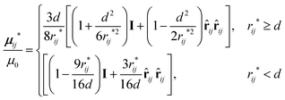 | (3) |
2.3 Non-dimensional variables
As a reference velocity, v0, we take the velocity of a spherical bead of diameter d, moving under gravity in a fluid of viscosity η: | (4) |
The lengths and velocities are scaled as r = r*/d, and v = v*/v0, respectively. The time is scaled by the time τd = d/v0 needed for a bead of velocity v0 to travel the length of its diameter, t = t*/τd. The force constants for stretching, B*, and repulsion, ε*, in dimensionless form become B = B*d/F0 and ε = ε*/(dF0). The most important dimensionless parameter governing the dynamics of the system is the ratio  of bending to hydrodynamic forces acting on the chain. Its inverse, sometimes called the elasto-gravitational number,1–5,7,8 is widely used in the literature as the standard parameter in dynamics of sedimenting elastic linear filaments.1–9 For small deformations, the dynamics of an elastic thin filament depends on its bending stiffness and length only through the elasto-gravitation number.64
In this paper, we focus on very elastic loops, in the range A ≪ 1, with the most interesting dynamics observed for A of the order of 10−4 or even smaller. Therefore, owing to the very small values of A involved, we find it convenient to introduce an additional scaling factor of 6 × 10⁴ so that finally the dimensionless bending stiffness is
 | (5) |
In the literature, sedimentation of elastic fibers with open ends has been studied for a wide range of the elasto-gravitational number. Simulations and experiments were performed for A ≪ 1,1–5,7,8,65 with the interesting sedimentation modes appearing for A of the order of 10−2–10−4. Typically, for the gravitational settling of actin, diatoms and microfibers, A can be as small as around 10−2, as discussed in ref. 7 and 65. However, in fast ultracentrifugation, the corresponding values of A will be several orders of magnitude smaller.
3 Sedimentation modes
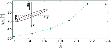
It is natural to start our considerations with the initial conditions of the simplest form, corresponding to a circular ring. When the settling is initiated from the horizontal orientation, the loop always remains a horizontal circle, regardless of the value of the bending stiffness parameter Ã. Therefore, we initiate the simulations with a circular ring slightly tilted with respect to the horizontal plane, as sketched in the inset of Fig. 1. The tilt angle, denoted as β, is defined as the angle between the plane of the circular loop and the horizontal plane. It is thus equal to e.g. 0° or 90° for the horizontal and vertical orientations, respectively. The initial tilt angle is varied from 0° up to about β0 = 16°.In this section, the number of beads in the chain is set to N = 60 and β0 = 16°. The bending stiffness is varied in a wide range of values, 0.2 ≲ Ã ≲ 2.8.
The dynamics reveals a diversity of fascinating stationary configurations or periodic orbits, which are superposed with translations. Such motions will be further called sedimentation modes. They are reached after a certain relaxation time and continue until the end of the simulation. Their basic features will be described in the following subsections.
3.1 Relatively stiff chains, Ã ≳ 1
As it has turned out, the most stiff rings (à ≥ A1 ≈ 2.1) have an increasing tilt angle in the course of evolution up to vertical orientation, whereas slightly less stiff rings (à < A1) have an increasing tilt angle up to a certain final βfin < 90° at which they remain till the end of the simulation. In the latter case, the vertical settling of the loop is accompanied by a steady drift in the horizontal direction. This effect is analogous to the horizontal drift of two identical spherical particles with the line of the centers inclined with respect to gravity or the horizontal drift of a sedimenting inclined rod.66 The final tilt angle βfin is plotted in Fig. 1 as a function of bending stiffness Ã. Importantly, the value of the final tilt angle is the same for a given Ã, regardless of the initial β0, although the stationary state will be reached earlier for larger initial tilt angles. See also Movie 1 provided in the ESI,† showing 3 chains with different values à = 1.4,![[thin space (1/6-em)]](https://www.rsc.org/images/entities/char_2009.gif) 1.9 and 2.8, reaching different tilt angles βfin (including 90°).
1.9 and 2.8, reaching different tilt angles βfin (including 90°).
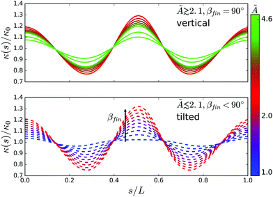
Interestingly, the final ring shape is slightly deformed from the circular one, as illustrated in Fig. 2. A reference circle of the same length L = Nl0 (and radius R0 = L/(2π)) is drawn for comparison. The shape of the settling ring is then oval, with the largest curvature at the bottom, slightly smaller at the top and two curvature minima at both sides.
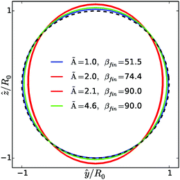 | ||
| Fig. 2 Oval shapes of exemplary tilted and vertical structures (color lines) and a reference circle of radius R0 (dashed black line). Here ŷ and ẑ denote coordinates in the plane determined by the tilt angle βfin. The colors are the same as in Fig. 3. The chosen ovals correspond to the extreme cases in the top and bottom panels of Fig. 3. | ||
This is illustrated in Fig. 3 where the curvature κ(s) along the chain is plotted as a function of the arc length s. The curvature is normalized with the curvature κ0 = 2π/L of the reference circle.
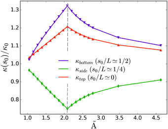
The oval shape resembles a post-buckling deformation of an elastic ring under hydrostatic pressure.67,68 Interestingly, as seen in Fig. 4, the dependence of the curvature at the top and bottom of the sedimenting ring on the bending stiffness à is non-monotonic, with a sharp maximum at à = A1, i.e. at the point where the final tilt of the ring becomes 90°. This is then the point at which the sedimenting rings attain the most deformed shape.
Actually, the rings are not flat – they are also deformed out of plane. In Fig. 1, the final tilt angle βfin has been determined as the average taken over triplets of beads and over time. The ‘error bars’ in the plot correspond to deviations from the average, evaluated in the same way as the standard deviation.
The existence of a stable tilt angle for a sedimenting elastic ring, found here, is very interesting, especially when compared with the rigid case. The rigid ring settles without changing the initial orientation. This is a consequence of the reflectional symmetry of the ring, superposed with time reversal. An analogous result is known for two identical particles in a tilted configuration. Interestingly, the conclusion that the orientation of disc-like objects in sedimentation depends on their stiffness is consistent with experiments on red blood cells. In ref. 25 it is shown that red blood cells, which are of a disk-like biconcave shape, show enhanced preference for vertical sedimentation as their membrane is chemically stiffened, which is in qualitative agreement with our numerical findings shown in Fig. 1.
3.2 Chains of medium stiffness, 0.3 ≲ Ã ≲ 1
As mentioned in the previous section, as the bending stiffness is decreased, the final tilt angle becomes smaller. This continues down to à = A2 ≈ 1 and the corresponding βcrit ≈ 50°, at which point the tilted ring solution becomes destabilized. When à decreases below 1, the ring oscillates around a certain tilt angle, with the amplitude increasing with the decreasing Ã. This mode is called tilted swinging.The dynamics becomes richer when the chain stiffness à is decreased below 0.85. In this case hydrodynamic forces overcome elastic ones sufficiently to induce the swinging mode of the chain, see the snapshots taken in the center-of-mass (CM) frame shown in Fig. 5 and Movies 2a, b and c in the ESI.† Initially, the chain behaves as in the stiffer cases, i.e. the tilt angle increases. At a critical value of the tilt angle§, the ring becomes unstable and the chain enters a periodic swinging motion with its center of mass remaining in a vertical plane. One cycle of the motion involves transition through a set of configurations, from a bent 3D shape to its mirror image. The formerly mentioned vertical plane constitutes also a plane of symmetry for each transient shape.
 | ||
| Fig. 5 From left to right: snapshots taken in the CM frame showing the motion of the swinging mode, N = 60. Gravity points down. | ||
For even less stiff chains, Ã ≲ 0.6, the swinging motion also emerges at the beginning but then destabilizes after a certain time. Eventually, the chain freezes in one of the transient shapes, and its settling down is accompanied by a spinning around its vertical axis. The chain remains in this attracting state till the end of the simulation. Snapshots of the motion are depicted in Fig. 6 and Movie 3a (ESI†). The emergence of this mode is shown in Movie 3b in the ESI.† This sedimentation mode will be further referred to as frozen rotating.
 | ||
| Fig. 6 From left to right: snapshots taken in the CM frame showing the rotation of the frozen rotating mode, N = 60. Gravity points down. | ||
Summarizing, the initially tilted sedimenting elastic ring either adopts a fixed oval configuration (for à > A2) or enters a periodic swinging motion (for à ≲ A2). The swinging motion seems to be very stable. However, when à is further decreased, the swinging may destabilize and the ring may adopt the frozen rotating mode, characterized by completely different dynamics.
For even less stiff loops, with à ≲ 0.4, the initial behavior of the ring remains the same – the ring enters a more or less regular swinging type of motion. But later, there emerge also other long-lasting sedimentation modes. Simulations scanning thoroughly the values of bending stiffness à in the narrow range between 0.3 and 0.4 were carried out, and yielded the existence of as many as three other sedimentation modes, described in detail below. They were detected at different (but very close to each other) values of Ã.
For example, for à ≃ 0.38 the chain adopts another fixed configuration, resembling a bent figure eight, which rotates around the vertical axis. This shape brings up an analogy to the parabolic shape of elastic rods in homogeneous Stokes flow69 or to sedimenting teardrop-shaped red blood cells.29 Snapshots of the motion, illustrating the bent figure eight mode, are presented in Fig. 7 and Movie 4 in the ESI.†
 | ||
| Fig. 7 From left to right: snapshots taken in the CM frame showing the rotation of the bent figure eight mode, N = 60. Gravity points down. | ||
For a bending stiffness smaller by only 0.002 (Ã = 0.378) we find another periodic mode – tank treading motion. The loop rotates without changing its shape, and the beads translate along the loop. Snapshots of the tank treading motion are given in Fig. 8 and Movie 5 in the ESI.† One should note here that in Movies 2b, 3a, b and 4 (ESI†) the CM motion has been subtracted for clarity. The same has been done in Fig. 8 and Movie 5 (ESI†), but, in addition, the spinning of the system has also been subtracted. This revealed a very characteristic tank treading motion, that is motion in which each bead follows exactly the same trajectory while moving along the loop.
 | ||
| Fig. 8 From left to right: snapshots taken in the CM frame showing the flow of beads in the tank treading mode, N = 60. Gravity points down. Here, the spinning of the system has been subtracted. | ||
Finally, in this medium bending stiffness range, simulations yield another periodic mode, e.g. for à ≃ 0.35. In this case, the shape of the loop significantly deforms. The subsequent configurations possess two vertical planes of symmetry, perpendicular to each other. In such a symmetric flapping mode the first half of the periodic cycle can be mapped onto the second one by a rotation of 90 degrees around the vertical axis. The center of mass oscillates only in a vertical direction. Examples of the flapping motion are shown in Fig. 9 and Movies 6a and b in the ESI.†
 | ||
| Fig. 9 From left to right: snapshots taken in the CM frame showing the motion of the flapping mode, N = 60. Gravity points down. | ||
Summing up, the simulations performed in this section for the bending stiffness à falling within the range 0.3–0.6 produced one of five sedimentation modes: swinging, frozen rotating, bent figure eight, tank treading, and flapping.
3.3 Chains of low stiffness, Ã ≲ 0.3
At low bending stiffnesses the chain is sufficiently soft to spontaneously collapse into a compact structure. Eventually, though, periodic modes emerge again. The chain adopts a doughnut-like shape made of two (e.g. for à = 0.25) or three (e.g. for à = 0.23) loops, as shown in Fig. 10, 11 and 12b and c. The toroidal structures orient more or less horizontally, with tightly intertwined loops swirling around each other. This motion is accompanied by spinning around the vertical axis and precession. With reference to the torus knot nomenclature, the two modes will be called![[scr T, script letter T]](https://www.rsc.org/images/entities/char_e533.gif) 2,1, and
2,1, and ![[scr T, script letter T]](https://www.rsc.org/images/entities/char_e533.gif) 3,1 (the modes are obviously not knotted, which is indicated by 1 in the subscripts, see Appendix A) for the two, and three looped configurations, respectively. In Fig. 12b and c, examples of characteristic shapes are displayed. Fig. 10 and 11 present snapshots of the swirling motion typical for the
3,1 (the modes are obviously not knotted, which is indicated by 1 in the subscripts, see Appendix A) for the two, and three looped configurations, respectively. In Fig. 12b and c, examples of characteristic shapes are displayed. Fig. 10 and 11 present snapshots of the swirling motion typical for the ![[scr T, script letter T]](https://www.rsc.org/images/entities/char_e533.gif) 2,1, and
2,1, and ![[scr T, script letter T]](https://www.rsc.org/images/entities/char_e533.gif) 3,1 sedimentation modes, which are also shown in Movies 7 and 8 in the ESI.†
3,1 sedimentation modes, which are also shown in Movies 7 and 8 in the ESI.†
 | ||
Fig. 10 From left to right: snapshots taken in the CM frame showing the swirling of the toroidal ![[scr T, script letter T]](https://www.rsc.org/images/entities/char_e533.gif) 2,1 mode, N = 60. Gravity points down. 2,1 mode, N = 60. Gravity points down. | ||
 | ||
Fig. 11 From left to right: snapshots taken in the CM frame showing the swirling of the toroidal ![[scr T, script letter T]](https://www.rsc.org/images/entities/char_e533.gif) 3,1 mode, N = 60. Gravity points towards the reader. 3,1 mode, N = 60. Gravity points towards the reader. | ||
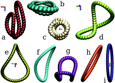 | ||
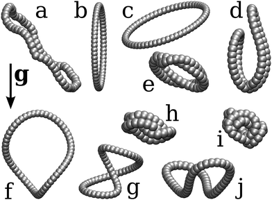
Fig. 12 Typical configurations for sedimentation modes of a closed chain made of N = 60 beads: (a) bent figure eight (frozen shape with very slow rotation), (b) toroidal, swirling ![[scr T, script letter T]](https://www.rsc.org/images/entities/char_e533.gif) 2,1, (c) toroidal, swirling 2,1, (c) toroidal, swirling ![[scr T, script letter T]](https://www.rsc.org/images/entities/char_e533.gif) 3,1, (d) tank treading, (e) frozen rotating, (f) swinging, (g) flapping, (h) tilted, and (i) vertical. In (a), (b), and (d)–(i) gravity points downwards, and in (c) gravity points perpendicularly, towards the observer, in agreement with Fig. 5–11. 3,1, (d) tank treading, (e) frozen rotating, (f) swinging, (g) flapping, (h) tilted, and (i) vertical. In (a), (b), and (d)–(i) gravity points downwards, and in (c) gravity points perpendicularly, towards the observer, in agreement with Fig. 5–11. | ||
3.4 Summary
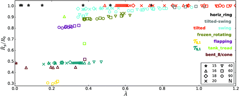
To sum up, the simulations starting from slightly tilted rings with various values of the bending stiffness parameter à revealed the tendency of the system to adopt one of several stationary or periodic sedimentation modes. Fig. 12 shows examples of configurations for all the modes described so far.One could also see, not surprisingly, that the softer the loops are (smaller Ã), the more compact structures they can adopt. This is clearly visible in Fig. 13, where the mean gyration radii ![[R with combining macron]](https://www.rsc.org/images/entities/i_char_0052_0304.gif) g of the sedimentation modes are plotted against the bending stiffness parameter Ã. The gyration radius is defined as:
g of the sedimentation modes are plotted against the bending stiffness parameter Ã. The gyration radius is defined as:  , where ri,cm denotes the distance of the i-th bead center from the center of mass of the chain. The bar indicates an average taken over many periods, and the error bars are evaluated in the standard way based on the time-dependent values. As shown in Fig. 13, the only sedimentation mode for which Rg significantly changes in time is the flapping mode.
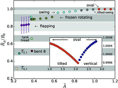 | ||
Fig. 13 The mean relative gyration radius, ![[R with combining macron]](https://www.rsc.org/images/entities/i_char_0052_0304.gif) g/R0, of sedimentation modes versus the bending stiffness Ã. The modes are reached in simulations starting with tilted rings at β0 = 16°, after a relaxation phase. The inset shows the continuation of the main plot at higher Ã, with the vertical scale deeply zoomed in. This allows one to see the slight change in shape of both tilted and vertical modes with increasing à (cf.Fig. 3 and 4). g/R0, of sedimentation modes versus the bending stiffness Ã. The modes are reached in simulations starting with tilted rings at β0 = 16°, after a relaxation phase. The inset shows the continuation of the main plot at higher Ã, with the vertical scale deeply zoomed in. This allows one to see the slight change in shape of both tilted and vertical modes with increasing à (cf.Fig. 3 and 4). | ||
The values of the mean gyration radii vary significantly between the different modes – e.g. for the ![[scr T, script letter T]](https://www.rsc.org/images/entities/char_e533.gif) 3,1 mode the radius of gyration is roughly three times smaller than that for the original circle (since it contains 3 loops made of the original chain), and the
3,1 mode the radius of gyration is roughly three times smaller than that for the original circle (since it contains 3 loops made of the original chain), and the ![[scr T, script letter T]](https://www.rsc.org/images/entities/char_e533.gif) 2,1 mode has an
2,1 mode has an ![[R with combining macron]](https://www.rsc.org/images/entities/i_char_0052_0304.gif) g roughly two times smaller than the original circle.
g roughly two times smaller than the original circle.
It is worth noting that each sedimentation mode presented here encompasses a family of stationary configurations or periodic motions, parameterized by the bending stiffness Ã. Within the same mode, the time-dependent configurations and orientations observed for different values of à are similar to each other. They repeat in time periodically at similar rates, with only small quantitative differences observed for different values of Ã. To give some examples, a tilted mode describes a family of oval structures with almost flat and circular shapes, tilted at a certain angle βfin with respect to the horizontal direction. However, the value of the βfin angle depends on the bending stiffness parameter, Ã. A frozen rotating mode describes a family of shapes similar to the one in Fig. 12e rotating with slightly different speeds. Within a mode, the shapes and gyration radii slightly differ from each other, depending on Ã.
4 Analysis and discussion of the dynamics
4.1 Basic features of shapes and dynamics
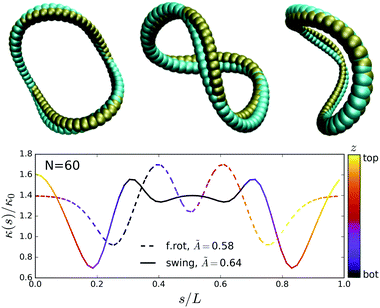
It is worth looking more closely at the shapes of the modes – how exotic they are? For example, as already mentioned before, the oval shapes of tilted and vertical modes resemble the first, in-plane, buckling modes of an elastic ring, e.g. under hydrostatic pressure.67It turns out that also configurations from other sedimentation modes resemble buckled loops formed on purely elastic grounds. For example, the toroidal ![[scr T, script letter T]](https://www.rsc.org/images/entities/char_e533.gif) 3,1 mode appears for the most over-curved examples of deformed bi-layered microrings, jointed arcs of wood, steel wire,70 or on folded paper strips.70,71 Applying less strain to the above mentioned materials yields shapes quite similar to the frozen rotating mode or one of the time-dependent structures of the swinging mode, see Fig. 14 (top panel).70,71 The latter two structures can also be obtained by slightly over-twisting an elastic tube.72
3,1 mode appears for the most over-curved examples of deformed bi-layered microrings, jointed arcs of wood, steel wire,70 or on folded paper strips.70,71 Applying less strain to the above mentioned materials yields shapes quite similar to the frozen rotating mode or one of the time-dependent structures of the swinging mode, see Fig. 14 (top panel).70,71 The latter two structures can also be obtained by slightly over-twisting an elastic tube.72
The above discussion indicates that the shapes observed in our simulations are known from other contexts. However, the spontaneous appearance of these shapes for sedimenting elastic loops, and their dynamics described in Section 3, are in this paper reported for the first time.
It seems remarkable that just a slight change in the chain configuration may lead to a completely different sedimentation mode. In Fig. 14, the configuration of the frozen rotating mode is compared with one of the time-dependent configurations of the swinging mode (with a modified orientation). The differences of shapes are relatively small, but the dynamics are very different, as it is visible in Fig. 5 and 6 and Movies 2b and 3a (ESI†). The corresponding difference in bending stiffness between the two chains is as small as ΔÃ ≃ 0.06.
Another interesting feature of the emerging modes is the diversity of their dynamics. That is, the settling vertical motion may be accompanied by either periodic changes of shape (e.g. swinging, flapping, ![[scr T, script letter T]](https://www.rsc.org/images/entities/char_e533.gif) 2,1,
2,1, ![[scr T, script letter T]](https://www.rsc.org/images/entities/char_e533.gif) 3,1) or rotation of a fixed structure (e.g. bent figure eight, frozen rotating), related to coupling of the translation and rotation.52 In addition, the beads can move along the chain (tank treading). The rotation appears due to the shape chirality. (A chiral structure is a structure that cannot be superposed onto its mirror image.) It means that the chiral isomers rotate in opposite directions, though with identical speeds. The rotation of chiral structures during sedimentation is a well known phenomenon (see e.g.ref. 44 and 73). The question though remains of why the system considered here (chain and fluid) chooses such a chiral geometry, keeping in mind that the initial loop is topologically achiral?
3,1) or rotation of a fixed structure (e.g. bent figure eight, frozen rotating), related to coupling of the translation and rotation.52 In addition, the beads can move along the chain (tank treading). The rotation appears due to the shape chirality. (A chiral structure is a structure that cannot be superposed onto its mirror image.) It means that the chiral isomers rotate in opposite directions, though with identical speeds. The rotation of chiral structures during sedimentation is a well known phenomenon (see e.g.ref. 44 and 73). The question though remains of why the system considered here (chain and fluid) chooses such a chiral geometry, keeping in mind that the initial loop is topologically achiral?
As for the toroidal modes ![[scr T, script letter T]](https://www.rsc.org/images/entities/char_e533.gif) 2,1, and
2,1, and ![[scr T, script letter T]](https://www.rsc.org/images/entities/char_e533.gif) 3,1, it has been already recognized via experiment and simulations that more complicated torus knots also perform a similar characteristic swirling motion.44,73 It is very interesting that such a swirling motion is also typical in completely different systems such as knotted vortex lines74 propagating in inviscid fluid or horizontal coaxial rings made of many separated particles, sedimenting in a very viscous fluid.75,76
3,1, it has been already recognized via experiment and simulations that more complicated torus knots also perform a similar characteristic swirling motion.44,73 It is very interesting that such a swirling motion is also typical in completely different systems such as knotted vortex lines74 propagating in inviscid fluid or horizontal coaxial rings made of many separated particles, sedimenting in a very viscous fluid.75,76
Finally, probably the most intriguing mode, tank treading, is also chiral, and thus rotates. Such a tank treading motion can be found in vesicles and red blood cells.25,28,77–79 Depending on the environmental conditions (pH, in particular), and thus the bending stiffness of the cell's membrane, shape and viscosity contrast, they perform either tank treading, tumbling, or other motions.¶
To verify the generality of the results presented in Section 3, and to test in a simplified way how stable are the sedimentation modes, two additional sets of simulations have been carried out. The goals are to investigate the impact of the chain aspect ratio and the influence of the initial configuration on formation of specific sedimentation modes. As it will be shown in the next two subsections, simulations with various numbers of beads or starting from various initial configurations do not much broaden the already rich family of modes described in Section 3.
4.2 Dynamics of loops with different aspect ratios
To test the impact of the aspect ratio, we perform a set of simulations for elastic loops made of N = 15, 16, 18, 40, and 90 beads. The other conditions are the same as in Section 3. Initially, the loops also form tilted circular rings.In Fig. 15 the mean gyration radius, ![[R with combining macron]](https://www.rsc.org/images/entities/i_char_0052_0304.gif) g, of the output configurations in a given sedimentation mode is plotted against the bending stiffness parameter Ã, for various N (including the results for N = 60, shown in Fig. 13). The gyration radii are scaled with the radii R0 of circles made of the corresponding numbers of beads. It is obvious that if different numbers N of smaller or larger beads were located along the same curved loop, than Rg/R0 would not depend on N. Movie 9 (ESI†) illustrates that for the frozen rotating motion, the loop shapes for different values of N are indeed very similar to each other. A similar property is observed for other sedimentation modes. Therefore, for elastic loops in a given sedimentation mode, the scaled mean gyration radii,
g, of the output configurations in a given sedimentation mode is plotted against the bending stiffness parameter Ã, for various N (including the results for N = 60, shown in Fig. 13). The gyration radii are scaled with the radii R0 of circles made of the corresponding numbers of beads. It is obvious that if different numbers N of smaller or larger beads were located along the same curved loop, than Rg/R0 would not depend on N. Movie 9 (ESI†) illustrates that for the frozen rotating motion, the loop shapes for different values of N are indeed very similar to each other. A similar property is observed for other sedimentation modes. Therefore, for elastic loops in a given sedimentation mode, the scaled mean gyration radii, ![[R with combining macron]](https://www.rsc.org/images/entities/i_char_0052_0304.gif) g/R0, are almost the same for all N. This property is clearly visible in Fig. 15.
g/R0, are almost the same for all N. This property is clearly visible in Fig. 15.
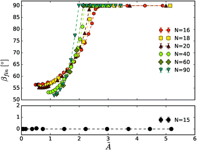
In Fig. 16, the final tilt angle βfin of more stiff loops is shown as a function of bending stiffness Ã. In this way Fig. 1 is extended for a wide range of N.
The scaling with 1/N3 present in à is just an approximation (applicable for thin filaments and small deformations), thus clearly à is not perfectly universal for all values of N. Still though, in Fig. 15 and 16 the modes at various chain lengths emerge in similar ranges of à values, while the corresponding values of unscaled A differ by up to two orders of magnitude.
The main conclusion is that, in general, the chains of various numbers of beads behave similarly in similar à ranges. As an example, in Movie 9 (ESI†) the frozen rotating mode is presented for the loops made of N = 20, 40, 60 and 90 beads. There appears a striking similarity of shapes and rotation speeds.
However, there emerges a critical size (or a critical aspect ratio) below which the dynamics of initially tilted circles become different than in the case of chains with larger numbers of beads. For N ≤ 15 loops maintain circular configurations (with ![[R with combining macron]](https://www.rsc.org/images/entities/i_char_0052_0304.gif) g/R0 = 1, as visible in Fig. 15) and orient horizontally (with βfin = 0, as shown in Fig. 16). This behavior has been observed for a wide range of bending stiffness Ã. Only for very small values of Ã, the loops collapse into a dynamic coil. For N = 15 the ratio of the bead and loop diameters, πd/Nl0, is around 0.35. This seems to be the critical ratio above which the plethora of sedimentation modes may appear.
g/R0 = 1, as visible in Fig. 15) and orient horizontally (with βfin = 0, as shown in Fig. 16). This behavior has been observed for a wide range of bending stiffness Ã. Only for very small values of Ã, the loops collapse into a dynamic coil. For N = 15 the ratio of the bead and loop diameters, πd/Nl0, is around 0.35. This seems to be the critical ratio above which the plethora of sedimentation modes may appear.
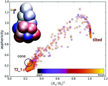
In the simulations with various numbers of beads there emerged only one new sedimentation mode, characteristic for very short chains, and therefore not observed in Section 3. A typical chain configuration for this mode is shown in the inset of Fig. 17. The configuration rotates rigidly. This mode will be further called cone. It seems to be similar to the bent figure eight mode, but with a more compact shape.
Interestingly, elastic loops with a small number of beads, e.g. N = 16, and a small bending stiffness, 0.2 ≲ à ≲ 0.4, tend to jump between two sedimentation modes before they adopt the final stationary shape. Examples of such transitions are shown in Fig. 17 and 18. In these simulations, the tilt angle of the initially tilted ring continues to increase. At a critical value the structure collapses via a transient coil to the swirling ![[scr T, script letter T]](https://www.rsc.org/images/entities/char_e533.gif) 2,1 mode. The structure is quite compact and dense, hence the swirl is not as regular as in the case of larger systems. However, at a certain time the structure straightens again to a tilted ring configuration at a certain tilt angle. These jumps between the modes may repeat several times until the final sedimentation mode is adopted, e.g. a cone mode (see the inset in Fig. 17) or a tank-treading mode (see the inset in Fig. 18). A cartoon illustration of these processes is presented in Fig. 17 and 18, respectively. The tilt angles attained in the transient tilted modes, the times of such jumps and the time to reach the final mode are irregular and can significantly differ from each other when different time instants or values of à are considered. For example, the time to reach the final mode for the dynamics shown in Fig. 17 is much longer than for the motion displayed in Fig. 18.
2,1 mode. The structure is quite compact and dense, hence the swirl is not as regular as in the case of larger systems. However, at a certain time the structure straightens again to a tilted ring configuration at a certain tilt angle. These jumps between the modes may repeat several times until the final sedimentation mode is adopted, e.g. a cone mode (see the inset in Fig. 17) or a tank-treading mode (see the inset in Fig. 18). A cartoon illustration of these processes is presented in Fig. 17 and 18, respectively. The tilt angles attained in the transient tilted modes, the times of such jumps and the time to reach the final mode are irregular and can significantly differ from each other when different time instants or values of à are considered. For example, the time to reach the final mode for the dynamics shown in Fig. 17 is much longer than for the motion displayed in Fig. 18.
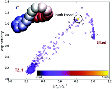 | ||
| Fig. 18 As in Fig. 17 but for N = 16 and à ≃ 0.27. The time from “start” to “finish” is the same as in Fig. 17. | ||
The asphericity used in Fig. 17 and 18 is defined as G3 − (G2 + G1)/2, where G1,2,3 are the eigenvalues of the gyration tensor and G3 ≥ G2 ≥ G1. With this notation, Rg2 = G3 + G2 + G1. Clearly, the asphericity is zero for a sphere. The circles in Fig. 17 and 18 are colored with time as shown in the colorbar legend (e.g. the final state is yellow). In both cases described here, the final mode adopted was either a fixed rigid rotating configuration (cone) or a fixed rigid rotating shape (tank-treading mode, with the beads moving along the shape). By comparing the colors of circles in Fig. 17 and 18, one can see that the tank-treading mode was adopted much faster than the cone mode. The time scales and the color bars in both figures are the same. The blue circles indicate time instants close to the beginning of the simulation, while the orange and yellow ones close to the end of the simulation. In Fig. 17, only the orange circles are visible close to both transient modes, and the yellow ones close to the final cone mode, which indicates a very long time needed to approach the final mode. On the contrary, in Fig. 18, only the blue circles are visible close to both transient modes, while all the orange and yellow circles are superimposed on a single one, corresponding the final tank-treading mode. This indicates a very short time needed to approach the final mode during this simulation.
The above results illustrate that in the elastic loop dynamics, there exist transient sedimentation modes in addition to the final ones which seem to be stable. The time scales of such transients can be short or very long. These findings are important from a fundamental point of view and essential for practical applications.
4.3 Dynamics for different initial configurations
In this section, another set of simulations is performed to test the impact of the initial configuration. Dynamics of elastic loops made of N = 60 beads are considered, starting from either irregular configurations or from configurations representing individual sedimentation modes. The other parameters are the same as in Section 3. All the simulations are again carried out for various values of bending stiffness Ã.Fig. 19 presents the initial configurations and orientations used in the simulations performed in this section. The geometries in Fig. 19b–h and j are representatives of the sedimentation modes discussed in Section 3. The structure in Fig. 19i is an arbitrary random coil obtained also during one of the previous simulations. Finally, the structure in Fig. 19a was obtained from a single run of Brownian dynamics (performed in the standard way, e.g. as described in our previous work44).
The most important results are sketched in Fig. 20. This diagram shows which sedimentation mode finally takes place, depending on the initial configuration and bending stiffness. The colors of tiles in this diagram represent the final sedimentation modes as marked in the colorbar legend (note that these colors match also the colors used in Fig. 12, 13 and 15). The vertical axis corresponds to the initial configurations, and the horizontal axis to the sample values of à used in the simulations.|| For example, the loop starting from one of the bent figure eight configurations (shown in Fig. 19d) with à = 0.87 ends up in the toroidal ![[scr T, script letter T]](https://www.rsc.org/images/entities/char_e533.gif) 2,1 mode.
2,1 mode.
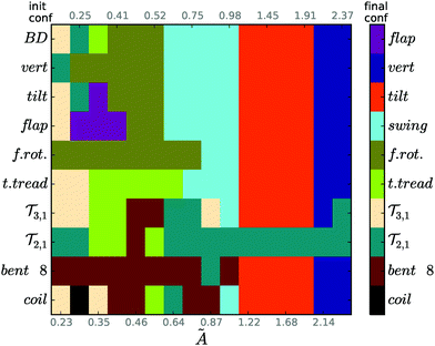 | ||
| Fig. 20 A sample schematic diagram showing the final sedimentation mode (colors), depending on the initial configuration (rows) for the indicated values of bending stiffness à (columns). N = 60 and the colors are coded in the bar legend, consistently with the colors in Fig. 12. | ||
For rather stiff loops, almost all the initial configurations – except for ![[scr T, script letter T]](https://www.rsc.org/images/entities/char_e533.gif) 2,1 – attain the vertical mode (for à ≳ 2), and the tilted mode (for 1 ≲ à ≲ 2), as shown in Fig. 20 and Movie 10 (ESI†). The only outlier which survives in the range of medium and larger bending rigidities, even for the most stiff cases (à ≳ 2), is the
2,1 – attain the vertical mode (for à ≳ 2), and the tilted mode (for 1 ≲ à ≲ 2), as shown in Fig. 20 and Movie 10 (ESI†). The only outlier which survives in the range of medium and larger bending rigidities, even for the most stiff cases (à ≳ 2), is the ![[scr T, script letter T]](https://www.rsc.org/images/entities/char_e533.gif) 2,1 mode, as illustrated in Fig. 20. It is probably stabilized by strong hydrodynamic interactions between the two loops it forms (strong enough to overcome the elastic strain).
2,1 mode, as illustrated in Fig. 20. It is probably stabilized by strong hydrodynamic interactions between the two loops it forms (strong enough to overcome the elastic strain).
For à ≲ 0.98, the diagram in Fig. 20 is full of colors, which vary between rows and columns. This property illustrates complexity of the dynamics. For medium bending rigidities à ∼ 0.64–0.98, the swinging mode seems to be typical: it emerges from the majority of initially rather extended structures. For more flexible loops, à ∼ 0.35–0.52, the most typical sedimentation modes are frozen rotating (surviving or emerging from other, rather extended structures), as well as tank treading and bent figure eight (surviving or emerging from other, typically rather compact initial configurations). The frozen rotating and bent figure eight modes survive in the wide ranges of lower and medium bending rigidities. For the smallest investigated à = 0.23, the most typical is the most compact ![[scr T, script letter T]](https://www.rsc.org/images/entities/char_e533.gif) 3,1 mode.
3,1 mode.
Looking at a single column in Fig. 20, e.g. Ã = 0.64, we observe that depending on the initial structure, the chain adopts one of several sedimentation modes, e.g. swinging, frozen rotating, tank treading, bent figure eight**, or ![[scr T, script letter T]](https://www.rsc.org/images/entities/char_e533.gif) 2,1.
2,1.
Such multi-stability is generic. Starting from different initial configurations, different sedimentation modes can be reached for the same elastic loop in the same fluid. In Fig. 20, this property is represented by different colors visible in each column, and the corresponding significant differences between the rows.
5 Conclusions
We have shown that an elastic loop, settling in a viscous fluid in the low-Reynolds-number regime, tends to reach a stationary configuration or one of the characteristic periodic motions, superposed with center-of-mass translation. Surprisingly, we have discovered a diversity of such sedimentation modes, depending on the loop bending stiffness and initial configuration. The modes form spontaneously after a certain relaxation time.More stiff loops can form almost flat stationary oval shapes (close to the equilibrium circular one), vertical or tilted. The more stiff the loop, the closer it is to a vertical orientation during settling, which is in close analogy to the experimental findings on chemically stiffened red blood cells.25 In the whole range of the investigated bending rigidities, periodic motions of complicated bent shapes have been found. Some of them involve time-dependent deformations of the loop shape. The others correspond to a fixed, “frozen” shape which rotates around the vertical axis. In the tank treading mode, there appears an additional motion of the beads along a certain fixed, rotating shape.
The important general conclusion is that for the same value of the bending stiffness, different sedimentation modes may be observed. For the same system: fluid and sedimenting elastic loop, there exist multiple stable (or at least long-lasting) periodic motions or stationary configurations. This property holds for all considered values of the bending stiffness Ã. However, a particularly rich diversity of many different modes is observed for more flexible loops with à ≲ 1. These findings illustrate that in a sedimenting dilute suspension of identical very elastic loops, many different sedimentation modes can coexist.
Moreover, the sedimentation modes are sensitive to small changes of the bending stiffness à of the sedimenting loop. This feature may be of practical significance. If elastic loops are put in a centrifuge, the value of à ∼ 1/F0 can be easily changed by tuning the centrifugal force F0. In this way the desired sedimentation modes can be triggered.
Some of the sedimentation modes, such as tilted or some of the swinging ones, are non-symmetric and as a result there appears a net horizontal drift. This property might be used in practice for sorting.
In general, the existence of different sedimentation modes found in this paper is of great significance for many biological, medical and industrial systems of sedimenting elastic, deformable micro or nano objects. Ring polymers,20–24 red blood cells and vesicles,25–29 proteins or DNA loops11–15 are just a few examples.
Conflicts of interest
There are no conflicts of interest to declare.Appendix
A Toroidal sedimentation modes
The names of the toroidal modes,![[scr T, script letter T]](https://www.rsc.org/images/entities/char_e533.gif) 2,1 and
2,1 and ![[scr T, script letter T]](https://www.rsc.org/images/entities/char_e533.gif) 3,1, refer to the nomenclature introduced in knot theory, where
3,1, refer to the nomenclature introduced in knot theory, where ![[scr T, script letter T]](https://www.rsc.org/images/entities/char_e533.gif) p,q describes a torus knot which winds p times around symmetry axis of a torus and makes q turns around the centerline of the torus. If either p or q equals 1, then
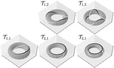
p,q describes a torus knot which winds p times around symmetry axis of a torus and makes q turns around the centerline of the torus. If either p or q equals 1, then ![[scr T, script letter T]](https://www.rsc.org/images/entities/char_e533.gif) p,q is an unknotted structure (called an unknot). Fig. 21 shows examples of the simplest of torus unknots.
p,q is an unknotted structure (called an unknot). Fig. 21 shows examples of the simplest of torus unknots.
There are additional remarks to be made here. Firstly, one can see that ![[scr T, script letter T]](https://www.rsc.org/images/entities/char_e533.gif) 1,1, especially for a small minor radius of the torus, is almost equivalent to the tilted configuration shown in Fig. 19c. Secondly, initial configurations of shapes similar to
1,1, especially for a small minor radius of the torus, is almost equivalent to the tilted configuration shown in Fig. 19c. Secondly, initial configurations of shapes similar to ![[scr T, script letter T]](https://www.rsc.org/images/entities/char_e533.gif) 1,3 in Fig. 21 were also tested in the simulations. They relaxed to a horizontally oriented flat circle and retained this fixed shape and orientation until the end of the simulation.
1,3 in Fig. 21 were also tested in the simulations. They relaxed to a horizontally oriented flat circle and retained this fixed shape and orientation until the end of the simulation.
B Description of the movies
A list of the movies.Movie 1: Short simulations of relatively stiff chains with N = 60 beads, ending in a tilted or vertical sedimentation mode. The bending stiffness à = 1.4, 1.9, and 2.8, starting with a less tilted cyan chain, to vertical dark blue, respectively. For clarity of presentation, the center of mass motion has been subtracted. Gravity points downwards.
Movie 2a: Example of a swinging mode for a chain with N = 60 and à = 0.37. For clarity of presentation, the horizontal center of mass motion, and average vertical speed have been subtracted. Gravity points downwards.
Movie 2b: As in Movie 2a (ESI†), but with the horizontal and vertical center of mass motion subtracted.
Movie 2c: Emergence of a swinging mode. Center of mass motion subtracted, gravity points downwards.
Movie 3a: Example of a frozen rotating mode for a chain with N = 60 beads and à = 0.58. For clarity of presentation, the center of mass motion has been subtracted. Gravity points downwards.
Movie 3b: Emergence of a frozen rotating mode. Center of mass motion subtracted, gravity points downwards.
Movie 4: Example of a figure eight mode for a chain with N = 60 beads and à = 0.23. For clarity of presentation, the center of mass motion has been subtracted. Gravity points downwards.
Movie 5: Example of a tank treading mode for a chain with N = 60 beads and à = 0.52. For clarity of presentation, the center of mass motion and spinning have been subtracted. Gravity points downwards.
Movie 6a: Example of a flapping mode for a chain with N = 60 beads and à = 0.28. For clarity of presentation, the horizontal center of mass motion and average vertical speed have been subtracted. Gravity points downwards.
Movie 6b: As in Movie 6a (ESI†), but with the center of mass motion subtracted.
Movie 7: Example of a ![[scr T, script letter T]](https://www.rsc.org/images/entities/char_e533.gif) 2,1 mode for a chain with N = 60 beads and à = 0.23. For clarity of presentation, the center of mass motion has been subtracted. Gravity points downwards.
2,1 mode for a chain with N = 60 beads and à = 0.23. For clarity of presentation, the center of mass motion has been subtracted. Gravity points downwards.
Movie 8: Example of a ![[scr T, script letter T]](https://www.rsc.org/images/entities/char_e533.gif) 3,1 mode for a chain with N = 60 beads and à = 0.23. For clarity of presentation, the center of mass motion has been subtracted. Gravity points downwards.
3,1 mode for a chain with N = 60 beads and à = 0.23. For clarity of presentation, the center of mass motion has been subtracted. Gravity points downwards.
Movie 9: Frozen rotating mode for chains with various numbers of beads: N = 20, Ã = 0.59 (green), N = 40, Ã = 0.63 (cyan), N = 60, Ã = 0.23 (blue), N = 90, Ã = 0.45 (purple). The center-of-mass motion has been subtracted.
Movie 10: Example transitions from four different modes – ![[scr T, script letter T]](https://www.rsc.org/images/entities/char_e533.gif) 31 (top left), bent figure eight (top right), tank treading (bottom left), compact coil (bottom right) – to the final tilted mode. Middle panel: all four simulations overlaid onto each other. In all the simulations N = 60, Ã= 1.91, and gravity points down. After 2/3 of the video the frame rate is increased 4 times.
31 (top left), bent figure eight (top right), tank treading (bottom left), compact coil (bottom right) – to the final tilted mode. Middle panel: all four simulations overlaid onto each other. In all the simulations N = 60, Ã= 1.91, and gravity points down. After 2/3 of the video the frame rate is increased 4 times.
Acknowledgements
M. G.-S. and P. S. were supported in part by Narodowe Centrum Nauki under grant 2015/19/D/ST8/03199. We thank Tony Ladd, Jason Butler and Marek Bukowicki for helpful discussions. Figures and movies visualizing the results of simulations were prepared with the help of the VMD package.82References
- M. C. Lagomarsino, I. Pagonabarraga and C. Lowe, Phys. Rev. Lett., 2005, 94, 148104 CrossRef.
- M. Manghi, X. Schlagberger, Y.-W. Kim and R. R. Netz, Soft Matter, 2006, 2, 653–668 RSC.
- I. Llopis, I. Pagonabarraga, M. C. Lagomarsino and C. P. Lowe, Phys. Rev. E: Stat., Nonlinear, Soft Matter Phys., 2007, 76, 061901 CrossRef CAS.
- L. Li, H. Manikantan, D. Saintillan and S. E. Spagnolie, J. Fluid Mech., 2013, 735, 705–736 CrossRef.
- G. Saggiorato, J. Elgeti, R. G. Winkler and G. Gompper, Soft Matter, 2015, 11, 7337–7344 RSC.
- A. Lindner and M. Shelley, in Fluid-Structure Interactions in Low-Reynolds-Number Flows, ed. C. Duprat and H. Stone, Royal Society of Chemistry, 2015, pp. 168–192 Search PubMed.
- M. Bukowicki and M. L. Ekiel-Jeżewska, Soft Matter, 2018, 14, 5786–5799 RSC.
- B. Marchetti, V. Raspa, A. Lindner, O. Du Roure, L. Bergougnoux, É. Guazzelli and C. Duprat, Phys. Rev. Fluids, 2018, 3, 104102 CrossRef.
- O. du Roure, A. Lindner, E. N. Nazockdast and M. J. Shelley, Annu. Rev. Fluid Mech., 2019, 51, 539–572 CrossRef.
- R. E. Goldstein, T. R. Powers and C. H. Wiggins, Phys. Rev. Lett., 1998, 80, 5232–5235 CrossRef CAS.
- V. Víglasky, F. Valle, J. Adamčík, I. Joab, D. Podhradsky and G. Dietler, Electrophoresis, 2003, 24, 1703–1711 CrossRef.
- E. Ercolini, F. Valle, J. Adamcik, G. Witz, R. Metzler, P. D. L. Rios, J. Roca and G. Dietler, Phys. Rev. Lett., 2007, 98, 058102 CrossRef.
- L. Alonso-Sarduy, C. Roduit, G. Dietler and S. Kasas, FEBS Lett., 2011, 585, 3139–3145 CrossRef CAS.
- M. Alizadehheidari, E. Werner, C. Noble, M. Reiter-Schad, L. K. Nyberg, J. Fritzsche, B. Mehlig, J. O. Tegenfeldt, T. Ambjörnsson, F. Persson and F. Westerlund, Macromolecules, 2015, 48, 871–878 CrossRef CAS.
- Q. Wang, R. N. Irobalieva, W. Chiu, M. F. Schmid, J. M. Fogg, L. Zechiedrich and B. M. Pettitt, Nucleic Acids Res., 2017, 45, 7633–7642 CrossRef CAS.
- B. D. Coleman and D. Swigon, J. Elasticity, 2000, 60, 173–221 CrossRef.
- C. W. Wolgemuth, R. E. Goldstein and T. R. Powers, Phys. D, 2004, 190, 266–289 CrossRef.
- S. Lim, A. Ferent, X. S. Wang and C. S. Peskin, SIAM J. Sci. Comput., 2008, 31, 273–302 CrossRef.
- B. E. Griffith and S. Lim, Commun. Comput. Phys., 2012, 12, 433–461 CrossRef.
- M. Bernabei, P. Bacova, A. J. Moreno, A. Narros and C. N. Likos, Soft Matter, 2013, 9, 1287–1300 RSC.
- M. Z. Slimani, P. Bacova, M. Bernabei, A. Narros, C. N. Likos and A. J. Moreno, ACS Macro Lett., 2014, 3, 611–616 CrossRef CAS.
- P. Poier, C. N. Likos, A. J. Moreno and R. Blaak, Macromolecules, 2015, 48, 4983–4997 CrossRef CAS.
- P. Poier, P. Bačová, A. J. Moreno, C. N. Likos and R. Blaak, Soft Matter, 2016, 12, 4805–4820 RSC.
- I. Chubak, E. Locatelli and C. N. Likos, Mol. Phys., 2018, 116, 2911–2926 CrossRef CAS.
- A. W. L. Jay and P. B. Canham, J. Cell. Physiol., 1972, 80, 367–372 CrossRef CAS.
- J. Beaucourt, F. Rioual, T. Séon, T. Biben and C. Misbah, Phys. Rev. E: Stat., Nonlinear, Soft Matter Phys., 2004, 69, 011906 CrossRef CAS.
- C. Misbah, Phys. Rev. Lett., 2006, 96, 028104 CrossRef.
- C. Misbah, J. Phys. Conf. Ser., 2012, 392, 012005 CrossRef.
- M. Peltomäki and G. Gompper, Soft Matter, 2013, 9, 8346–8358 RSC.
- C. Dupont, A. V. Salsac, D. Barthes-Biesel, M. Vidrascu and P. Le Tallec, Phys. Fluids, 2015, 27, 051902 CrossRef.
- C. Dupont, F. Delahaye, D. Barthes-Biesel and A. V. Salsac, J. Fluid Mech., 2016, 791, 738–757 CrossRef CAS.
- A. Stasiak, V. Katritch, J. Bednar, D. Michoud and J. Dubochet, Nature, 1996, 384, 122 CrossRef CAS.
- E. Ben-Naim, Z. Daya, P. Vorobieff and R. E. Ecke, Phys. Rev. Lett., 2001, 86, 1414 CrossRef CAS.
- A. Belmonte, M. J. Shelley, S. T. Eldakar and C. H. Wiggins, Phys. Rev. Lett., 2001, 87, 114301 CrossRef CAS.
- P. Pieranski, S. Kasas, G. Dietler, J. Dubochet and A. Stasiak, New J. Phys., 2001, 3, 10 CrossRef.
- D. M. Raymer and D. E. Smith, Proc. Natl. Acad. Sci. U. S. A., 2007, 104, 16432–16437 CrossRef CAS.
- B. Audoly, N. Clauvelin and S. Neukirch, Phys. Rev. Lett., 2007, 99, 164301 CrossRef CAS.
- J. I. Sulkowska, P. Sulkowski, P. Szymczak and M. Cieplak, Proc. Natl. Acad. Sci. U. S. A., 2008, 105, 19714–19719 CrossRef CAS.
- R. Matthews, A. Louis and J. Yeomans, EPL, 2010, 92, 34003 CrossRef.
- A. Rosa, M. Di Ventra and C. Micheletti, Phys. Rev. Lett., 2012, 109, 118301 CrossRef CAS.
- S. Kim and D. Palaniappan, AIChE J., 2014, 60, 1517–1522 CrossRef CAS.
- S. Kuei, A. M. Słowicka, M. L. Ekiel-Jeżewska, E. Wajnryb and H. A. Stone, New J. Phys., 2015, 17, 053009 CrossRef.
- P. Szymczak, Sci. Rep., 2016, 6, 21702 CrossRef CAS.
- M. Gruziel, K. Thyagarajan, G. Dietler, A. Stasiak, M. L. Ekiel-Jeżewska and P. Szymczak, Phys. Rev. Lett., 2018, 121, 127801 CrossRef CAS.
- A. D. Bates, A. Maxwell and O. Press, DNA Topology, Oxford University Press, 2005 Search PubMed.
- W. R. Taylor and K. Lin, Nature, 2003, 421, 25 CrossRef CAS.
- P. Virnau, L. Mirny and M. Kardar, PLoS Comput. Biol., 2006, 2, e122 CrossRef.
- P. Dabrowski-Tumanski and J. I. Sulkowska, Proc. Natl. Acad. Sci. U. S. A., 2017, 114, 3415–3420 CrossRef CAS.
- A. M. Słowicka, E. Wajnryb and M. L. Ekiel-Jeżewska, J. Chem. Phys., 2015, 143, 124904 CrossRef.
- H. Lamb, Hydrodynamics, Cambridge University Press, 1993 Search PubMed.
- J. Happel and H. Brenner, Low Reynolds number hydrodynamics, Martinus Nijhoff Publishers, 1983 Search PubMed.
- S. Kim and S. J. Karrila, Microhydrodynamics: principles and selected applications, Courier Corporation, 2013 Search PubMed.
- L. Hocking, J. Fluid Mech., 1964, 20, 129–139 CrossRef.
- B. Felderhof, Phys. A, 1976, 82, 596–610 CrossRef.
- G. Bossis and J. F. Brady, J. Chem. Phys., 1984, 80, 5141–5154 CrossRef CAS.
- B. Felderhof, Phys. A, 1988, 151, 1–16 CrossRef CAS.
- B. Cichocki, B. Felderhof and R. Schmitz, PCH, PhysicoChem. Hydrodyn., 1988, 10, 383–403 CAS.
- A. J. Ladd, J. Chem. Phys., 1988, 88, 5051–5063 CrossRef CAS.
- M. L. Ekiel-Jeżewska and E. Wajnryb, Phys. Rev. E: Stat., Nonlinear, Soft Matter Phys., 2006, 73, 046309 CrossRef.
- P. Szymczak and M. Cieplak, J. Phys.: Condens. Matter, 2011, 23, 033102 CrossRef.
- J. Rotne and S. Prager, J. Chem. Phys., 1969, 50, 4831–4837 CrossRef CAS.
- H. Yamakawa, J. Chem. Phys., 1970, 53, 436–443 CrossRef CAS.
- E. Wajnryb, K. A. Mizerski, P. J. Zuk and P. Szymczak, J. Fluid Mech., 2013, 731, R3 CrossRef.
- L. Landau and E. Lifshitz, Elasticity theory, Pergamon Press, 1975 Search PubMed.
- M. Bukowicki and M. L. Ekiel-Jeżewska, Soft Matter, 2019 Search PubMed , submitted.
- G. I. Taylor, Low Reynolds Number Flows (film), Educational Services Incorporated, Distributor: Encyclopaedia Britannica Educational Corporation, Chicago, Illinois, 1967 Search PubMed.
- B. Wu, Y. Yu and Z. Li, Int. J. Mech. Sci., 2007, 49, 661–668 CrossRef.
- P. A. Djondjorov, V. M. Vassilev and I. M. Mladenov, AIP Conf. Proc., 2011, 1340, 189–202 CrossRef.
- X. Schlagberger and R. R. Netz, Europhys. Lett., 2005, 70, 129–135 CrossRef CAS.
- P.-O. Mouthuy, M. Coulombier, T. Pardoen, J.-P. Raskin and A. M. Jonas, Nat. Commun., 2012, 3, 1290 CrossRef.
- M. A. Dias and B. Audoly, J. Mech. Phys. Solids, 2014, 62, 57–80 CrossRef.
- A. Goriely, J. Thermoelasticity, 2006, 84, 281–299 CrossRef.
- C. Weber, M. Carlen, G. Dietler, E. J. Rawdon and A. Stasiak, Sci. Rep., 2013, 3, 1091 CrossRef.
- F. Maggioni, S. Alamri, C. F. Barenghi and R. L. Ricca, Phys. Rev. E: Stat., Nonlinear, Soft Matter Phys., 2010, 82, 026309 CrossRef CAS.
- M. L. Ekiel-Jeżewska, Phys. Rev. E: Stat., Nonlinear, Soft Matter Phys., 2014, 90, 043007 CrossRef.
- M. Gruca, M. Bukowicki and M. L. Ekiel-Jeżewska, Phys. Rev. E: Stat., Nonlinear, Soft Matter Phys., 2015, 92, 023026 CrossRef.
- T. M. Fischer, Biophys. J., 2004, 86, 3304–3313 CrossRef CAS.
- J. M. Skotheim and T. W. Secomb, Phys. Rev. Lett., 2007, 98, 078301 CrossRef CAS.
- A. Nait-Ouhra, A. Guckenberger, A. Farutin, H. Ez-Zahraouy, A. Benyoussef, S. Gekle and C. Misbah, Phys. Rev. Fluids, 2018, 3, 123601 CrossRef.
- M. Golubitsky, M. Krupa and C. Lim, SIAM J. Appl. Math., 1991, 51, 49–72 CrossRef.
- M. L. Ekiel-Jeżewska, T. Gubiec and P. Szymczak, Phys. Fluids, 2008, 20, 063102 CrossRef.
- W. Humphrey, A. Dalke and K. Schulten, J. Mol. Graphics, 1996, 14, 33–38 CrossRef CAS.
Footnotes |
| † Electronic supplementary information (ESI) available. See DOI: 10.1039/c9sm00598f |
| ‡ See also the generalization in ref. 63. |
| § The critical tilt angle decreases when à becomes smaller. |
| ¶ In a more general context, examples are known of such systems of particles which periodically move along the same relative trajectory while sedimenting in a viscous fluid.80,81 |
| || Not all the performed simulations are shown in Fig. 20. |
| ** In Fig. 5–8, the swinging, frozen rotating, tank treading and bent figure eight modes are shown for exactly the same values of the bending stiffness, Ã = 0.64. In Fig. 9, Ã = 0.25, in Fig. 10, Ã = 1.2, and in Fig. 11, Ã = 0.87. |
| This journal is © The Royal Society of Chemistry 2019 |

