DOI:
10.1039/C8SM02357C
(Paper)
Soft Matter, 2019,
15, 1785-1792
The shape of pinned forced polymer loops
Received
20th November 2018
, Accepted 30th January 2019
First published on 5th February 2019
Abstract
Loop geometry is a frequent encounter in synthetic and biological polymers. Here we provide an analytical theory to characterize the shapes of polymer loops subjected to an external force field. We show how to calculate the polymer density, gyration radius and its distribution. Interestingly, the distribution of the gyration radius shows a non-monotonic behavior as a function of the external force. Furthermore, we analyzed the gyration tensor of the polymer loop characterizing its overall shape. Two parameters called asphericity and the nature of asphericity derived from the gyration tensor, along with the gyration radius, can be used to quantify the shape of polymer loops in theory and experiments.
1 Introduction
Looping is ubiquitous among natural and synthetic polymers.1–6 However, compared to linear polymer chains, the theory of polymer loops is less developed.6–8 Recently, the movement of chromosomes during meiosis in fission yeast was analyzed in great detail.8–11 It was shown that yeast chromosomes form loops and are actively pulled inside the cell in an oscillatory manner.10,12 As a result, the overall shape of the chromosomes, as seen in the experiments, varies from rounded to stretched. It was suggested that these oscillations help to align the chromosomes for recombination.11 That promoted us to develop a theory capable of quantifying the shapes of forced chromosomal loops. Previously, we used an approach of random walks to demonstrate how the pulling force may suppress fluctuations of the polymer loop, but the problem of polymer shape remained unexplored. In this paper, we show how to quantify the shape of pulled polymer loops in a systematic manner. Using a coordinate transformation, the pulled polymer loop setup is mapped to a model of the pinned polymer loop in an external field. We study how the shape of the polymer loop changes under different strengths of the external force field.
Unlike solid objects, the shape of polymers in a fluctuating environment is less visual. The typical size of a polymer can be quantified by its gyration radius.13,14 A number of previous studies was devoted to the description of polymer shapes.15–19 Dating back to 1962, Fixman calculated the gyration radius distribution of polymer chains.20,21 Šolc et al. used the gyration tensor to characterize the shape of a random flight chain.22,23 The shape of pinned polymers was investigated both theoretically24,25 and experimentally26–28 with the development of single molecule imaging techniques. The looping constraint significantly affects the polymer shape. Alim et al. studied the shape of semi-flexible polymer loops without pinning and the external force field.17 Crumpled or elliptical shapes were described depending on whether the polymer was flexible or stiff.17 To the best or our knowledge, no previous work was focused on pinned polymer loops under an external force field.
The paper is organized as follows. In the next section, we introduce the model of pulled polymer loops. We then discuss the segment density function in Section 3. Section 4 is devoted to the gyration tensor and the gyration tensor based shape descriptors, such as gyration radius, asphericity and the nature of asphericity. We discuss our results in the concluding Section 5.
2 Model
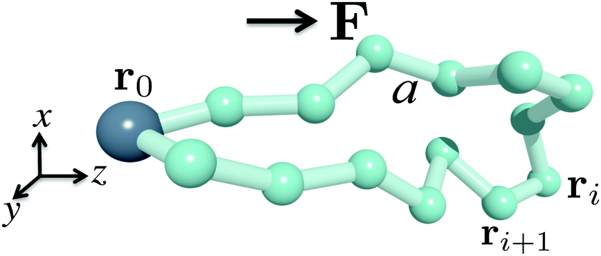
To describe the polymer loop, we employed the freely jointed bead-rod model. We use the bead-rod instead of the more common bead-spring model as it provides a simpler way to take into account the finite extensibility of the polymer, which may be important, for example, to model chromosomes. We will, however, discuss the differences between bead-rod and bead-spring in the Appendix. We consider one polymer loop which is pulled by a single monomer with constant velocity through a viscous medium at a certain temperature. By transferring the coordinate system to the frame co-moving with that bead, we arrive at the setup where one single bead is pinned and a constant velocity of the surrounding fluid with the direction opposite to the pulling direction is imposed on all other beads. We neglect the hydrodynamic interactions14,29 of the beads with each other and model the effect of flow by assuming the Stokes’ law. Thus the external force applied to every bead can be written as F = −ξv. Here, v is the pulling velocity and ξ is the friction coefficient. We can approximate the effect of different pulling velocities by varying the magnitude of the applied force field.
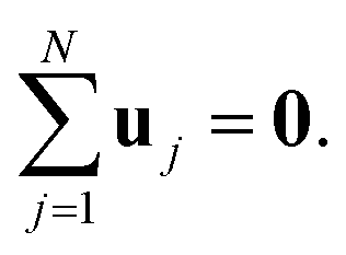
An illustration of a pinned polymer loop is shown in Fig. 1. Without loss of generality, we assume the first bead, whose position is denoted by r0, to be pinned at the origin point, r0 = 0. The looping constraint is thus r0 = rN = 0 where N is the total number of beads. The rod length is denoted by a and the direction of the external force field is chosen along the z direction. The orientation of the jth rod is denoted by the unit vector uj = (rj − rj − 1)/a. With this we can rewrite the looping condition as
| |  | (1) |
 |
| | Fig. 1 Sketch of a bead-rod polymer loop with the first bead pinned. r0 = 0. The force F is pointing in the z-direction. Every two neighboring beads are joint by a rigid rod of length a: |rj+1 − rj| = a. | |
By construction, we have  . Thus the potential energy of the pinned polymer loop configuration can be written as
| | 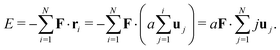 | (2) |
The polymer is immersed in the solution which leads to thermal fluctuations. We characterize the strength of these fluctuations by temperature T. The excluded volume effect will only be discussed briefly in the concluding section. Other interactions such as Coulomb interactions and bending energy are also not considered here.13,14 With the help of this simple setup, we calculate several shape descriptors in the following sections.
3 Segment density function
The configuration of the bead-rod polymer can be considered as a realization of a random walk trajectory which starts from r0 = 0 and comes back to r0 after N steps. According to the central limit theorem,32 the distribution of the ith bead position is well approximated by the Gaussian distribution. We can write| | 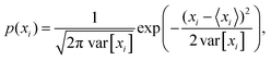 | (3a) |
| |  | (3b) |
where, xi and zi are the coordinate components of the ith bead position. According to the rotational symmetry along the z-axis, the distribution of p(yi) is identical to p(xi).
The mean and variance of every bead position can be written as the following expressions:10,32
| |  | (4a) |
| |  | (4b) |
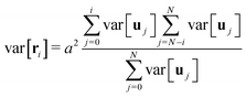
Interestingly, the variance is not given by a simple sum, but a more elaborate construction, which is a consequence of the Brownian Bridge condition. The random walk trajectory has to return to the origin, which makes the variance to be symmetric with respect to the middle of the loop (for details see ref. 10). The mean and variance of every rod orientation uj can be obtained by using the grand canonical ensemble approximation
| | 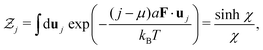 | (5) |
where

is the partition function,
μ is the chemical potential, which can be fixed later by the averaged looping condition

and
χ = (
j −
μ)
Fa/
kBT is a dimensionless parameter. It is now straightforward to calculate the mean and variance of the rod orientation:
| |  | (6a) |
| |  | (6b) |
Using eqn (6a), the chemical potential can be readily calculated as μ = (N + 1)/2. The x and y components of rod orientations can be obtained by symmetry argument and the fact that uj2 = 1. We thus have
| | | var[uj,x] = var[uj,y] = (1 − 〈uj,z2〉)/2. | (7b) |
Here 〈uj,z2〉 = var[uj,z] + 〈uj,z〉2. With the results above, the distribution of the ith bead position eqn (3) can be calculated in a straightforward manner.10 The segment density function as the sum over individual segment distributions, is:
| |  | (8a) |
| |  | (8b) |
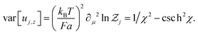
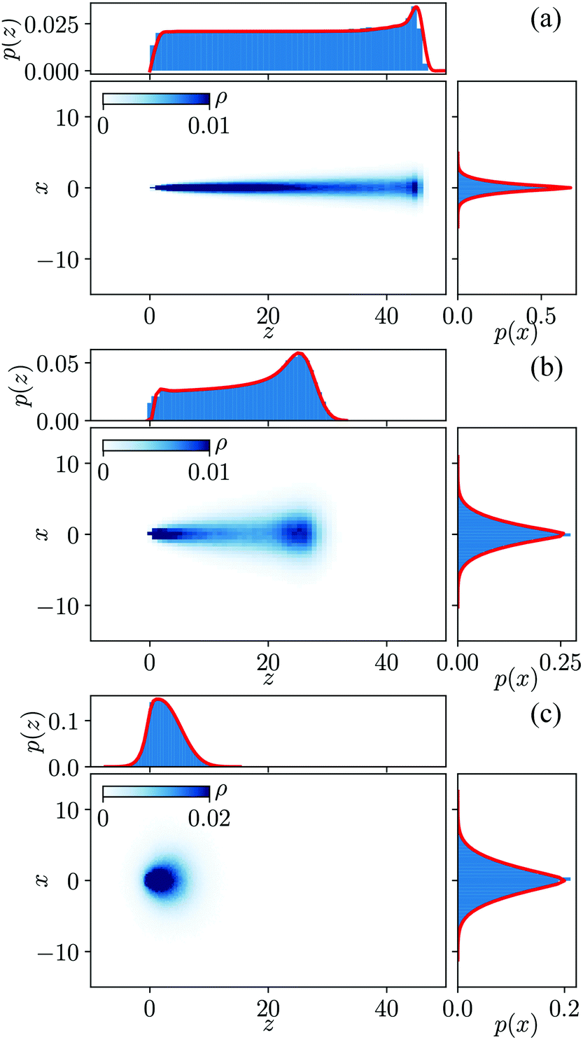
We show in Fig. 2 the segment density distribution of a 3D pinned polymer loop projected on the 2D x–z plane. The upper panel shows the marginal distribution of density along the force direction, while the right panel shows the marginal distribution of density perpendicular to the force direction. The red lines represent our theoretical results above and match very well with the Monte Carlo simulation data shown by blue histograms. Fig. 2(a) shows the case of the pinned polymer loop in a strong external force field. We can see that the polymer shape is fully stretched with most of fluctuations happening at the free end, which corresponds to the middle part of the loop. Fig. 2(b) shows the case of the pinned polymer loop in a moderate force field. The difference between the free end and pinned ends are clearly demonstrated here, which make the shape of the polymer loop look more like a pendulum. The case of the weak external force field is shown in Fig. 2(c), where a droplet-like shape is observed. Having an intuition of the overall shape of pinned polymer loop in an external field, we discuss the gyration tensor in the next section.
 |
| | Fig. 2 The segment density distribution of pinned polymer shape indicated by the color map for (a) strong external force field with F = 1, (b) moderate external force field with F = 0.1, (c) weak external force field with F = 0.01. The unit of the force is rescaled to be kBT/a. ρ indicated by the colormap is the segment density. The panels above and on the right of each density plot are the marginal distributions along the z- and x-axis respectively. The solid red lines are showing the analytical expressions eqn (8). Other parameters are set as follows kBT/a = 1, N = 100. | |
4 The gyration tensor
In order to quantify the shape in a more precise manner, we calculate the three-dimensional gyration tensor of the polymer, which is defined as follows:| | 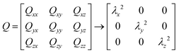 | (9) |
where the elements Qαβ can be written as| | 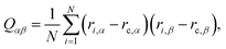 | (10) |
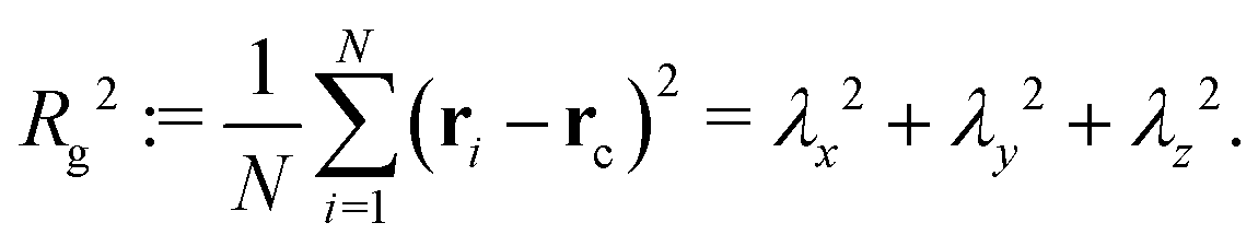
with α, β ∈ {x, y, z} and rc is the center of mass position averaged over the position of all beads  . The right arrow in eqn (9) indicates the diagonalization, and λx2, λy2, λz2 represent the three non-negative eigenvalues of the gyration tensor. Physically, the intuition of the three eigenvalues can be interpreted as the magnitude of three orthogonal axes of the fitted ellipsoid enclosing the polymer loop. For convenience, we sort them by λx2 ≤ λy2 ≤ λz2.
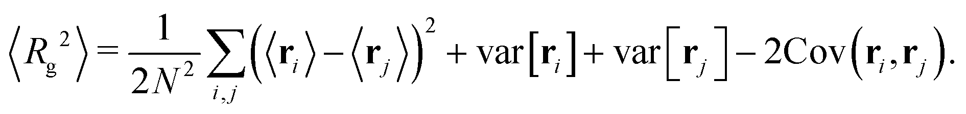
Based on the gyration tensor, the first shape indicator to be discussed is the gyration radius of the polymer, which is defined and can be calculated as follows:
| | 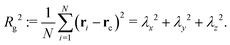 | (11) |
We show how the mean gyration radius 〈Rg2〉 of the polymer loop varies with the strength of the external force field in Fig. 3. The gyration radius increases monotonically with the external force field. Note that the exact results of the two extremes can be easily obtained as 〈Rg2〉 = Na2/12 (F = 0) and 〈Rg2〉 = N2a2/48 (F → ∞). In the zero external force limit, the polymer is a random coil while it is fully stretched in the strong external force limit. For the case in between, we can calculate the mean gyration radius as
| | 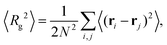 | (12) |
which can be expanded as
| |  | (13) |
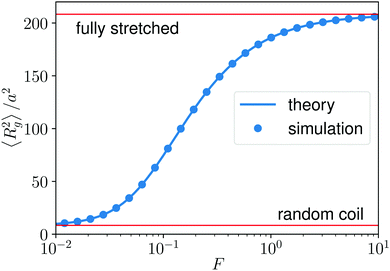 |
| | Fig. 3 The mean of gyration radius square as a function of the strength of the external force field. N = 100, kBT/a = 1. | |
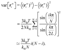
The mean and variance of ri can be obtained from eqn (4) and the covariance can be obtained in a way similar to the variance
| | 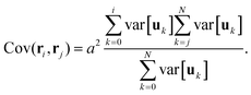 | (14) |
Taken together we arrive at the result shown by the solid line in Fig. 3. To further investigate the fluctuations of the gyration radius, in Fig. 4, we show the normalized distributions of the gyration radius for several strengths of the external force field. Interestingly, the height of the distribution varies non-monotonically with the strength of the external force. In other words, the gyration radius fluctuates most under a moderate force field.
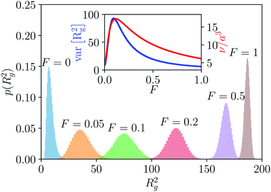 |
| | Fig. 4 The distribution of gyration radius square of the pinned polymer loop under different strength of external force field. The inset shows the width of these distribution (blue curve) and the accessible volume (red curve) as a function of the external force. N = 100, kBT/a = 1. | |
To explain this non-monotonic behavior, we use the concept of accessible volume,33,34 which can be estimated by ν = λxλyλz. We show, in the inset of Fig. 4, the variance of gyration radius, which characterizes the width of the distributions, as a function of the external force field. On top of it, we also plot the accessible volume ν. As we can see the trends of these two curves are very similar, which indicates that the accessible volume can be correlated with the non-monotonic behavior observed in Fig. 4. The discrepancy of these two curves after the maximal point is because of the symmetry break due to the pinning: as we can see in Fig. 2(b), the overall shape of the polymer is an asymmetric rather than a symmetric ellipsoid.
In the weak external force regime, the behavior of the bead-rod system is well approximated by the bead-spring model where the equilibrated spring length equals to the rod length. We have calculated characteristics of the corresponding bead-spring loop in the Appendix. An important fact for the bead-spring model is that the variance of the bead position does not depend on the external force field. Consequently, the radius of the fitted ellipsoid in the direction perpendicular to the external force direction is unchanged in different external force fields, while the radius along the external force direction grows with the external force field. Thus, a larger accessible volume is obtained, and we observe the initial increase in the inset of Fig. 4. However, the finite extensibility of rods becomes important when we further increase the strength of the external force field. The radius of the fitted ellipsoid perpendicular to the force direction is narrowed down and the accessible volume also decreases, which corresponds to the decay part in the inset of Fig. 4.
We next study the asphericity and the nature of asphericity, two other descriptors that commonly used to quantify the shape of polymers. Their definition is based on the gyration tensor.17 The asphericity is defined as
| |  | (15) |
where
![[Q with combining circumflex]](https://www.rsc.org/images/entities/i_char_0051_0302.gif) ij
ij =
Qij −
δijTr
Q/3; and the nature of asphericity is given by
| | 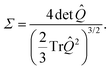 | (16) |
Intuitively, the asphericity Δ is a parameter related to the variance of the three eigenvalues  where λi ∈ {λx, λy, λz} and
 ![[small lambda, Greek, macron]](https://www.rsc.org/images/entities/i_char_e0cc.gif) = (λx + λy + λy)/3. The nature of asphericity Σ is a parameter related to the product of the three eigenvalues
= (λx + λy + λy)/3. The nature of asphericity Σ is a parameter related to the product of the three eigenvalues  . For visualization and comparison purposes we use the rescaled version of these two measures such that
  and arccos
![[thin space (1/6-em)]](https://www.rsc.org/images/entities/char_2009.gif) Σ/3 ∈ [0,π/3].17 The geometrical interpretation of these parameters is illustrated in Fig. 5(b). The limit of Δ = 0 corresponds to a fully spherical object while Δ = 1 describes the shape of the rod-like object, whereas Σ measures whether the object is prolate or oblate.
Σ/3 ∈ [0,π/3].17 The geometrical interpretation of these parameters is illustrated in Fig. 5(b). The limit of Δ = 0 corresponds to a fully spherical object while Δ = 1 describes the shape of the rod-like object, whereas Σ measures whether the object is prolate or oblate.
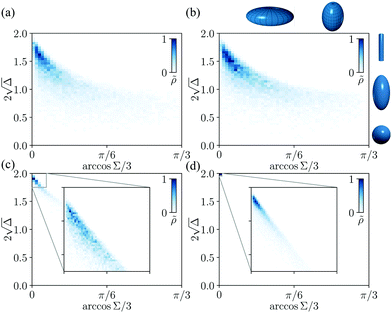 |
| | Fig. 5 The shape of pinned polymer loop distributed over the phase diagram of asphericity and the nature of asphericity. (a) F = 10−3, (b) F = 0.02, (c) F = 0.1, (d) F = 1. ![[small rho, Greek, tilde]](https://www.rsc.org/images/entities/i_char_e0e4.gif) (indicated by the color) is the normalized relative frequency of the polymer shape. Other parameters are set as kBT/a = 1, N = 100. (indicated by the color) is the normalized relative frequency of the polymer shape. Other parameters are set as kBT/a = 1, N = 100. | |
In Fig. 5, we plot the distribution of the polymer shapes on the phase diagram of asphericity and the nature of asphericity. We observe that the shapes are distributed in a smaller region of the parameter space with the increasing force. In addition, the prolate and elongated shapes are preferred largely independent of the external force. The diagrams we plotted here are similar to those obtained for semi-flexible unpinned polymer loops.17
5 Conclusion and discussion
To summarize, we have studied the shape of one pinned and forced polymer loop. Using the position distribution function of each bead, we calculated the segment density function of the whole polymer loop. We found the overall shape of the polymer is rod-like when the external force field is strong, pendulum-like when the external force field is moderate and droplet-like when the external force field is weak. To quantify the shape more precisely, we calculated the three-dimensional gyration tensor of the pinned polymer loop. A detailed study of the gyration radius shows that the mean of gyration radius squared increases monotonically with the strength of the external force field while its variance does not. The gyration radius has a maximal fluctuation in a moderate external force regime. We can explain this observation by using the concept of accessible volume and the Rouse theory of bead-spring polymer approximation in the weak force regime. Finally, we calculated the shape distribution of one pinned polymer loop on the two-dimensional diagram of asphericity and the nature of asphericity, which further highlights the shape of the polymer to be more rod-like even when the external force field is very weak.
Here we focused on one freely jointed bead-rod loop. We did not take into account the excluded volume effect in our model. Our simulation results show that adding the excluded volume does not change the results presented so far qualitatively but leads to the increase in the system size by 5–10 percent (results not shown).
There are several interesting aspects we can further explore in the future. One example is the shape of multiple pinned polymer loops. Our preliminary simulation results show that the non-monotonic behavior in Fig. 4 disappears when there are two or more pinned loops in the system. Note that in fission yeast, there are three pairs of chromosomes pinned at the same point, namely six loops.12 Another topic to explore is the change of polymer shape in the time-dependent force field. For instance, the turning process of the chromosomes during oscillations in fission yeast is an important shape change that carries a biological function and requires further investigations.
Conflicts of interest
There are no conflicts to declare.
Appendix
A Rouse theory of the pinned polymer loop
We mainly discussed the bead-rod polymer loop model in the main text. However, when the external force field is weak, the behavior of the bead-rod system can be approximated by a bead-spring model. For the bead-spring loop, we can use Rouse theory to calculate the stationary and dynamical properties of the polymer. We demonstrate here the calculation of a pinned bead-spring loop in an external force field.
Rouse theory is a theoretical framework to calculate the dynamics of a bead-spring polymer.14,30 We consider a pinned polymer loop modeled by beads and connecting springs. As in our previous discussion of the bead-rod model, the bead labeled by 0 is assumed to be pinned at the origin and there are N beads in total in the loop. Again, the periodic indexing is used. We can write the pinned condition as r0 = rL = 0.
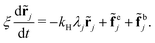
The dynamical equation, which is a Langevin equation in the overdamped regime, can be written as:
| | 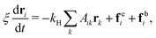 | (17) |
where
ξ is the friction coefficient of a bead in a fluid,
ri is the position of the
ith bead,
kH is the spring constant of a linear Hookean spring.
fei is the external force exerted on beads,
fbi is a typical Brownian force satisfying 〈
fbi,α〉 = 0 and 〈
fbi,α(
t)
fbj,β(
t′)〉 = 2
ξkBTδijδαβδ(
t −
t′). For a pinned loop,
A is a (
N − 1) × (
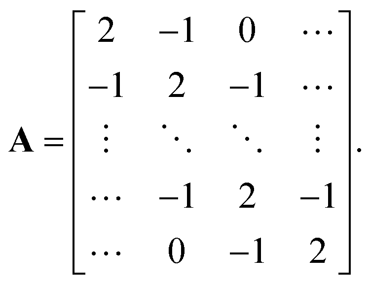
N − 1) connectivity matrix and has the following form
| | 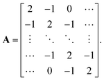 | (18) |
As in the main text, we do not take into account hydrodynamic interactions, bending energy and excluded volume effect in this simple model. For convenience, we use the vector notation and rewrite eqn (17) as:
| | 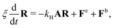 | (19) |
where
R = [
r1,
r2,…,
rN−1]
T. Similar vector notation is also applied for
Fe,
Fb. In order to solve this set of dynamical equations, we first notice that the connectivity matrix
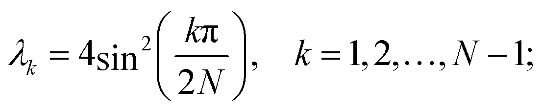
A is a very special type of matrix called tridiagonal Toeplitz matrix,
31 and can be diagonalized exactly. To do this, let us introduce a similarity transform such that
| | | [Ω−1AΩ]jk = Djk = λkδjk, | (20) |
here
Ω is normalized to be a unitary matrix, and
λk are the eigenvalues of matrix
A. The eigenvalues and eigenvectors can be written as follows
| | 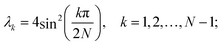 | (21a) |
| | 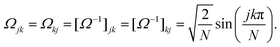 | (21b) |
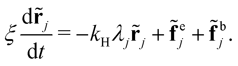
Multiplying both sides of eqn (19) by Ω−1, we arrive at
| | 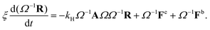 | (22) |
Here
Ω−1AΩ =
D. Using the notation such that
![[R with combining tilde]](https://www.rsc.org/images/entities/b_char_0052_0303.gif)
=
Ω−1R, we get the set of decoupled dynamical equations
| |  | (23) |
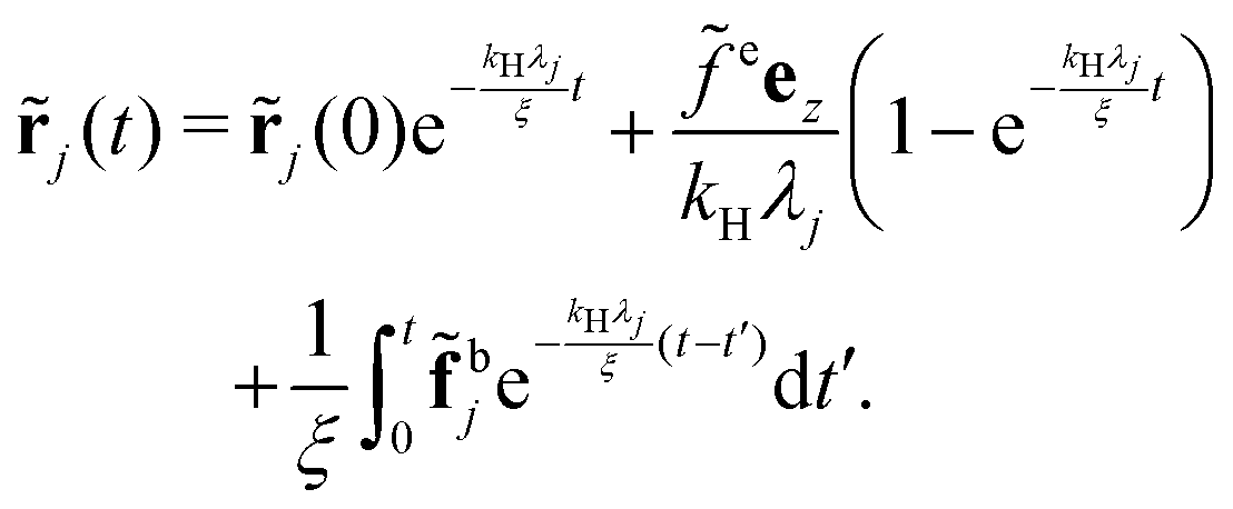
Eqn (23) can be solved easily by standard methods. The general solution can be written as:
| | 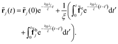 | (24) |
Here the transformed Brownian force
![[f with combining tilde]](https://www.rsc.org/images/entities/b_char_0066_0303.gif) bi
bi also fulfills 〈
![[f with combining tilde]](https://www.rsc.org/images/entities/i_char_0066_0303.gif) bi,α
bi,α〉 = 0 and 〈
bi,α(
t),
bj,β(
t)〉 = 2
ξkBTδijδαβδ(
t −
t′). Given the solution of
eqn (24), the position of each bead can be obtained by the inverse transformation
R =
Ω. In the simple case of constant external force field,
fej =
feez,
eqn (24) can be rewritten as
| | 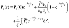 | (25) |
Finally, the bead position can be obtained by the inverse transformation:
| |  | (26) |
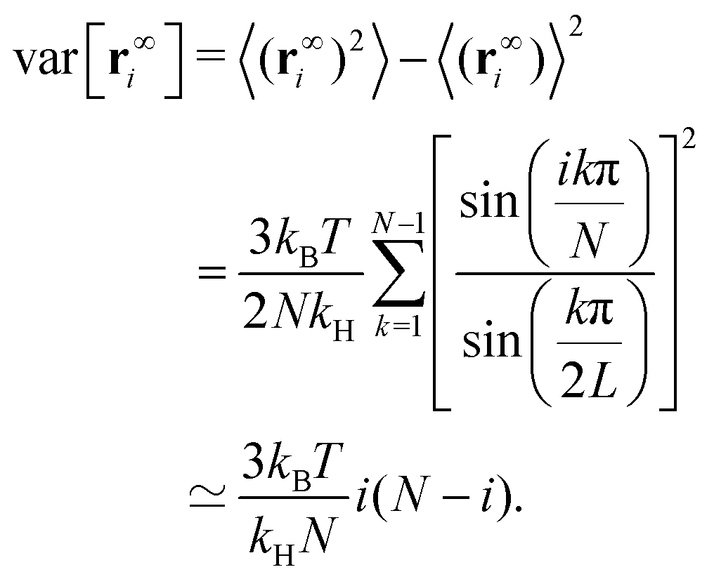
Now the stationary statistics of the polymer, such as the mean and variance of each bead position can be calculated easily. Substituting ![[r with combining tilde]](https://www.rsc.org/images/entities/b_char_0072_0303.gif) j(t) from eqn (25) to eqn (26) and taking the limit t → ∞, we get
j(t) from eqn (25) to eqn (26) and taking the limit t → ∞, we get
| |  | (27) |
The summation over j can be calculated explicitly to get
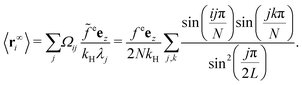
| |  | (28) |
One can clearly see from eqn (28) that 〈r∞i〉 = 〈r∞N−i〉 as expected. In addition, the components of mean position perpendicular to the force field direction are vanished.
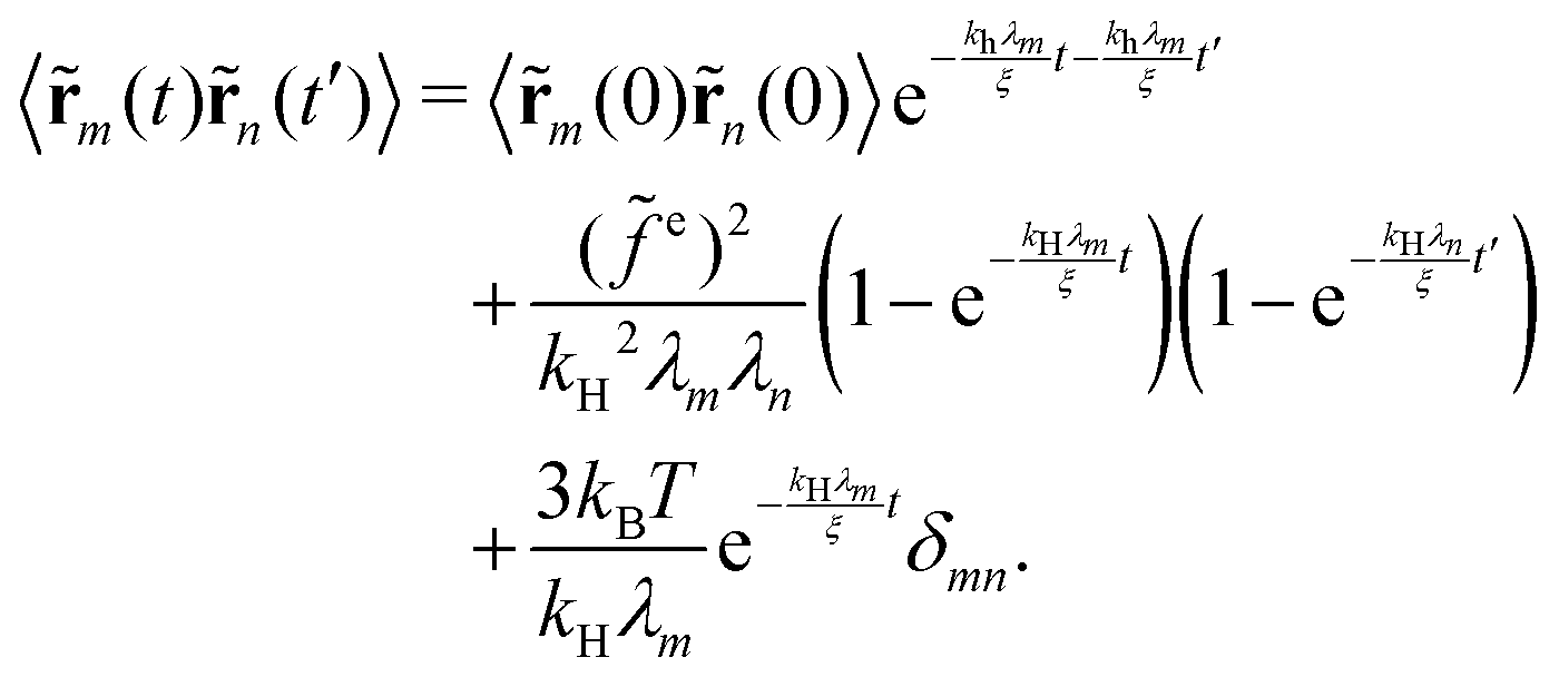
In order to calculate the variance of the bead position, it is nontrivial to first calculate the two-time correlation function of normal coordinate position as
| |  | (29) |
Then the second moment of the bead position can be calculated as:
| |  | (30) |
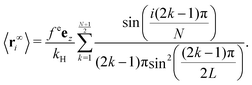
Finally, taking the limit t → ∞, we get the equilibrium variance of the bead position
| |  | (31) |
It is worth mentioning here we also have the symmetry that var[r∞i] = var[r∞N−i]. Moreover, we want to point out that the variance does not depend on the external force. It means that the statistical distance between two beads does not depend on the external force field. This is essentially because infinite extensible Hookean springs are used in the Rouse theory. Furthermore, we also want to remark that the result of eqn (31) is identical to the Brownian bridge result without external force.
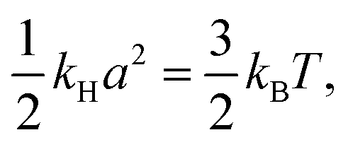
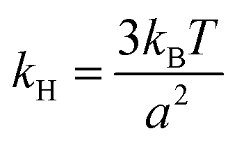
Now we try to fit the Rouse theory to the pinned bead-rod loop. To do this, we take the spring in the bead-spring model as an entropic spring and then relate the spring constant to the length of the rod. If the spring in the polymer is the three-dimensional entropic spring, then the spring constant can be found by the equipartition theorem as
| |  | (32) |
where
a can be interpreted as the equilibrium length of the spring and is set to the length of a rod for the comparison. We obtain

. Plugging it into
eqn (28) and (31) we arrive at
| |  | (33a) |
| |  | (33b) |
where
![[T with combining tilde]](https://www.rsc.org/images/entities/i_char_0054_0303.gif)
=
kBT/Δ
E =
kBT/
fea. Now we can compare these results with the results of the bead-rod model.
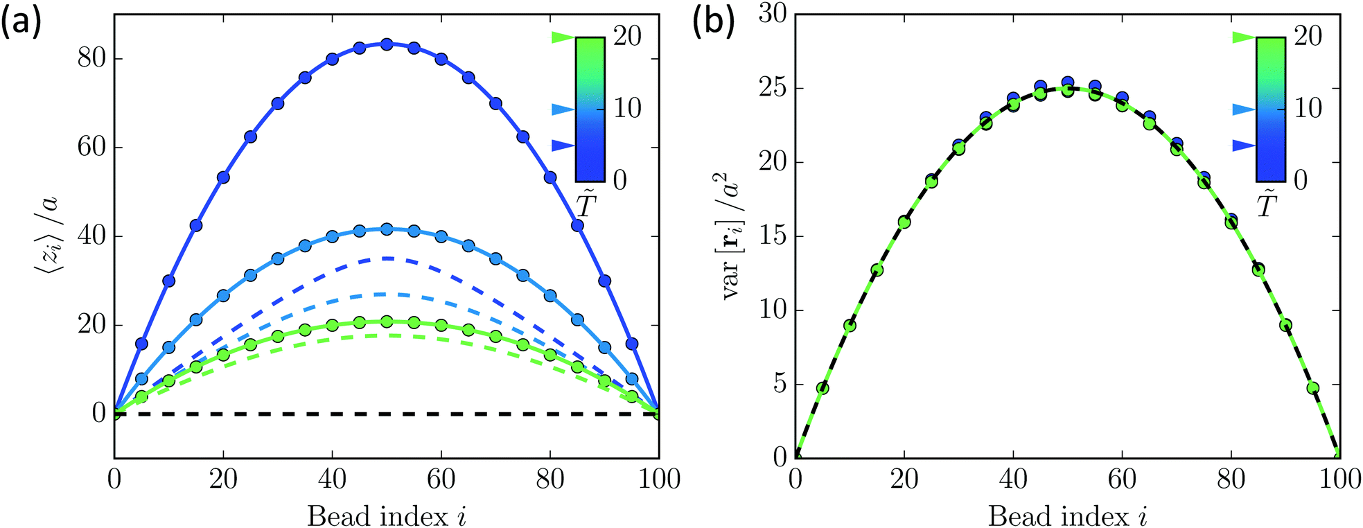
10 From
Fig. 6, we notice that unlike the bead-rod model, the variance of bead position does not depend on the external force field here. This is a fundamental difference between the bead-rod and bead-spring model. As discussed in the main text,
eqn (33) leads to a monotonically increasing accessible volume with the increasing of force. Thus the non-monotonic behavior found in bead-rod model (shown in
Fig. 4) is not observed in the harmonic bead-spring model. Actually, it is possible to analytically calculate the distribution of gyration radius for the bead-spring model, which we will show in our future work. The main results show that the distribution is broadening as the external force increases.
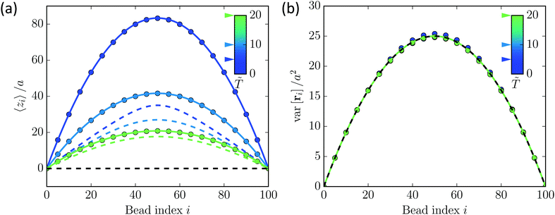 |
| | Fig. 6 The equilibrium mean and variance of bead position for the bead-spring model (dots: simulation results, solid lines: theory), compared with the bead-rod model (dashed lines). (a) Mean bead position of the z component. (b) The variance of bead position. Different colors denote different dimensionless temperature which is indicated in the legend. The black dash line in both (a) and (b) shows the limit of no external force field. | |
Acknowledgements
We would like to acknowledge stimulating discussions with Yen Ting Lin, Hui-Shun Kuan, Lennart Hilbert, Jaeoh Shin and Daniela Froemberg. Open Access funding provided by the Max Planck Society.
References
- J. D. Halverson, J. Smrek, K. Kremer and A. Y. Grosberg, Rep. Prog. Phys., 2014, 77, 022601 CrossRef PubMed.
- D. Richter, S. Goo
![[s with combining umlaut]](https://www.rsc.org/images/entities/char_0073_0308.gif) en and A. Wischnewski, Soft Matter, 2015, 11, 8535–8549 RSC.
en and A. Wischnewski, Soft Matter, 2015, 11, 8535–8549 RSC.
- T. Sakaue, Phys. Rev. Lett., 2011, 106, 167802 CrossRef PubMed.
- J. Kim, Y. Yang and W. Lee, Macromolecules, 2012, 45, 3263 CrossRef CAS.
- A. Rosa and R. Everaers, Phys. Rev. Lett., 2014, 112, 118302 CrossRef PubMed.
- P. S. Lang, B. Obermayer and E. Frey, Phys. Rev. E: Stat., Nonlinear, Soft Matter Phys., 2014, 89, 022606 CrossRef PubMed.
- A. S. Sassi, S. Assenza and P. De L. Rios, Phys. Rev. Lett., 2017, 119, 037801 CrossRef PubMed.
- W. Huang, Y. Lin, D. Frömberg, J. Shin, F. Jülicher and V. Zaburdaev, New J. Phys., 2018, 20, 113005 CrossRef.
- S. K. Vogel, N. Pavin, N. Maghelli, F. Jülicher and I. M. Tolić, PLoS Biol., 2009, 7, e1000087 CrossRef PubMed.
- Y. Lin, D. Frömberg, W. Huang, P. Delivani, M. Chacón, I. M. Tolić, F. Jülicher and V. Zaburdaev, Phys. Rev. Lett., 2015, 115, 208102 CrossRef PubMed.
- M. R. Chacón, D. Petrina and I. M. Tolić, Cell Rep., 2016, 17, 1632–1645 CrossRef PubMed.
- D. Ding, Y. Chikashige, T. Haraguchi and Y. Hiraoka, J. Cell Sci., 1998, 111, 701–712 CAS.
-
P. G. de Gennes, Scaling Concepts in Polymer Physics, Cornell University Press, New York, 1979 Search PubMed.
-
M. Doi and S. F. Edwards, The Theory of Polymer Dynamics, Oxford University Press, Oxford, 1988 Search PubMed.
- M. Bishop and J. Michels, J. Chem. Phys., 1985, 82, 1059–1061 CrossRef CAS.
- O. Jagodzinski, E. Eisenriegler and K. Kremer, J. Phys. I, 1992, 2, 2243–2279 CrossRef CAS.
- K. Alim and E. Frey, Phys. Rev. Lett., 2007, 99, 198102 CrossRef PubMed.
- P. Reiss, M. Fritsche and D. W. Heermann, Phys. Rev. E: Stat., Nonlinear, Soft Matter Phys., 2011, 84, 051910 CrossRef PubMed.
- V. Blavatska and W. Janke, J. Chem. Phys., 2010, 133, 1–7 CrossRef PubMed.
- M. Fixman, J. Chem. Phys., 1962, 36, 306 CrossRef CAS.
- M. Fixman, J. Chem. Phys., 1962, 36, 3123 CrossRef CAS.
- K. Šolc and W. H. Stockmayer, J. Chem. Phys., 1971, 54, 2756 CrossRef.
- K. Šolc, J. Chem. Phys., 1971, 55, 335 CrossRef.
- P. Pincus, Macromolecules, 1976, 9, 386 CrossRef CAS.
- F. Brochard-Wyart, Europhys. Lett., 1995, 30, 387 CrossRef CAS.
- S. Manneville, P. Cluzel, J. Viovy, D. Chatenay and F. Caron, Europhys. Lett., 1996, 36, 413 CrossRef CAS.
- T. Perkins, S. Quake, D. Smith and S. Chu, Science, 1994, 264, 822 CrossRef CAS PubMed.
- T. Perkins, D. Smith, R. Larson and S. Chu, Science, 1995, 268, 83 CrossRef CAS PubMed.
- B. H. Zimm, J. Chem. Phys., 1956, 24, 269 CrossRef CAS.
- P. E. Rouse, J. Chem. Phys., 1953, 21, 1272 CrossRef CAS.
-
C. D. Meyer, Matrix analysis and applied linear algebra, Society for Industrial and Applied Mathematics, Philadelphia, 2000 Search PubMed.
-
W. Feller, An Introduction to Probability Theory and Its Applications, Wiley India Pvt. Limited, New Delhi, 2008 Search PubMed.
- R. M. Sok and H. J. C. Berendsen, J. Chem. Phys., 1992, 96, 4699 CrossRef CAS.
- J. M. Zielinski and J. L. Duda, J. Polym. Sci., Part B: Polym. Phys., 1993, 31, 501 CrossRef.
|
| This journal is © The Royal Society of Chemistry 2019 |
Click here to see how this site uses Cookies. View our privacy policy here. 
 Open Access Article
 This Open Access Article is licensed under a
  a and
Vasily
Zaburdaev
a and
Vasily
Zaburdaev
 . Thus the potential energy of the pinned polymer loop configuration can be written as


 is the partition function, μ is the chemical potential, which can be fixed later by the averaged looping condition
  and χ = (j − μ)Fa/kBT is a dimensionless parameter. It is now straightforward to calculate the mean and variance of the rod orientation:
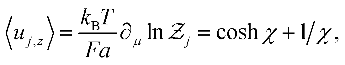


 . The right arrow in eqn (9) indicates the diagonalization, and λx2, λy2, λz2 represent the three non-negative eigenvalues of the gyration tensor. Physically, the intuition of the three eigenvalues can be interpreted as the magnitude of three orthogonal axes of the fitted ellipsoid enclosing the polymer loop. For convenience, we sort them by λx2 ≤ λy2 ≤ λz2.


 where λi ∈ {λx, λy, λz} and
  . For visualization and comparison purposes we use the rescaled version of these two measures such that
  and arccos


 . Plugging it into eqn (28) and (31) we arrive at