
 Open Access Article
 This Open Access Article is licensed under a Creative Commons Attribution-Non Commercial 3.0 Unported Licence
The influence of plasma treatment on the elasticity of the in situ oxidized gradient layer in PDMS: towards crack-free wrinkling†
Bernhard Alexander
Glatz
 ab and
Andreas
Fery
*ac
ab and
Andreas
Fery
*ac
aInstitute of Physical Chemistry and Polymer Physics, Leibniz Institute of Polymer Research Dresden e. V., Hohe Str. 6, 01069 Dresden, Germany. E-mail: fery@ipfdd.de; Fax: +49 351 4658 281; Tel: +49 351 4658 225
bUniversity of Bayreuth Graduate School, University of Bayreuth, Universitätsstr. 30, 95477 Bayreuth, Germany
cChair for Physical Chemistry of Polymeric Materials, Technical University Dresden, Mommsenstr. 4, 01062 Dresden, Germany
First published on 4th December 2018
Abstract
Controlled surface wrinkling is widely applied for structuring surfaces in the micro- and nano-range. The formation of cracks in the wrinkling process is however limiting applications, and developing approaches towards crack-free wrinkles is therefore vital. To understand crack-formation, we systematically characterized the thickness and mechanics of thin layers formed by O2-plasma-oxidation of polydimethyl siloxane (PDMS) as a function of plasma power and pressure using Atomic Force Microscopy Quantitative Nano-mechanical Mapping (AFM-QNM). We found a nearly constant layer thickness with simultaneously changing Young's moduli for both power and pressure screenings. We determined the respective crack densities, revealing conditions for crack-free wrinkling. Thus we could identify correlations between the intensity of plasma treatment and the cracking behavior. The primary cause for crack-suppression is a continuous elasticity gradient starting within the soft bulk PDMS, and rising up to several hundred MPa at the oxidized layer's surface. With mechanical simulations via the Finite Elements Method (FEM) we were able to demonstrate a noticeable difference in maximal stress intensity σmax between a comparable, but theoretical single layer and a gradient interface. A threshold in tensile stress of σcrit = 14 MPa distinguishes between intact and cracked layers.
Introduction
Nano-structured surfaces have recently made great impact on scientific and industrial applications, such as, e.g., adaptive surfaces for improved heat transfer1 or friction reduction.2 These structures share the ability to enhance the properties of existing surface systems,3 or to even create desired properties which an unstructured surface could not exhibit.4 The approaches to fabricate nano-structured surfaces are diverse, such as physical or chemical vapor deposition, chemical etching and photolithography. Photolithography in particular offers high order parameters and low defect densities; nevertheless the method is accompanied by disadvantages such as size limitations, elaborate setups and slow and expensive production.5 Therefore soft-lithographic methods have attracted great interest, as diverse approaches to pattern surfaces are accessible, such as micro-contact-printing,6 laser-interference-lithography,7 or controlled wrinkling, with the last approach being the focus of the present paper.8 Wrinkles develop if a strained elastomer is in strong adhesive contact with a comparably thin, stiff layer. When the two-layer-system is subjected to in-plane compression, wrinkles will form as a consequence of the mechanical mismatch between the thin layer and the thick substrate. Wrinkle assisted pattern formation is cheap, has low instrumentation requirements and is well scalable. Wrinkles can be formed unordered or – by applying a defined stress-field – ordered as well, with well-defined wavelengths.8–12 Wrinkle-structured surfaces have found applications in micro-fluidic devices,13 stretchable electronics,14 optics for micro-lens arrays,15 or templates for the self-assembly of particles.16,17 Controlled surface wrinkling however is accompanied by defect structures, such as line defects and surface cracks. While line defects can in some cases be used for introducing hierarchical patterning,18–23 in most cases especially cracking is undesired and several groups have reported protocols for reducing crack formation. Fig. 1 schematically shows the fabrication of wrinkles, with two possible outcomes: as cracked surfaces (upper path) or uncracked surfaces (lower path). For cracking defects, methods have been presented that are able to avoid such defects, e.g. with UV-curable systems. Xuan et al. synthesized a UV-curable acrylated polydimethylsiloxane with an acrylate cross-linker,24 Park et al. used tetraethylene glycol diacrylate and tetraethylene glycol bis(4-ethenyl-2,3,5,6-tetrafluorophenyl) as the UV-curable polymer,25 and other groups utilized similar systems.26–29 Another approach via chemical treatment of PDMS-surfaces with acids was presented by Watanabe et al.30 For plasma-treated PDMS, Béfahy et al. found crack-free conditions for oxygen plasma treatment on PDMS in a comparable screening setup to ours,31 while Rhee et al. used CHF3 instead of O2.32 Li et al. used initiator-integrated PDMS (iPDMS) to generate the stiff layer in grafting-from polymerization, leading to a stiff film consisting of dense polymer brushes on top of the comparably soft iPDMS.33 However, so far, crack-free wrinkles were achieved by semi-empirical optimization rather than based on structure–property relationships. Initial pointers to the existence of a vertical gradient within the layer were found by Efimenko et al. by assuming a slight modification shift in UVO oxidized PDMS slabs, since this impedes the electron reflectivity on interfaces in near-edge X-ray fine structures (NEXAFS).34 Other hints to a nonlinear slope have been found by various groups using X-ray photoelectron spectroscopy (XPS),35–37 simple specular X-ray reflectivity (XR),34,38 energy-dispersive X-ray analysis (EDXA),39 attenuated total reflection mode FT-IR (ATR-FTIR),34,37 sum frequency generation spectroscopy (SFG)40 or Auger electron spectroscopy (AES).41 All these methods offer the possibility to analyze the physical or chemical modifications of PDMS inside the oxidized layer, but not the mechanical modifications in deep-reaching cross section profiles. Chan et al. were the first to introduce a mechanical model system based on Ultraviolet/Ozone-(UVO) treated PDMS. They postulated a composite layer consisting of a moderately converted intermediate layer topped by a thin, dense silica film.42 The Young's modulus within the intermediate layer is defined as a square function of the local position z on the gradient, resulting in an overall effective Young's modulus Eeff = φ(z)·ESilica. In addition, Sui et al. suggest an exponential decay function to describe the z-change in elasticity over a time-dependent system.43 In this contribution, we correlate for the first time directly the nanostructure and nano-mechanical properties with crack densities for plasma-oxidized PDMS, the most widely used wrinkle-system. We compare our findings to finite element modelling and identify gradient formation in the surface layer as key to crack-free wrinkling. In general, the process to gain crack-free wrinkles can be utilized in all wrinkled surfaces that are desired to be uniform, which is relevant to most practical applications. Those are for example the template-assisted self-assembly (TASA) system as used by us,16,44 grating structures for photons,45 anti-fouling surfaces46–48 as well as surface films that additionally act as barrier layers for the surrounding media.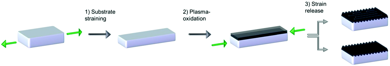 | ||
| Fig. 1 Schematic description of the wrinkling process. In step 1 the elastomeric substrate becomes stretched to a pre-defined strain, followed by the in situ plasma oxidation in step 3. In the final step 3 wrinkles are formed and – in case a critical mechanical tension in the interface of layer and substrate is exceeded – cracks form as well. | ||
Experimental
PDMS preparation
PDMS was prepared by mixing the pre-polymer and curing agent of a Dow Corning Sylgard 184 PDMS Kit in 5![[thin space (1/6-em)]](https://www.rsc.org/images/entities/char_2009.gif) :1 ratio, curing it at RT for 24 h followed by a thermal treatment of 4 h at 80 °C under ambient conditions. Slabs of 4.5 × 1.0 cm were cut out, cleaned with Milli-Q water and dried with nitrogen.
:1 ratio, curing it at RT for 24 h followed by a thermal treatment of 4 h at 80 °C under ambient conditions. Slabs of 4.5 × 1.0 cm were cut out, cleaned with Milli-Q water and dried with nitrogen.
Plasma oxidation
AFM topographical analysis
Oxidized and wrinkled slabs were analyzed in tapping mode (cantilever nominal spring constant = 5 N m−1, nominal resonance frequency = 290 kHz) using a Bruker Dimension Icon as well as a Bruker Dimension FastScan, both running with NanoScope 9.3 Software. Image sizes were 90 × 90 μm with 4096 px resolution and 35 × 35 μm with 1024 px resolution.QNM analysis
Samples were cut in half in the middle. A small section was cut out, clamped in an AFM-holder, and the sample was smoothened along the three-layer-axis with a Cryo-Microtome. The smoothened surfaces were analyzed in QNM-in-air-mode with the same cantilevers and AFMs as described before. Image sizes were 1 × 1 μm with a resolution of 512 px. Every cantilever was calibrated in terms of spring constant, deflection sensitivity and tip radius.Results and discussion
The cracks on the surface usually occur at locations that experience the highest stress intensities, or at points with reduced mechanical properties. In the case of wrinkling, a mechanical mismatch between the layer and the substrate is the reason for periodic deformations of the two-layer-system. Nevertheless, this mismatch also is always accompanied by high in-plane stress at the interface between the layer and the substrate, due to the strongly differing mechanical properties of the layer and the substrate.49 This stress concentration at the interface is most probably the reason for cracking of wrinkled surfaces.50 We therefore investigate such interfaces in our model system of plasma-oxidized and wrinkled PDMS stripes, and discuss reasons thereof. We use Dow Corning's Sylgard 184 in a 1:5 ratio for the substrate, resulting in a Young's modulus measured via indentation of 3.5 ± 0.7 MPa. This is slightly higher than the comparable results from the literature, measured via tensile testing.51
First, we systematically tune the intensities of oxygen plasma via two parameters: the nominal power of the plasma cleaner and the oxygen pressure inside the plasma chamber, while all other parameters but the studied one are kept constant. We investigate the effect on the wrinkle size and crack density on pre-strained and wrinkled PDMS stripes as shown in Fig. 2. We strain the samples by 60% – a comparatively large strain – and subsequently plasma-treat them in order to achieve a high mechanical in-plane stress in the freshly formed two-layer-system. In the eventual pre-strain relaxation step, wrinkles form as well as surface cracks. The wrinkles then are analyzed via 2D-Fourier Transformation (2D-FT) as schematically described in Fig. 2a, showing a broad distribution of accessible wavelengths. Interestingly, the power screening showed a moderately pronounced increase of wavelength with a coincident rise of applied plasma power from 198 to 500 nm (Fig. 2b). At the same time the pressure screening generates a strongly pronounced increase of wavelength from 263 to 1703 nm, with a steep increase especially for very low pressures <0.2 mbar (Fig. 2c). To check the validity of the 2D-FT analysis, we furthermore performed Power Spectral Density (PSD) analysis. The detailed procedures and results of both 2D-FT and PSD can be found in the ESI† (Fig. S1–S4 as well as Tables S1–S2). For both screenings we find a parameter window near the technically achievable extreme values, in which we are able to generate crack-free wrinkles. In the case of the power screening this window stretches from 0 to 8 W (0–10% of the nominal plasma cleaner power), while for the pressure screening it ranges from 0.9 to 1.2 mbar. Both windows cover the smallest feasible wrinkle wavelengths for each screening, and furthermore within these crack-free windows only slight changes in wavelength are obtained – being 198 nm to 207 nm for power screening, and 263 nm to 311 nm for pressure screening.
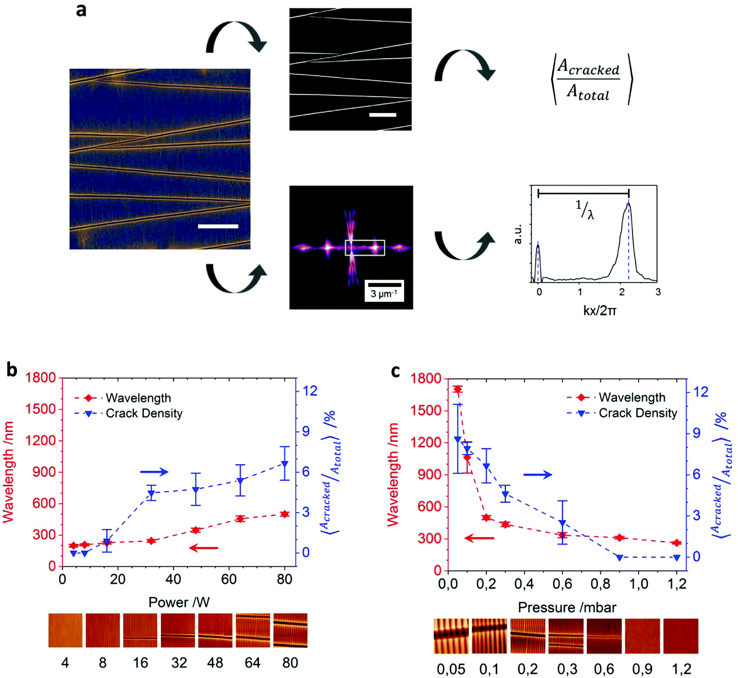 | ||
| Fig. 2 (a) Scheme of data evaluation of wrinkled surfaces: for crack density analysis (top), first a threshold was set for each image, and afterwards the cracked surface area was assessed. Wavelength analysis (bottom) was accomplished via a 2D-Fourier transformation; the scale bar is 20 μm. Results for power (b) and pressure (c) screening, considering crack density and wavelength results; the image size is 10 μm each. | ||
In order to correlate the observed crack densities with the structural properties of the film, we repeat the screenings under the same conditions for un-strained PDMS stripes. These allow for cross-section analysis of the interfacial region via QNM to determine the thickness and mechanical properties of the thin layer at the nanometer scale. The unstrained samples have equal geometries to those in the first part; furthermore they are treated with the same parameters as before. By this we ensure to fabricate compliant layers that are un-cracked and un-wrinkled due to the missing mechanical pre-strain. In a subsequent step we cast a dye-doped embedding consisting of another batch of 1:5 PDMS on top of the oxidized layer, and cut eventually out cross section profiles. The embedding step is necessary, as the analysis will be performed by the contact analysis QNM method. This essentially needs continuous surfaces to measure reliable values. The QNM analysis then is performed crosswise to the thin, oxidized layer, showing a three-layer-system consisting of the post-cast and dye-doped PDMS embedding/thin, plasma-oxidized layer/elastic PDMS substrate (Fig. 3a). The results of both power and pressure screenings are depicted in Fig. 3b and c. Here the elasticity always just represents the maximum stiffness of the layer. It gradually transits from hard to soft, and may be considered as a grouping of innumerable, infinitesimally thin layers with decreasing stiffness. We can identify two regions within the thin, plasma-oxidized layer – on the one hand a steep incline to the maximum Young's modulus, and on the other hand a gentler slope from the modulus’ maximum down to the elasticity value of the elastic bulk material (Fig. 3a). The first region appears due to the overcasting of the oxidized layer with the PDMS embedding. This is due to a gentle thermal curing of the three-layer-system, in order to guarantee a good covalent bonding to the plasma-oxidized layer for the QNM analysis. Therefore the thin oxidized layer also blurs slightly into the embedding, resulting in a broadened layer appearance. Nevertheless, only the second region represents the original plasma-oxidized layer.
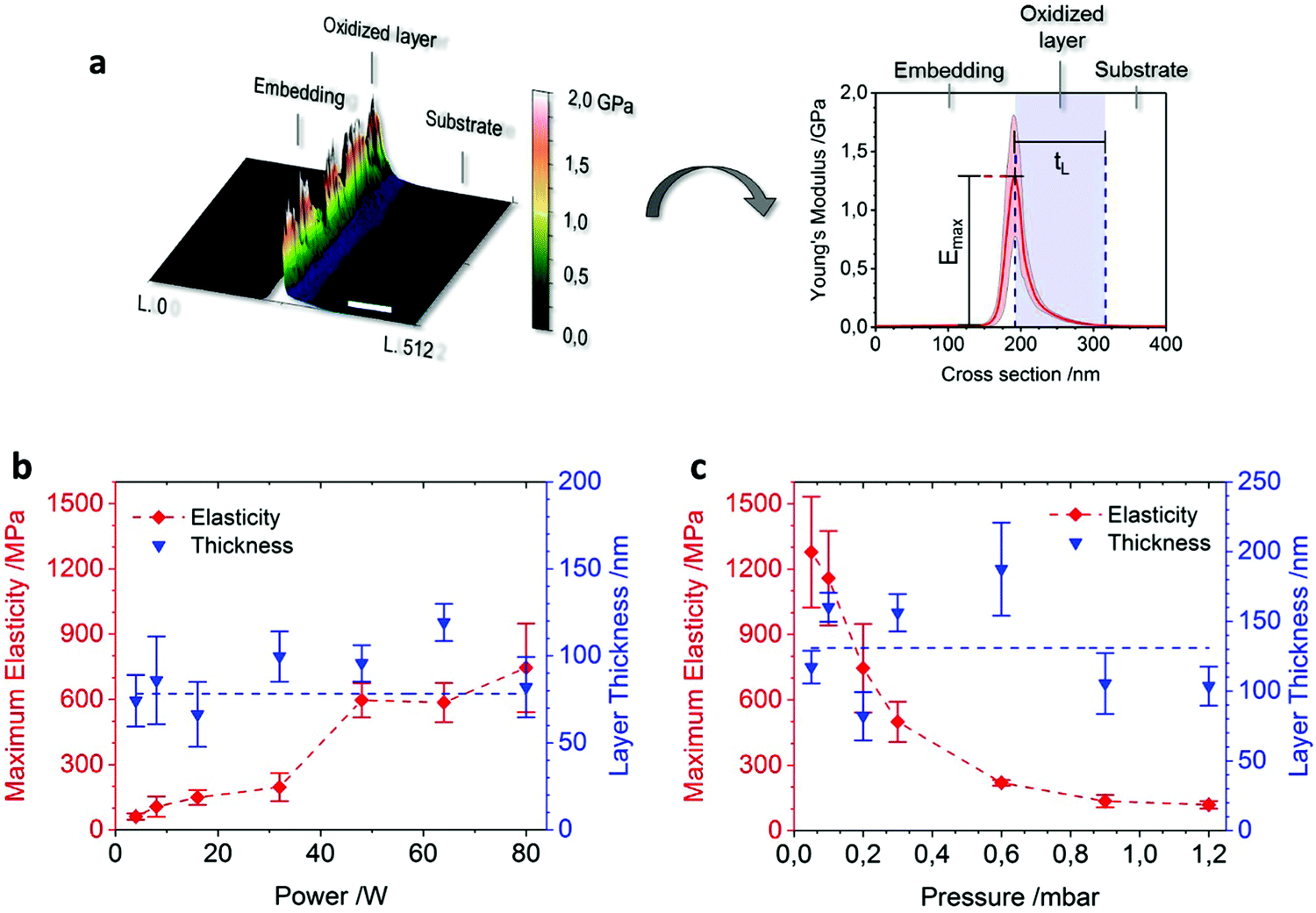 | ||
| Fig. 3 (a) AFM data evaluation: to exemplify the 0.05 mbar-sample from the pressure screening is depicted. First the modulus channel of the QNM measurement is converted to a 3D-data-matrix (left) and eventually averaged line by line over the whole image size of 512 rows (right); the scale bar is 100 nm. Results for power (b) and pressure (c) screening, regarding the maximum elasticity and layer thickness. | ||
We clearly identify an increase in elasticity from the substrate to the layer with decreasing chamber pressure and increasing nominal chamber power. As can be seen in Fig. 3b and c, in the power screening the incline reaches from 61 MPa to 745 MPa (see also Fig. S5, ESI†), and in the pressure screening it is even more pronounced (Fig. S6, ESI†), reaching from 119 MPa to 1278 MPa. This is in good agreement with previously measured screenings for comparable setups.31 Nevertheless, at the same time the thickness of the layer remains relatively constant with values fluctuating around 78 nm for the power screening and 131 nm for the pressure screening (Fig. 3b and c). Within the power screening the deviations from the average layer thickness value are smaller compared to the ones in the pressure screening. The fluctuations can mainly be explained by the difficulty of deciding where the borderline from the PDMS substrate to the elasticity gradient is situated. We set a very low threshold for this crossover in order not to accidently cut the flat parts of the gradient out of the analysis. However, as not all layers show the same ideal gradient characteristics, in those analyses also parts of the PDMS substrate may be counted to the layer's gradient. Yet we see a reliable trend for the layer thickness, which does not rise or drop while changing the power or pressure of the process. The reasons for this nearly constant behavior can be found in the nature of plasma–surface interaction. The modification effect of a polymeric surface upon low pressure plasma treatment is, roughly, a superposition of two major pathways. The first is the impact of energetic ions: depending on the type and energy distribution of ions hitting the surface, a collision cascade with a characteristic range develops. The second is the appearance of Vacuum Ultraviolet (VUV) absorption: the range of VUV photons depends on the wavelength of the plasma emission and the corresponding absorption coefficient of the exposed material. For the given system of plasma, one can assume that the crucial parameters for the interaction range, which are most likely ion energy and VUV wavelength, do not exhibit a pronounced variation across the screening intervals applied in this study.52 So the variability of the excitation range is quite low, and furthermore self-bias effects close to the sample seem to be unlikely due to the very symmetric chamber geometry as well.53 However, the flux of ions and VUV photons should vary significantly as a function of power or pressure. From that point of view the experimental evidence of surface modification with variable degree but constant range appears plausible. The order of magnitude observed for the overall range of the PDMS surface modification suggests that the major contribution arises via the VUV pathway, as bombardment ions penetrate only a few nm into the bulk material.54,55
In order to clarify why the regime of crack-free samples correlates with the gradient nature of the hard layer, we carried out numerical simulations. For technical reasons, the continuous real gradient layers that have been measured are discretized into approximate stepwise gradient layer systems, as depicted in Fig. 4a. Such a multilayered step gradient consists of many small intermediate layers of pre-defined steady thickness (blue curves), whose elasticity values are abstracted from the corresponding real gradient (black curve), while the corresponding Poisson ratio numbers have been estimated from materials with comparable Young's moduli. The Young's modulus of the PDMS substrate was set as E = 3.5 MPa. As a result, the real gradient now can be described via a multilayered step function. Secondly, a theoretical single layer is created, being the arithmetic mean of the experimentally determined Young's modulus along its total layer thickness (red dashed line). It represents the theoretical case, where the oxidized layer has no gradient-shaped interface to the bulk PDMS, and is also the most simple case of a two-layer-system. The three different cases are also described schematically in Fig. S7a (ESI†). We test the real gradients with the cubic model systems of Chan42 and the exponential system of Sui43 (see Fig. S7b, ESI†). We find both in very good agreement with the experimental data, where the exponential system is matching extremely well with a determination coefficient of R2 = 0.996, while the cubic system is only slightly lower at R2 = 0.990. In conclusion, both model systems appear to be suitable for the calculation and prediction of mechanical gradient layers.
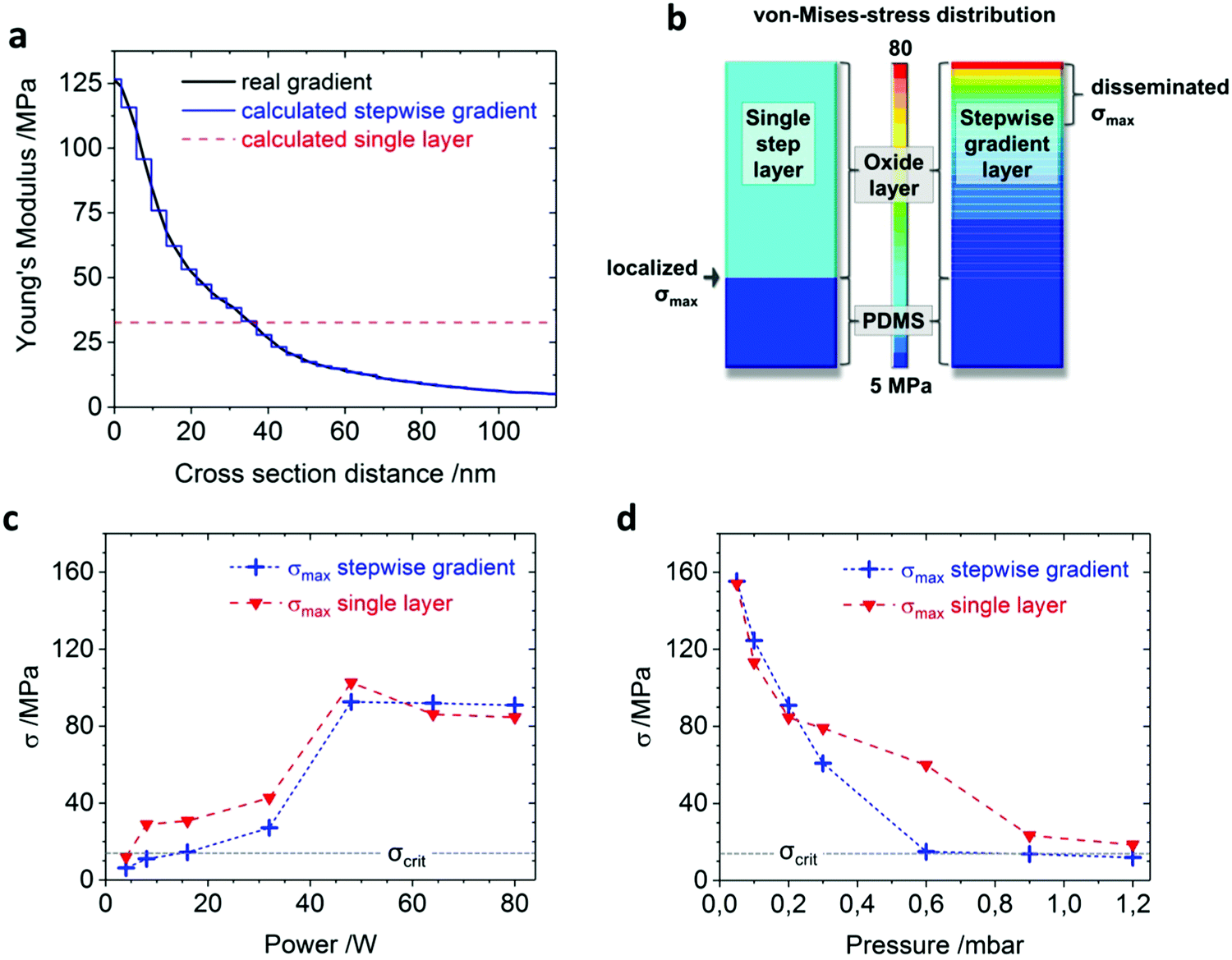 | ||
| Fig. 4 (a) The real gradient (black curve; 1.20 mbar-sample, taken from the pressure screening) is recalculated and overlaid by the stepwise gradient (blue curve) consisting of 30 steps, and eventually compared with the single step layer (red curve), whose stiffness represents the mean value of the real gradient. For the FEM simulation (b), the single layer (left) and also the stepwise gradient (right) are fixed on a quasi-infinite substrate underneath. Both are exposed to a simulated uniaxial strain of ε = 60%, and with equivalent boundary conditions. The results show the von-Mises-stress in both layers graphically, with a maximal stress intensity reaching from 5 to 80 MPa, indicated by the colored scale bar. (c) and (d) represent the simulated von-Mises-stress maxima for each sample, accomplished for the stepwise gradient (blue curve) as well as for the single layer (red curve). The critical stress (black dotted line) is calculated as σcrit = 14 MPa. | ||
For our numerical simulations, both recreated layers are eventually calculated with mechanical ANSYS 19.1 FEM software (Fig. 4b). Boundary conditions are chosen equally for all simulated samples. We define the left sample edge as the foundation, while the strain of ε = 60% is homogeneously applied to the right edge. The mesh size is created automatically, with a medium target range and a densification inside the layer. The results are obtained and displayed in the von-Mises-yield criterion. This allows for the estimation of tensile stress values in the real gradients. By doing so, we obtain two different maximal von-Mises-stress values – one for the stepwise gradient layer and one for the single layer. Plotting them against the according power (Fig. 4c) or pressure (Fig. 4d) values shows a trend similar to the corresponding wavelengths and crack densities in Fig. 2b and c. Nevertheless, besides high power or low pressure values, the stepwise gradient always has a lower σmax compared to its corresponding single layer value. When taking the experimentally derived crack density from Fig. 2b and c into account, we are able to determine a critical tensile stress σcrit, up to which crack-free wrinkling under high mechanical pre-strains is possible. For the power screening, it can be found between 8 and 16 W, and for the pressure screening between 0.6 and 0.9 mbar. From Fig. 4c and d we therefore conclude 13.7 MPa < σmax < 14.4 MPa, so σcrit ∼ 14 MPa. Thus it appears that the maximum stress of each single layer is higher, as the significant drop of elasticity between the hard layer and the soft substrate generates noticeably higher maximal stress values than within the corresponding gradient interface.
Conclusion
We measured the effect of the plasma device power and the plasma chamber pressure on highly strained elastomeric materials, in order to determine the emerging wrinkle wavelengths as well as the crack density. By this we identified a narrow parameter range for each, in which surface cracking does not occur. Based on these findings, we calculated the elasticity for every sample via two approaches: first as a theoretical single layer, and second as a stepwise gradient layer according to the corresponding experimental data. FEM simulations under mechanical strain were executed with both layers, resulting in the implication that the mechanical z-gradients cushioned the maximum tensile stress σmax within the layer-to-substrate-interface. Therefore we could reduce σmax for some parameters below a threshold of σcrit = 14 MPa, where cracking of the surface did not occur. We therefore conclude that the production of crack-free wrinkles can be tuned via the implementation of a mechanical z-gradient in the hard, thin layer. The gradient slope nevertheless must not be too steep, since this leads to internal layer stress values that are higher than a theoretical corresponding single layer setup. For the generation of such gradients with PDMS, we therefore suggest systems that have a high penetration depth, but at the same time can be tuned to low plasma intensities. The insights of this paper can be used to develop crack-free wrinkled surfaces also for other applications, just as for particle assembly, optics, anti-bacterial, anti-cellular or anti-viral surfaces, etc., where disruptive features as cracks may obstruct the nano-structured functionality.Data availability
The raw data can be provided on request.Conflicts of interest
The authors declare no competing financial interest. There are no conflicts to declare.Acknowledgements
We thank Y. Brasse for preliminary work, as well as U. Reuter and A. Janke for assistance in AFM sample preparation. Also we thank L. Zybell for assistance in FEM simulations. This work was funded by the SAB 100333997 BIOS project.References
- L. Dong, X. Quan and P. Cheng, An experimental investigation of enhanced pool boiling heat transfer from surfaces with micro/nano-structures, Int. J. Heat Mass Transfer, 2014, 71, 189–196 CrossRef.
- C. Muratore and A. A. Voevodin, Chameleon Coatings: Adaptive Surfaces to Reduce Friction and Wear in Extreme Environments, Annu. Rev. Mater. Res., 2009, 39(1), 297–324 CrossRef CAS.
- S. Veprek and M. J. G. Veprek-Heijman, Industrial applications of superhard nanocomposite coatings, Surf. Coat. Technol., 2008, 202(21), 5063–5073 CrossRef CAS.
- J. Y. Chung, J. P. Youngblood and C. M. Stafford, Anisotropic wetting on tunable micro-wrinkled surfaces, Soft Matter, 2007, 3(9), 1163–1169 RSC.
- M. J. Madou, Fundamentals of Microfabrication and Nanotechnology – Manufacturing Techniques for Microfabrication and Nanotechnology, CRC Press Publisher, Boca Raton, USA, 2011, p. 2 Search PubMed.
- T. Kaufmann and B. J. Ravoo, Stamps, inks and substrates: polymers in microcontact printing, Polym. Chem., 2010, 1(4), 371–387 RSC.
- J. Bonse, R. Koter, M. Hartelt, D. Spaltmann, S. Pentzien, S. Höhm, A. Rosenfeld and J. Krüger, Femtosecond laser-induced periodic surface structures on steel and titanium alloy for tribological applications, Appl. Phys. A: Mater. Sci. Process., 2014, 117(1), 103–110 CrossRef CAS.
- A. Schweikart and A. Fery, Controlled wrinkling as a novel method for the fabrication of patterned surfaces, Microchim. Acta, 2009, 165(3), 249–263 CrossRef CAS.
- K. Efimenko, M. Rackaitis, E. Manias, A. Vaziri, L. Mahadevan and J. Genzer, Nested self-similar wrinkling patterns in skins, Nat. Mater., 2005, 4, 293 CrossRef CAS PubMed.
- J. Genzer and J. Groenewold, Soft matter with hard skin: from skin wrinkles to templating and material characterization, Soft Matter, 2006, 2(4), 310–323 RSC.
- H. Vandeparre, M. Piñeirua, F. Brau, B. Roman, J. Bico, C. Gay, W. Bao, C. N. Lau, P. M. Reis and P. Damman, Wrinkling Hierarchy in Constrained Thin Sheets from Suspended Graphene to Curtains, Phys. Rev. Lett., 2011, 106(22), 224301 CrossRef.
- Q. Li, X. Han, J. Hou, J. Yin, S. Jiang and C. Lu, Patterning Poly(dimethylsiloxane) Microspheres via Combination of Oxygen Plasma Exposure and Solvent Treatment, J. Phys. Chem. B, 2015, 119(42), 13450–13461 CrossRef CAS.
- J. Thiele, A. R. Abate, H. C. Shum, S. Bachtler, S. Förster and D. A. Weitz, Fabrication of Polymersomes using Double-Emulsion Templates in Glass-Coated Stamped Microfluidic Devices, Small, 2010, 6(16), 1723–1727 CrossRef CAS PubMed.
- D.-Y. Khang, H. Jiang, Y. Huang and J. A. Rogers, A Stretchable Form of Single-Crystal Silicon for High-Performance Electronics on Rubber Substrates, Science, 2006, 311(5758), 208–212 CrossRef CAS.
- E. P. Chan and A. J. Crosby, Fabricating Microlens Arrays by Surface Wrinkling, Adv. Mater., 2006, 18(24), 3238–3242 CrossRef CAS.
- M. Tebbe, M. Mayer, B. A. Glatz, C. Hanske, P. T. Probst, M. B. Müller, M. Karg, M. Chanana, T. A. F. König, C. Kuttner and A. Fery, Optically anisotropic substrates via wrinkle-assisted convective assembly of gold nanorods on macroscopic areas, Faraday Discuss., 2015, 181, 243–260 RSC.
- P. T. Probst, S. Sekar, T. A. F. König, P. Formanek, G. Decher, A. Fery and M. Pauly, Highly Oriented Nanowire Thin Films with Anisotropic Optical Properties Driven by the Simultaneous Influence of Surface Templating and Shear Forces, ACS Appl. Mater. Interfaces, 2018, 10(3), 3046–3057 CrossRef CAS.
- B. A. Glatz, M. Tebbe, B. Kaoui, R. Aichele, C. Kuttner, A. E. Schedl, H.-W. Schmidt, W. Zimmermann and A. Fery, Hierarchical line-defect patterns in wrinkled surfaces, Soft Matter, 2015, 11(17), 3332–3339 RSC.
- G. Miquelard-Garnier, A. B. Croll, C. S. Davis and A. J. Crosby, Contact-line mechanics for pattern control, Soft Matter, 2010, 6(22), 5789–5794 RSC.
- H. Vandeparre, S. Gabriele, F. Brau, C. Gay, K. K. Parker and P. Damman, Hierarchical wrinkling patterns, Soft Matter, 2010, 6(22), 5751–5756 RSC.
- Y. Ni, D. Yang and L. He, Spontaneous wrinkle branching by gradient stiffness, Phys. Rev. E: Stat., Nonlinear, Soft Matter Phys., 2012, 86(3), 031604 CrossRef.
- S. Yu, Y. Ni, L. He and Q.-L. Ye, Tunable Formation of Ordered Wrinkles in Metal Films with Controlled Thickness Gradients Deposited on Soft Elastic Substrates, ACS Appl. Mater. Interfaces, 2015, 7(9), 5160–5167 CrossRef CAS.
- B. Kaoui, A. Guckenberger, A. Krekhov, F. Ziebert and W. Zimmermann, Coexistence of stable branched patterns in anisotropic inhomogeneous systems, New J. Phys., 2015, 17(10), 103015 CrossRef.
- Y. Xuan, X. Guo, Y. Cui, C. Yuan, H. Ge, B. Cui and Y. Chen, Crack-free controlled wrinkling of a bilayer film with a gradient interface, Soft Matter, 2012, 8(37), 9603–9609 RSC.
- S. K. Park, Y.-J. Kwark, S. Nam, S. Park, B. Park, S. Yun, J. Moon, J.-I. Lee, B. Yu and K.-U. Kyung, Wrinkle structures formed by formulating UV-crosslinkable liquid prepolymers, Polymer, 2016, 99, 447–452 CrossRef CAS.
- D. Chandra and A. J. Crosby, Self-Wrinkling of UV-Cured Polymer Films, Adv. Mater., 2011, 23(30), 3441–3445 CrossRef CAS PubMed.
- J. M. Torres, C. M. Stafford and B. D. Vogt, Photoinitator surface segregation induced instabilities from polymerization of a liquid coating on a rigid substrate, Soft Matter, 2012, 8(19), 5225–5232 RSC.
- S. J. Ma, S. J. Mannino, N. J. Wagner and C. J. Kloxin, Photodirected Formation and Control of Wrinkles on a Thiol–ene Elastomer, ACS Macro Lett., 2013, 2(6), 474–477 CrossRef CAS.
- S. K. Park, Y.-J. Kwark, J. Moon, C. W. Joo, B. G. Yu and J.-I. Lee, Finely Formed, Kinetically Modulated Wrinkle Structures in UV-Crosslinkable Liquid Prepolymers, Macromol. Rapid Commun., 2015, 36(22), 2019 CrossRef CAS PubMed.
- M. Watanabe and K. Mizukami, Well-Ordered Wrinkling Patterns on Chemically Oxidized Poly(dimethylsiloxane) Surfaces, Macromolecules, 2012, 45(17), 7128–7134 CrossRef CAS.
- S. Béfahy, P. Lipnik, T. Pardoen, C. Nascimento, B. Patris, P. Bertrand and S. Yunus, Thickness and Elastic Modulus of Plasma Treated PDMS Silica-like Surface Layer, Langmuir, 2010, 26(5), 3372–3375 CrossRef PubMed.
- D. Rhee, W.-K. Lee and T. W. Odom, Crack-Free, Soft Wrinkles Enable Switchable Anisotropic Wetting, Angew. Chem., Int. Ed., 2017, 56(23), 6523–6527 CrossRef CAS PubMed.
- Z. Li, S. Zhang, P. Zhang, D. Yang, G. Jin and H. Ma, Surface initiated polymerization from integrated poly(dimethylsiloxane) enables crack-free large area wrinkle formation, Polym. Adv. Technol., 2012, 23(9), 1240–1245 CrossRef CAS.
- K. Efimenko, W. E. Wallace and J. Genzer, Surface Modification of Sylgard-184 Poly(dimethyl siloxane) Networks by Ultraviolet and Ultraviolet/Ozone Treatment, J. Colloid Interface Sci., 2002, 254(2), 306–315 CrossRef CAS.
- H. Hillborg, J. F. Ankner, U. W. Gedde, G. D. Smith, H. K. Yasuda and K. Wikström, Crosslinked polydimethylsiloxane exposed to oxygen plasma studied by neutron reflectometry and other surface specific techniques, Polymer, 2000, 41(18), 6851–6863 CrossRef CAS.
- M. Ouyang, C. Yuan, R. J. Muisener, A. Boulares and J. T. Koberstein, Conversion of Some Siloxane Polymers to Silicon Oxide by UV/Ozone Photochemical Processes, Chem. Mater., 2000, 12(6), 1591–1596 CrossRef CAS.
- A. E. Özçam, K. Efimenko and J. Genzer, Effect of ultraviolet/ozone treatment on the surface and bulk properties of poly(dimethyl siloxane) and poly(vinylmethyl siloxane) networks, Polymer, 2014, 55(14), 3107–3119 CrossRef.
- F. A. Bayley, J. L. Liao, P. N. Stavrinou, A. Chiche and J. T. Cabral, Wavefront kinetics of plasma oxidation of polydimethylsiloxane: limits for sub-μm wrinkling, Soft Matter, 2014, 10(8), 1155–1166 RSC.
- D. B. H. Chua, H. T. Ng and S. F. Y. Li, Spontaneous formation of complex and ordered structures on oxygen-plasma-treated elastomeric polydimethylsiloxane, Appl. Phys. Lett., 2000, 76(6), 721–723 CrossRef CAS.
- H. Ye, Z. Gu and D. H. Gracias, Kinetics of Ultraviolet and Plasma Surface Modification of Poly(dimethylsiloxane) Probed by Sum Frequency Vibrational Spectroscopy, Langmuir, 2006, 22(4), 1863–1868 CrossRef CAS.
- J.-Y. Park, H. Y. Chae, C.-H. Chung, S. J. Sim, J. Park, H. H. Lee and P. J. Yoo, Controlled wavelength reduction in surface wrinkling of poly(dimethylsiloxane), Soft Matter, 2010, 6(3), 677–684 RSC.
- E. P. Chan and A. J. Crosby, Spontaneous formation of stable aligned wrinkling patterns, Soft Matter, 2006, 2(4), 324–328 RSC.
- J. Sui, J. Chen, X. Zhang, G. Nie and T. Zhang, Symplectic Analysis of Wrinkles in Elastic Layers With Graded Stiffnesses, J. Appl. Mech., 2018, 86(1), 011008 CrossRef.
- M. Mayer, M. Tebbe, C. Kuttner, M. J. Schnepf, T. A. F. König and A. Fery, Template-assisted colloidal self-assembly of macroscopic magnetic metasurfaces, Faraday Discuss., 2016, 191, 159–176 RSC.
- J. B. Kim, P. Kim, N. C. Pégard, S. J. Oh, C. R. Kagan, J. W. Fleischer, H. A. Stone and Y.-L. Loo, Wrinkles and deep folds as photonic structures in photovoltaics, Nat. Photonics, 2012, 6, 327 CrossRef CAS.
- K. Efimenko, J. Finlay, M. E. Callow, J. A. Callow and J. Genzer, Development and Testing of Hierarchically Wrinkled Coatings for Marine Antifouling, ACS Appl. Mater. Interfaces, 2009, 1(5), 1031–1040 CrossRef CAS.
- M. Palacios-Cuesta, A. Cortajarena, O. García and J. Rodríguez-Hernández, Fabrication of Functional Wrinkled Interfaces from Polymer Blends: Role of the Surface Functionality on the Bacterial Adhesion, Polymers, 2014, 6(11), 2845 CrossRef.
- M. Guvendiren and J. A. Burdick, The control of stem cell morphology and differentiation by hydrogel surface wrinkles, Biomaterials, 2010, 31(25), 6511–6518 CrossRef CAS.
- J. L. Beuth, Cracking of thin bonded films in residual tension, Int. J. Solids Struct., 1992, 29(13), 1657–1675 CrossRef.
- J. W. Hutchinson and Z. Suo, Advances in Applied Mechanics – Mixed Mode Cracking in Layered Materials, Elsevier, 1991, pp. 63–191 Search PubMed.
- R. S. O’Connor, X. Hao, K. Shen, K. Bashour, T. Akimova, W. W. Hancock, L. C. Kam and M. C. Milone, Substrate Rigidity Regulates Human T Cell Activation and Proliferation, J. Immunol., 2012, 189(3), 1330–1339 CrossRef.
- M. R. Wertheimer, A. C. Fozza and A. Holländer, Industrial processing of polymers by low-pressure plasmas: the role of VUV radiation, Nucl. Instrum. Methods Phys. Res., Sect. B, 1999, 151(1), 65–75 CrossRef CAS.
- D. Pasquariello, M. Lindeberg, C. Hedlund and K. Hjort, Surface energy as a function of self-bias voltage in oxygen plasma wafer bonding, Sens. Actuators, A, 2000, 82(1), 239–244 CrossRef CAS.
- V. A. Godyak, R. B. Piejak and B. M. Alexandrovich, Measurement of electron energy distribution in low-pressure RF discharges, Plasma Sources Sci. Technol., 1992, 1(1), 36 CrossRef CAS.
- V. A. Godyak, R. B. Piejak and B. M. Alexandrovich, Electron energy distribution function measurements and plasma parameters in inductively coupled argon plasma, Plasma Sources Sci. Technol., 2002, 11(4), 525 CrossRef CAS.
Footnote |
| † Electronic supplementary information (ESI) available. See DOI: 10.1039/c8sm01910j |
| This journal is © The Royal Society of Chemistry 2019 |