
High capacity, power density and cycling stability of silicon Li-ion battery anodes with a few layer black phosphorus additive†
Kingshuk
Roy‡
ab,
Malik
Wahid‡
c,
Dhanya
Puthusseri‡
b,
Apurva
Patrike
a,
Subas
Muduli
 *a,
Ramanathan
Vaidhyanathan
*b and
Satishchandra
Ogale
*a
*a,
Ramanathan
Vaidhyanathan
*b and
Satishchandra
Ogale
*a
aDepartment of Physics, Centre for Energy Science, Indian Institute of Science Education and Research Pune, Pune 411008, India. E-mail: satishogale@iiserpune.ac.in; subashmuduli@gmail.com
bDepartment of Chemistry, Centre for Energy Science, Indian Institute of Science Education and Research Pune, Pune 411008, India. E-mail: vaidhya@iiserpune.ac.in
cDepartment of Chemistry, National Institute of Technology, Srinagar-190006, India
First published on 16th October 2018
Abstract
The exceptionally high theoretical capacity of silicon as a Li-ion battery anode material (4200 mA h g−1) is hard to realize and stabilize in practice due to its huge (300%) volume changes during lithiation/de-lithiation. The design, constitution, and microstructure of the anode hold the key to a desired potential solution. Towards this end, herein we exploit the very high flexibility of few layer black phosphorus (FLBP), far exceeding that of most of the carbon forms extensively studied thus far, attributed to its typical puckered structure and low Young's modulus, to realize an exceptionally high capacity, power density and stability Si nanoparticle based anode design. Our process employs a simple physical mixture of silicon nanoparticles (SiNPs) and chemically exfoliated few layer black phosphorus (FLBP), which is simple and easily scalable. Very high capacity values reaching 3386 mA h g−1 and 2331 mA h g−1 at current densities of 0.1 A g−1 and 0.5 A g−1, respectively, are obtained with impressive stability measured up to 250 cycles.
The modern electrically driven world largely depends on the availability of efficient and robust energy storage devices, both stationary and transportable. Li-ion batteries are still the highest performing commercialized rechargeable batteries, wherein graphite is used as the anode due to its high stability, very low irreversible capacity loss, and low cost. However, its theoretical capacity being low (372 mA h g−1, LiC6) alternate high capacity anode materials are being sought as its potential replacements. In particular, these include alloying materials such as Sn (theoretical capacity 992 mA h g−1, Li4.4Sn) and Si (theoretical capacity 4200 mA h g−1, Li22Si5).1–3 In spite of its very high theoretical capacity, utilization of silicon as an anode has been plagued by stability issues emanating from the huge (300%) volume expansion and contraction upon lithiation and de-lithiation, which causes mechanical rupturing and loss of electrical contact between the particles.4–6 Along with the volume expansion, there are a number of other issues with Si anodes such as poor material conductivity, repeated chemical reaction with the electrolyte, high irreversible capacity loss, and fast capacity fade.7 Therefore, a number of very interesting and innovative strategies have been designed and employed in recent years to stabilize the high capacity of Si, the primary ones being the use of carbon materials as elastic conducting additives in the form of composites or coatings, as discussed at length in multiple significant contributions by Y. Cui and coworkers, Y. Sun and coworkers, and many others.3–6,8–16 In some cases, these strategies are synthetically quite complex, while in other cases the use of a larger weight fraction of carbon concedes the high capacity advantage of silicon, because carbon in itself is an ineffective material (capacity 300–400 mA h g−1) in the capacity context.8–10,15,16
Non-carbon conductive alternatives which could either be effective in minute quantities in accommodating the stresses and/or could concurrently contribute through their own high Li ion storage capacity have also been researched, and innovative strategies based on the use of Si–X compounds like SiO2, SiO, CaSi2, Mg2Si etc. have shown good promise in this regard.17–21 Several research groups have tried to stabilize the Si anode by optimizing the binders as well. Poly(vinylidene fluoride) (PVDF), being the most widely used binder for Li ion battery electrode preparation owing to its fair thermal and electrochemical stability, is not so popular in the context of Si anodes since its elasticity is less.22,23 Thus, capacity fade results even after 8–10 charge discharge cycles due to the formation of a protective solid electrolyte interphase (SEI) layer in the subsequent cycles.24 Hence several research groups have come up with different binders such as styrene butadiene rubber (SBR) and sodium carboxymethyl cellulose (CMC) and cross-linked polymer binders such as poly(acrylic acid) (PAA)–CMC composites where large numbers of –OH and –COOH groups provide very strong and stable covalent bonding and/or hydrogen bonding interaction with oxide layers grown on the Si nanoparticles, thus giving stability to the electrode and preventing it from undergoing further pulverization.25–30
Herein we examine chemically exfoliated few layer black phosphorus (FLBP) as an extremely large stress absorbing material with very low Young's modulus (superior to most carbon forms studied thus far), and as a simple physical additive, providing a Si nanoparticle based anode with very high capacity, power density and stability. Importantly, we have used the conventional and most widely used PVDF binder without resorting to special binders containing highly oxygen containing groups or cross-linking polymers.
It has been theoretically shown that FLBP, a material of immense current interest due to its several unique properties, can sustain huge strains up to 32% in view of its unique puckered structure which can flatten in response to strain without the need to extend the P–P bond,31–34 a property flat graphene is not endowed with. The attendant much smaller Young's modulus of FLBP thus brings great value to strain engineering in the case of the Si-anode problem. Thus, by deviating considerably from the mainstream strategies like the Si–C anode strategy for Li-ion anodes or synthesis of binary or ternary Si compounds that involve rigorous synthesis protocols, we have achieved a SiNP based anode that not only delivers the desirable exceptionally high reversible capacity of 3386 mA h g−1 but also excellent rate-cum-cycling stability. This is realized by using FLBP as a simple and optimum physical additive. Note that this and other values reported here are calculated with the total weight of the material and not simply the weight of Si. Thus, capacity values of 2331 mA h g−1, 1901 mA h g−1, 1617 mA h g−1, and 1207 mA h g−1 are realized at current densities of 0.5 A g−1, 1 A g−1, 2 A g−1, and 4 A g−1, respectively, which are among the highest reported for Si (please see Table SI-1†).
We would like to emphasize that physical addition of phosphorene or few layer BP (FLBP) to a silicon nanoparticle-based anode adopted in our work is a novel approach compared to using any form of phosphorus for silicon-based compound synthesis and using that compound as an anode. This is because in our case the mechanically flexible identity of FLBP is maintained intact, which is of utmost importance for the absorption of stresses.
There is only one previous report by Bo et al. wherein phosphorene was used to encapsulate Si to improve the performance of the Si anode.36 However, unlike our work using the most commonly and widely used PVDF binder, they have used a sodium carboxymethyl cellulose (NaCMC) binder which is known to stabilize SiNP based anodes even without addition of any external additives.37,38 Also, they have shown stability data only up to 100 cycles without providing any rate performance data.
As an example of another compound formation strategy one could cite a recent interesting work of Park et al. who synthesized a silicon di-phosphide (SiP2) compound having a 3D crystalline framework with a 6-fold coordination of Si, in which the Li-ion storage mechanism involves a three-step reaction between SiP2 and Li.35 Moreover, the authors also included carbon in the composite anode through high energy ball milling of SiP2 and C (super P) in a weight ratio of 60![[thin space (1/6-em)]](https://www.rsc.org/images/entities/char_2009.gif) :40 and achieved a good reversible capacity of 1661 mA h g−1 though with poor cycling stability (only 50% retention after 100 cycles) when operated in a potential window of 0–2 V. Moving into a revised potential window of 0.25–2 V they could achieve enhanced cycling stability, though with a lower reversible capacity of 1137 mA h g−1. Clearly, as indicated above, our strategy has provided far superior results, and without any carbon additive.
:40 and achieved a good reversible capacity of 1661 mA h g−1 though with poor cycling stability (only 50% retention after 100 cycles) when operated in a potential window of 0–2 V. Moving into a revised potential window of 0.25–2 V they could achieve enhanced cycling stability, though with a lower reversible capacity of 1137 mA h g−1. Clearly, as indicated above, our strategy has provided far superior results, and without any carbon additive.
Field emission scanning electron microscopy (FESEM) and high resolution transmission electron microscopy (HRTEM) data, and the Raman spectra for FLBP are provided in the ESI (Fig. S1†). The FESEM images and XRD data for SiNPs are shown in Fig. S2.† These data confirm the essential expected structural and morphological features pertaining to the two separate systems used in this work.
The detailed SiNPs/FLBP electrode fabrication procedure employed in our work is given in the electrode fabrication section in the ESI.† Different relative compositions of SiNPs and FLBP were carefully studied (please see Table SI-2†). The optimized 92:8 weight ratio (8 wt% FLBP) yielded the best performance. Fig. 1a displays a cartoon depicting the expected physical union of SiNPs and FLBP in the electrode. The uniform distribution of inter-dispersed FLBP in the continuum of SiNPs can be clearly seen from Fig. 1b. The comparison of the morphology in the case of only SiNP and SiNP–FLBP composite electrode is shown in Fig. S3.† The weight ratio observed from the EDAX analysis (Fig. 1c) for the optimal case is in good agreement with the weight ratios added during electrode fabrication. The X-ray diffraction (XRD) pattern shown in Fig. 1d reveals that the physical individuality of constituents is maintained in the electrode, as expected.
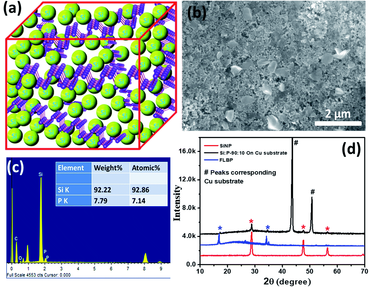 | ||
| Fig. 1 (a) Schematic depicting the union of FLBP and SiNPs in the electrode; (b) FE-SEM image of the SiNP–FLBP composite electrode; (c) EDAX data showing a composition of SiNP:FLBP (92:8); (d) X-ray diffraction data of SiNP, FLBP and SiNP–FLBP composite (on a Cu foil electrode). | ||
The rate-cum-stability plots shown in Fig. 2a with other electrochemical measurements such as cyclic voltammetry (Fig. 2c) and charge discharge plots of SiNPs and the SiNP–FLBP composite (Fig. 2b and d) reveal a highly impressive near theoretical electrochemical performance provided by our FLBP-based SiNP LiB anode design. A comparison of the cyclic voltammetry data of SiNPs and the SiNP–FLBP composite system can be found in the ESI (Fig. S4†). The first reversible capacity achieved in the SiNPs/FLBP-92:8 mixed anode (3384 mA h g−1) is clearly superior to the separate SiNPs (3003 mA h g−1) and FLBP (143 mA h g−1) anodes. The expected capacity based on the observed (and not theoretical) individual performances of SiNPs and FLBP amounts to 2717 mA h g−1 which implies a significant enhancement of 669 mA h g−1. This enhancement in FLBP/SiNPs may be accounted for by considering the improvement in the effective capacity delivered by the SiNPs when inter-dispersed by FLBP in the electrode. It can be noted from the inset of Fig. 2b and S5a and b† that the electrochemical contribution of FLBP is really negligible in terms of capacity, and it is only working as a stress-absorbing cushion by protecting SiNPs from pulverization under repeated lithiation–delithiation cycles.
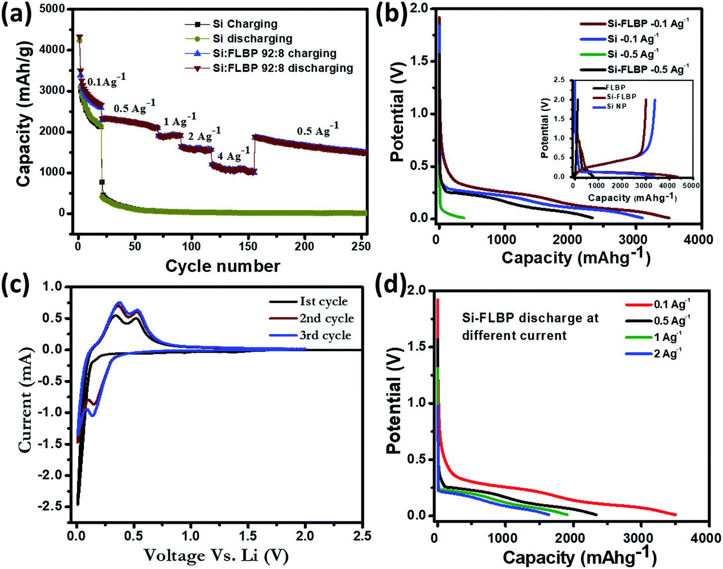 | ||
| Fig. 2 (a) Rate cum stability plot for SiNP and SiNP–FLBP composite electrodes, (b) comparison of charge discharge plots for SiNPs and SiNP–FLBP composite 0.1 A g−1 and 0.5 A g−1, (c) cyclic voltammetry data of the SiNP–FLBP composite system and (d) charge discharge data for the SiNP–FLBP composite system at 0.1 A g−1, 0.5 A g−1, 1 A g−1 and 2 A g−1. | ||
From Fig. 2a dramatic differences may be noted in the rate-cum-stability characteristics of the SiNP and FLBP/SiNP anodes. At low current density of 0.1 A g−1, after 20 cycles the SiNP electrode shows 72% retention, while the SiNPs/FLBP-92:8 electrode shows 79% retention. The curves bifurcate significantly as the current density is increased. Indeed, the remarkable result realized in this work is the high capacity retention at higher current densities as revealed by Fig. 2a. While the capacity of only SiNPs-based anode declines by an order of magnitude to a value of only 392 mA h g−1 at higher current density of 0.5 A g−1, the SiNPs/FLBP-92:8 displays commendable retention with a capacity of 2331 mA h g−1 even at this current density (Fig. 2b), a huge difference indeed.
The stability comparison over the next 50 cycles at a higher current density of 0.5 A g−1 further establishes the superiority of the SiNPs/FLBP-92:8 anode. While the only SiNP anode deteriorates by a drastic decline to the value of only 58 mA h g−1 from the initial 393 mA h g−1 at the end of the 50th cycle, the SiNPs/FLBP-92:8 anode displays tremendous integrity with a very high capacity value of 2120 mA h g−1 at the end of the 50th cycle. The increase in the current density to 1 A g−1 provides an equally impressive value of 1907 mA h g−1, which runs quite smoothly for the next 20 cycles. The capacities of 1636 mA h g−1 and 1207 mA h g−1 are realized at the current densities of 2 A g−1 and 4 A g−1, respectively. When again brought back to 0.5 A g−1, a high capacity of 1866 mA h g−1 is still realized (effectively implying 83% retention after 150 cycles performed at different high currents) and the anode ran smoothly at this current for the next 20 cycles.
We would further like to point out that we achieved a high first cycle coulombic efficiency of 78% which is quite comparable with other reports. This in-turn implies that in our case there is no huge irreversible capacity loss in the first cycle, which is a commonly encountered problem with Si-based anodes. Only a few reports have shown higher first cycle coulombic efficiency, but with a high amount of carbon used as an additive. Separately, our cell also showed promising performance in terms of very slow capacity fading and long term cycling stability (65% retention of capacity after 250 cycles). A comparison of the electrochemical performance of SiNPs–FLBP with other recent reports on Si or Si/C composites as anodes for Li-ion batteries is presented in Table SI-1 in the ESI.†
To confirm the mechanical stability of the SiNP–FLBP electrode in comparison with the only SiNP-based electrode under lithiation/de-lithiation, the morphologies of both these electrodes were examined after several charge discharge cycles. The FESEM images of Fig. 3a and b reveal that the SiNP electrode forms multiple huge cracks after 20 cycles, while our SiNP–FLBP electrode does not show any discernible cracks even after 250 cycles. Even at higher magnification, the cracks are visible for the SiNP case whereas no cracks are visible for the SiNP–FLBP case (Fig. S6†). The cross-sectional SEM images show that after 250 charge–discharge cycles FLBP remains intact protecting the SiNPs from pulverization and rupture (Fig. S7†).
 | ||
| Fig. 3 (a and b) Morphology revealed by FE-SEM of the (a) SiNP-based anode after 20 charge discharge cycles, and (b) SiNP–FLBP anode after 250 charge discharge cycles. (c) Schematic bringing out the primary benefit of using the FLBP additive to the SiNP anode. | ||
We can attribute the excellent performance observed in our case to the stress-absorbing cushion provided by FLBP to silicon due to its exceptional flexibility (very low Young's modulus) emanating from the unique puckered crystal structure. Equally importantly, for the SiNP–FLBP anode the SEI layer is also noted to be very stable; and even after long cycling the electrode is covered with a uniform SEI without cracks. This helps the SiNPs maintain the inter-particle electrical contact with conductivity assistance of FLBP leading to very high and stable capacity. A schematic representing the above scenario is presented in Fig. 3c.
In order to probe the lithiation/de-lithiation reaction dynamics in the two cases we carried out impedance analysis at different bias voltages over the frequency range from 100 mHz to 300 kHz, and AC amplitude of 10 mV. The choice of bias voltage was primarily made on the basis of the working potentials. The basic idea was to excite the cell with an AC impulse at potentials close to the working potentials and record the system response through impedance spectroscopy. The Nyquist plots for SiNP and SiNP–FLBP anodes at different bias voltages are compared in Fig. 4. The RCT (charge transfer resistance) values for SiNP and SiNP/FLBP anodes were obtained for the bias voltages of 0 V, 0.1 V, 0.2 V, 0.3 V and 0.5 V from the respective semicircular curves in Fig. 4. The comparison of RCT values suggests that lithiation/delithiation in SiNPs–FLBP is more facile at higher voltages compared to lower voltages (in total contrast to the only SiNP case). This can be correlated with the electrochemical signatures observed from their charge discharge profiles, where it is clearly seen that the working potential of the SiNP–FLBP composite is higher as compared to only SiNPs. The arrow in Fig. 4 shows the dramatic difference of RCT behavior for the SiNP and SiNP–FLBP cases when the bias voltage has been changed to 0.2 volt from 0.1 volt. The inset of Fig. 4 shows the change of RCT for the SiNP–FLBP case by changing the potential from 0 V to 0.5 V. This observation also suggests that FLBP has a definite electrochemical influence on the lithiation/de-lithiation dynamics in addition to providing a flexible, strain absorbing, and electrically conducting cushion. The electrochemical influence may be due to a different type of lithiation mechanism operative in the composite case (2D material support system) compared to the bare nanoparticle case, since FLBP itself does not contribute much to the capacity.39 The ESI provides a comparison of RCT for different bias voltages for SiNP and SiNP–FLBP cases (Fig. S8†).
 | ||
| Fig. 4 Nyquist plots for electrochemical impedance measurements for SiNP and SiNP–FLBP composite systems at different applied bias voltages. 0 volt stands for no applied bias. The inset shows the change of charge transfer resistance (RCT) of the SiNP–FLBP composite on increasing the bias voltages from 0 volt to 0.5 volt. | ||
Conclusions
In conclusion, we have demonstrated the design of a SiNP based anode for Li-ion batteries with an optimal small quantity of FLBP physical additive which has provided very impressive capacity and stability. This is a departure from the commonly used approach employing different forms of functional carbons as additives or partner materials in Si–C composites. Our approach harnesses the uniquely flexible lithiation/delithiation stress absorbing character of FLBP that is far superior to most carbon forms. Thus very high capacity values reaching 3386 mA h g−1 and 2331 mA h g−1 at current densities of 0.1 A g−1 and 0.5 A g−1, respectively, are obtained with impressive stability measured up to 250 cycles. We believe that this work will open new avenues for possible utilization of other novel 2D materials in the alkali ion battery context.Conflicts of interest
There are no conflicts to declare.Acknowledgements
K. R. would like to thank IISER Pune for fellowship, and the authors would like to thank DST CERI, DST Nanomission (Thematic unit program) and Indo-UK SUNRISE program for funding support. D. P. would like to thank DST-SERB for funding.Notes and references
- J. B. Goodenough and K. S. Park, J. Am. Chem. Soc., 2013, 135, 1167–1176 CrossRef CAS PubMed.
- W. M. Zhang, J. S. Hu, Y. G. Guo, S. F. Zheng, L. S. Zhong, W. G. Song and L. J. Wan, Adv. Mater., 2008, 20, 1160–1165 CrossRef CAS.
- S. Suresh, Z. P. Wu, S. F. Bartolucci, S. Basu, R. Mukherjee, T. Gupta, P. Hundekar, Y. Shi, T. M. Lu and N. Koratkar, ACS Nano, 2017, 11, 5051–5061 CrossRef CAS PubMed.
- X. Su, Q. Wu, J. Li, X. Xiao, A. Lott, W. Lu, B. W. Sheldon and J. Wu, Adv. Energy Mater., 2014, 4, 1300882 CrossRef.
- C. Chae, H. J. Noh, J. K. Lee, B. Scrosati and Y. K. Sun, Adv. Funct. Mater., 2014, 24, 3036–3042 CrossRef CAS.
- Z. Lu, N. Liu, H. W. Lee, J. Zhao, W. Li, Y. Li and Y. Cui, ACS Nano, 2015, 9, 2540–2547 CrossRef CAS PubMed.
- X. Zuo, J. Zhu, P. Müller-Buschbaum and Y. J. Cheng, Nano Energy, 2017, 31, 113–143 CrossRef CAS.
- S. Fang, L. Shen, Z. Tong, H. Zheng, F. Zhang and X. Zhang, Nanoscale, 2015, 7, 7409–7414 RSC.
- H. Wu, G. Zheng, N. Liu, T. J. Carney, Y. Yang and Y. Cui, Nano Lett., 2012, 12, 904–909 CrossRef CAS PubMed.
- B. Wang, X. Li, X. Zhang, B. Luo, M. Jin, M. Liang, S. A. Dayeh, S. T. Picraux and L. Zhi, ACS Nano, 2013, 7, 1437–1445 CrossRef CAS PubMed.
- M. J. Choi, Y. Xiao, J. Y. Hwang, I. Belharouak and Y. K. Sun, J. Power Sources, 2017, 348, 302–310 CrossRef CAS.
- J. K. Lee, C. Oh, N. Kim, J. Y. Hwang and Y. K. Sun, J. Mater. Chem. A, 2016, 4, 5366–5384 RSC.
- M. G. Jeong, H. L. Du, M. Islam, J. K. Lee, Y. K. Sun and H. G. Jung, Nano Lett., 2017, 17, 5600–5606 CrossRef CAS PubMed.
- Y. Li, K. Yan, H.-W. Lee, Z. Lu, N. Liu and Y. Cui, Nat. Energy, 2016, 1, 15029 CrossRef CAS.
- Q. Xu, J. Y. Li, J. K. Sun, Y. X. Yin, L. J. Wan and Y. G. Guo, Adv. Energy Mater., 2017, 7, 1–6 Search PubMed.
- Z. Luo, Q. Xiao, G. Lei, Z. Li and C. Tang, Carbon, 2016, 98, 373–380 CrossRef CAS.
- G. A. Roberts, E. J. Cairns and J. A. Reimer, J. Electrochem. Soc., 2004, 151, A493 CrossRef CAS.
- H. Kim, J. Choi, H.-J. Sohn and T. Kang, J. Electrochem. Soc., 1999, 146, 4401–4405 CrossRef CAS.
- J. Wolfenstine, J. Power Sources, 2003, 124, 241–245 CrossRef CAS.
- C. M. Park, W. Choi, Y. Hwa, J. H. Kim, G. Jeong and H. J. Sohn, J. Mater. Chem., 2010, 20, 4854–4860 RSC.
- M. Yamada, A. Ueda, K. Matsumoto and T. Ohzuku, J. Electrochem. Soc., 2011, 158, A417 CrossRef CAS.
- J. Li, R. B. Lewis and J. R. Dahn, Electrochem. Solid-State Lett., 2007, 10, A17 CrossRef CAS.
- H. Buqa, M. Holzapfel, F. Krumeich, C. Veit and P. Novák, J. Power Sources, 2006, 161, 617–622 CrossRef CAS.
- W.-R. Liu, M.-H. Yang, H.-C. Wu, S. M. Chiao and N.-L. Wu, Electrochem. Solid-State Lett., 2005, 8, A100 CrossRef CAS.
- A. Magasinski, B. Zdyrko, I. Kovalenko, B. Hertzberg, R. Burtovyy, C. F. Huebner, T. F. Fuller, I. Luzinov and G. Yushin, ACS Appl. Mater. Interfaces, 2010, 2, 3004–3010 CrossRef CAS PubMed.
- D. Munao, J. W. M. Van Erven, M. Valvo, E. Garcia-Tamayo and E. M. Kelder, J. Power Sources, 2011, 196, 6695–6702 CrossRef CAS.
- U. S. Vogl, P. K. Das, A. Z. Weber, M. Winter, R. Kostecki and S. F. Lux, Langmuir, 2014, 30, 10299–10307 CrossRef CAS PubMed.
- B. Lestriez, S. Bahri, I. Sandu, L. Roué and D. Guyomard, Electrochem. Commun., 2007, 9, 2801–2806 CrossRef CAS.
- N. S. Hochgatterer, M. R. Schweiger, S. Koller, P. R. Raimann, T. Wöhrle, C. Wurm and M. Winter, Electrochem. Solid-State Lett., 2008, 11, A76 CrossRef CAS.
- J. S. Bridel, T. Azaïs, M. Morcrette, J. M. Tarascon and D. Larcher, Chem. Mater., 2010, 22, 1229–1241 CrossRef CAS.
- Q. Wei and X. Peng, Appl. Phys. Lett., 2014, 104, 251915 CrossRef.
- J. Jiang and H. S. Park, J. Phys. D: Appl. Phys., 2014, 47, 14–17 Search PubMed.
- V. Sorkin and Y. W. Zhang, J. Phys. D: Appl. Phys., 2015, 26, 235707 CAS.
- Z. Sha, Q. Pei, Z. Ding and J. Jiang, Nanotechnology, 2015, 48, 395303 Search PubMed.
- H. T. Kwon, C. K. Lee, K. J. Jeon and C. M. Park, ACS Nano, 2016, 10, 5701–5709 CrossRef CAS PubMed.
- P. Bo, X. Yao-Lin and M. M. Fokko, Acta Phys.-Chim. Sin., 2017, 33(11), 2127–2132 Search PubMed.
- X. Su, Q. Wu, J. Li, X. Xiao, A. Lott, W. Lu, B. W. Sheldon and J. Wu, Adv. Energy Mater., 2014, 4, 1–23 Search PubMed.
- Z. Bao, M. R. Weatherspoon, S. Shian, Y. Cai, P. D. Graham, S. M. Allan, G. Ahmad, M. B. Dickerson, B. C. Church, Z. Kang, H. W. Abernathy III, C. J. Summers, M. Liu and K. H. Sandhage, Nature, 2007, 446, 172–175 CrossRef CAS PubMed.
- M.-R. Gao, X. Cao, Q. Gao, Y.-F. Xu, Y.-R. Zheng, J. Jiang and S.-H. Yu, ACS Nano, 2014, 8, 3970–3978 CrossRef CAS PubMed.
Footnotes |
| † Electronic supplementary information (ESI) available. See DOI: 10.1039/c8se00476e |
| ‡ These authors contributed equally to this work. |
| This journal is © The Royal Society of Chemistry 2019 |