
 Open Access Article
 This Open Access Article is licensed under a Creative Commons Attribution-Non Commercial 3.0 Unported Licence
Chemically modified nanofoci unifying plasmonics and catalysis†
Yueliang
Wang
a,
Lingling
Fang
a,
Ming
Gong
b and
Zhaoxiang
Deng
 *a
*a
aCAS Key Laboratory of Soft Matter Chemistry, Hefei National Research Center for Physical Sciences at the Microscale, Department of Chemistry, University of Science and Technology of China, Hefei, Anhui 230026, China. E-mail: zhxdeng@ustc.edu.cn
bEngineering and Materials Science Experiment Center, University of Science and Technology of China, Hefei, Anhui 230027, China
First published on 6th May 2019
Abstract
A plasmonic nanofocus, often in the form of a nanogap, is capable of concentrating light in a nanometric volume. The greatly enhanced electromagnetic field offers many opportunities in physics and chemistry. However, the lack of a method to fine-tune the chemical activities of the nanofocus has severely limited its application. Here we communicate an intriguing class of chemically modified nanofoci (CMNFs) that are able to address this challenge. Our results successfully demonstrate a possibility to functionalize the nanosized, mass-transport-restricted nanogap (nanofocus) of a dimeric gold nanoparticle assembly with homo-(Au) and heterogeneous (Ag, Pt, and Pd) materials. The as-produced structures with conductive Au and Ag junctions generate a novel form of charge transfer plasmon (CTP) with continuously tunable frequency covering the visible and near-infrared domains. In addition, the Ag materials can be displaced by catalytic Pt and Pd metals while still maintaining a tightly focused electromagnetic field. These hybrid structures with unified catalytic and plasmonic properties enable real-time, on-site probing of catalytic conversions at the nanofocus by plasmon-enhanced Raman scattering. The chemically/optically engineered CMNFs represent the simplest function-integrated nanodevices for plasmonics, sensing, and catalysis. Our work not only realizes chemical CTP reshaping, but also allows chemical functionalization into an intensified plasmonic near-field. The latter may enable unconventional chemical reactions driven by the catalytically functionalized, strongly boosted light field.
Introduction
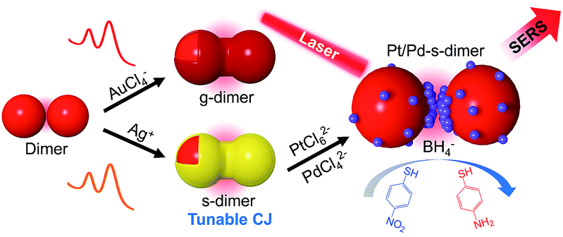
Light-excited collective and coherent movements of conduction electrons in a metal structure, termed localized surface plasmon resonance (LSPR),1–3 offer great opportunities in ultrafast optical nanocircuitry,4,5 information transport,6,7 light harvesting,8,9 sensing,10–12 nanomedicine,13,14 and various hot-electron-mediated processes.15–17 Particularly, the LSPRs of nanoparticles (NPs) in close vicinity can hybridize into new resonance modes.18–20 In the case of gold nanoparticle (AuNP) dimers with a small dielectric gap, a bonding dipolar plasmon (BDP) exists at a low energy level due to strongly coupled electric dipoles.18–21 The BDP results in charge piling-up and sub-diffractional light trapping (nanofocus) inside the nanogap.22–25 Once a capacitive nanogap is shorted, charge neutralization will happen, accompanied by the formation of a charge transfer plasmon (CTP).20,21,24–27 The CTP delivers a facile way for plasmonic tuning well into the near infrared (NIR) domain,24–27 signaling the electron transport properties of the junction materials at optical frequencies.26,28Compared to photolithography, solution-processing techniques are superior in the composition, crystallinity, and 3D shape control of plasmonic nanostructures.29–34 In particular, DNA nanotechnology has enabled programmable assembly of inorganic building blocks into prescribed structures.35–37 However, a strong capacitive coupling or direct charge transfer is often prohibited in these assemblies by the bulky DNA strands.38,39 To circumvent this problem, dried samples (unexpected due to structural disruption) are often used, as capillary forces generated during water evaporation can bring NPs in close contact.40–42 Apart from self-assembly, direct synthesis of interfaced plasmonic nanodimers is possible but producing gapped structures is hard.29–31 A method based on combined optical-electrochemical processes has been reported for in situ growth of NP patterns.43,44 However, it is difficult to achieve spacing control with nanometer accuracy. We developed a facile and highly efficient Ag ion soldering (AIS) strategy to make subnm-gapped nanofoci.45 The strong coupling enabled by AIS and its adaptability to DNA nanotechnology provided a tool to realize hybridized LSPRs of plasmonic “molecules”.46 Upon thermal reshaping, tunable CTPs up to the NIR II regime were obtained.47,48 However, the lack of chemical tunability severely limited the application of the nanofoci. To surpass this barrier, spatially addressable chemical modifiability should be achieved for the subnm gaps without compromising on their light focusing ability.
Herein we report a novel class of chemically modified nanofoci (CMNFs) as the smallest compound (dimer) structures with unified plasmonic/catalytic functions (Scheme 1). From a kinetic point of view, the hindered mass transport to the ultra-narrow and recessed nanogap of the AuNP dimer does not favor chemical modification (e.g. metal deposition) inside the nanofocus. Favorably, thermodynamics supports gap filling to minimize the dimer's interfacial energy. Accordingly, the CMNFs can be formed under properly chosen conditions to overcome the kinetic barrier. In this process, the subnm gap achieved by AIS is highly beneficial to prime the junction growth. The tunable chemical activities of the CMNFs clearly distinguish them from structures made by purely physical processes.47,48 The resulting Au or Ag conductive junction (CJ) in a dimer allows highly efficient CTP reshaping. The Ag CJ can be converted into Pt/Pd catalysts via galvanic displacement, enabling surface enhanced Raman spectroscopy (SERS) monitoring of catalytic reactions at the nanofocus.49,50 Therefore, the catalytic activities provided by the in-hotspot metal deposits and the plasmon-enabled SERS probing can work together cooperatively. In particular, the CMNFs with definable plasmonic and catalytic properties may help in the pursuit of new chemistry in the strongly boosted optical near-field.51–53 Note that direct assembly of catalytic Pt or Pd-based NPs as in our previous work could not generate intensified light fields for the above applications due to their heavily damped plasmon resonances.45
 | ||
| Scheme 1 Schematic illustration of a chemical route to realize gap-engineered AuNP dimers for charge transfer plasmon reshaping and in-hotspot catalytic reaction. | ||
Results and discussion
Bis(p-sulfonatophenyl) phenyl phosphine (BSPP) capped AuNPs with diameters of 23, 30, and 43 nm (ESI, Fig. S1†) were employed to make nanodimers via an AIS process.45 The resulting AuNP clusters were electrophoresed in an agarose gel to isolate dimeric assemblies (ESI, Fig. S2†). The AIS relies on ligand stripping from the AuNPs driven by the formation of a stable BSPP–Ag+ complex.45 The resulting ligand-deficient AuNPs are very “sticky”, which immediately form discrete clusters in the presence of a fish sperm DNA stabilizer. Extinction spectra (ESI, Fig. S3†) suggested strong coupling of the gel-purified AuNP dimers (ESI, Fig. S4†) according to their BDP wavelengths. Computations revealed an interparticle gap of 0.65–0.9 nm (ESI, Fig. S3(d)†). Therefore, the bonding between NPs could be attributed to van der Waals attractive forces within a sub-nm distance based on the DLVO theory.54The super-narrow interparticle separation would facilitate nucleation of the Au or Ag junction in the dimeric gap during metal deposition. However, failures were experienced during our initial attempts (ESI, Fig. S5–S7†). We reasoned that a high reaction temperature would be able to increase the diffusivity of surface-deposited metal atoms to enter the gap areas, and enhance diffusional and convectional transports of chemicals into the gap vicinities. At an elevated temperature, desorption of FSDNA from the AuNPs would happen, followed by citrate backfilling to provide an activated surface for the metal deposition. Accordingly, Au and Ag conductive junctions (CJs) could be formed in the nanogaps with citrate ions as both the reducing and surface-capping agent. Due to the gap-preferred metal deposition, the CJs were controllable in width by simply altering HAuCl4 and AgNO3 concentrations (Fig. 1 and 2, panels a–c). The resulting CMNFs with gold and silver CJs were termed g-dimers and s-dimers, respectively. We measured the widths of the CJs and the diameters of the metal-deposited AuNPs based on transmission electron microscopy (TEM) images. The statistical data in ESI Fig. S8–S11† suggested more Au and Ag deposits in the nanofoci, possibly due to surface atom rearrangements. The gap-directed metal deposition was more obvious for the s-dimers due to the high diffusivity of Ag atoms.55 Such a growth mode was also supported by energy dispersive X-ray (EDX) spectral analysis (ESI, Fig. S12†) of the s-dimer product.
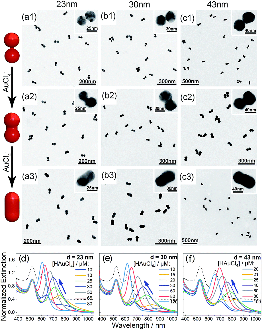 | ||
| Fig. 1 (a–c) TEM images of the as-synthesized g-dimers with increased gold deposition (1–3) based on 23 (a), 30 (b), and 43 nm (c) AuNPs. Insets are magnified views of the CMNFs. (d–f) Extinction spectra of AuNP dimers after gold deposition to form tunable CTPs. Dotted curves indicate the BDP peaks (located at the right side of the 520 nm resonances) of unmodified dimers. | ||
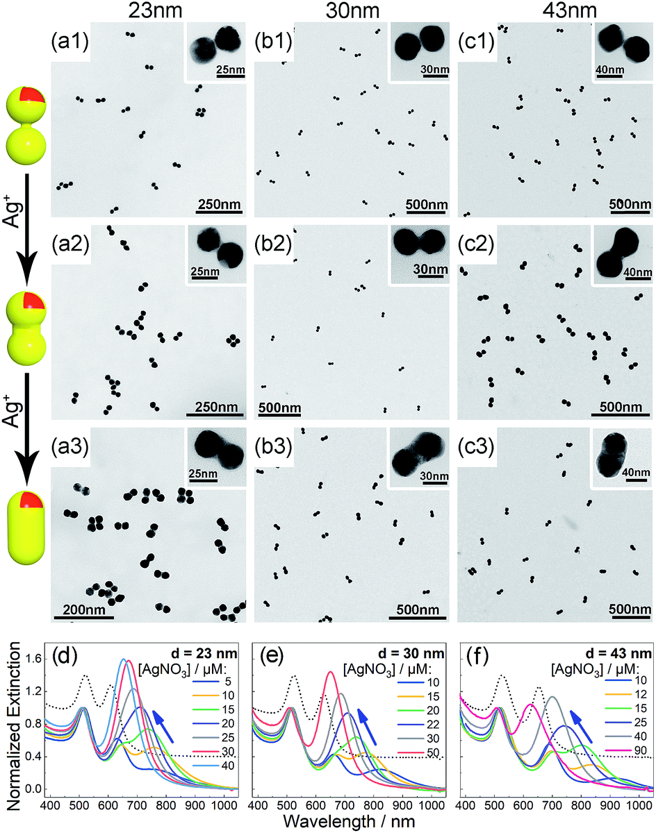 | ||
| Fig. 2 (a–c) TEM images of the as-synthesized s-dimers with increased Ag deposition (1–3) based on 23 (a), 30 (b), and 43 nm (c) AuNPs. Insets are magnified views of the CMNFs. (d–f) Extinction spectra of AuNP dimers after silver deposition to form tunable CTPs. Dotted curves indicate the BDP peaks (located at the right side of the 520 nm resonances) of unmodified dimers. | ||
A visual sign for the formation of Au and Ag CJs was based on CTP-induced solution color transitions (ESI, Fig. S13 and S14†) due to plasmonic light scattering and absorbance. To rule out aggregation-induced color changes and any color mixing effects caused by structural heterogeneity, agarose gel electrophoresis (AGE) was conducted. All samples appeared as single, sharp gel bands with characteristic colors identical to their native solutions (ESI, Fig. S15 and S16†), which exclusively verified that the as-observed colors were from monodisperse CMNFs. Consistently, extinction spectra (Fig. 1 and 2, panels d–f) showed CTP resonances at significantly longer wavelengths than those of the gap-mode BDPs. These CTP peaks gradually shifted from the NIR to visible region when more Au and Ag deposits entered the nanofoci. The spectral trend was reasonable as a thickened CJ allows higher frequency electron shuttling between two AuNPs.20,21,24,26,27 Meanwhile, the BDP immediately diminished upon the formation of CJs due to charge neutralization.21–27 The CTP frequency depends on the junction width (w) and the NP size (d), and thus a small w/d results in a long CTP wavelength. Theoretical plasmonic responses of the g- and s-dimers were obtained by solving full Maxwell's equations with a boundary element method (BEM).56 The CJ widths were optimized during the simulations to fit experimental CTPs. A good match was achieved between theoretical and measured CJ widths (ESI, Fig. S17†). We further relied on simulations to reveal different CTP behaviors of the CMNFs with metal layers confined in the gap or on the whole dimer surface (ESI, Fig. S18†). These two scenarios produced similar CTP maxima.
The as-prepared s-dimers were sensitive to oxidative etching by H2O2 which caused a redshift of their CTPs back to the NIR region (ESI, Fig. S19 and S20†). TEM images evidenced the H2O2 etched CMNFs (ESI, Fig. S21†). Interestingly, even in the presence of excess H2O2, the CTP peak did not completely disappear. This fact indicated high stability of some residual silver due to the electron-drawing effect from the underlying gold,57,58 which was responsible for maintaining the conductive contact between two AuNPs. Therefore, we could easily achieve a CTP close to 1000 nm without breaking the dimeric assembly. Because H2O2 is a common reactant or product of enzymatic reactions, such a CTP tuning would find applications in chemical and biological sensing.
The gold dimers are ideal antennas capable of concentrating light in their nanogaps. We therefore expected to realize unified plasmonic and catalytic functions in a single CMNF structure. Such structures are valuable for plasmon-enabled in situ Raman probing of catalytic conversions. One key challenge was to introduce catalyst materials into the nanosized gaps without causing a significant loss of their light focusing ability. The s-dimers allowed us to realize such otherwise hard-to-make structures by galvanic displacement of pre-formed Ag junctions with Pt and Pd catalysts. The metal displacement was monitored based on a redshift of the CTP peak due to reduced CJ conductance (ESI, Fig. S22†). Finalization of this process was verified by H2O2-etching which did not cause further spectral changes due to silver loss. To facilitate TEM observations, s-dimers with relatively thick Ag CJs were initially employed. Fig. 3 verifies the formation of discrete Pt and Pd deposits in and outside of the nanofoci along with the disappearance of the Ag CJs after the galvanic displacements. Despite the successful Pt/Pd modifications, the resulting CMNFs had significantly weakened BDP unsuitable for light focusing. We therefore employed s-dimers bearing the thinnest Ag CJs (also improved regioselectivity of Ag deposition) to minimize gap expansions, which was justifiable since catalytic activities mostly come from several atomic layers of a catalyst phase. While these s-dimers caused difficulty in visualizing the Pt/Pd deposits (ESI, Fig. S23†), we could confidently judge the metal displacement from the weakened and redshifted CTP profiles (ESI, Fig. S24†). The as-produced CMNFs (termed Pt-s-dimer and Pd-s-dimer) could catalyze the hydrogenation of 4-nitrothiophenol (4-NTP) at the nanofoci, and give plasmonic nanogap-enhanced Raman signals in the meantime.
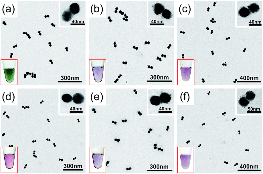 | ||
| Fig. 3 TEM images showing the s-dimers (a and d), Pt-s-dimers (b and e), and Pd-s-dimers (c and f) before (a–c) and after (d–f) H2O2 etching to verify the displacement of silver. Insets are magnified TEM views of the CMNFs and photos of their solutions. | ||
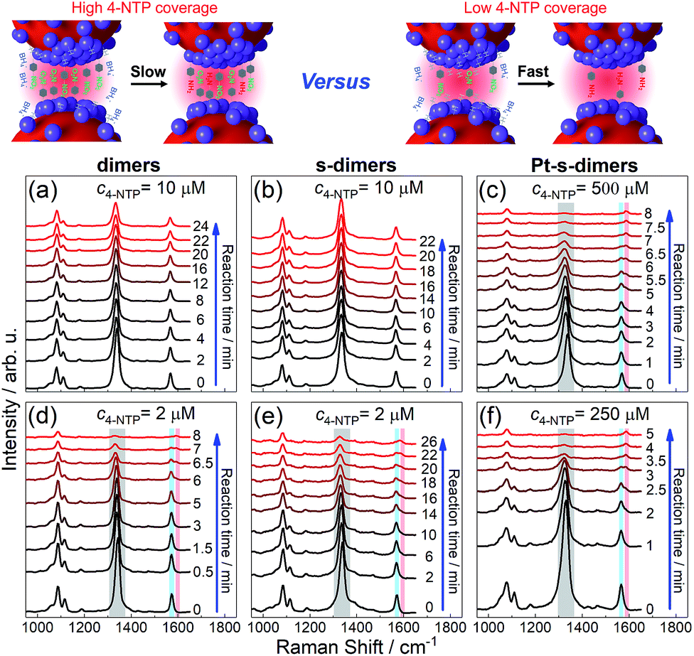
Three SERS vibrations of 4-NTP at 1090, 1340, and 1573 cm−1 were observed for AuNP dimers and the corresponding CMNF derivatives, corresponding to C–S and O–N–O stretching, and phenol-ring breathing modes, respectively (Fig. 4 and S25 in ESI†).59 At high 4-NTP coverage (incubated with 10 μM 4-NTP to achieve close-to-saturation adsorption), the AuNP dimers and s-dimers only showed slightly attenuated SERS intensities due to NaBH4-induced 4-NTP desorption. In sharp contrast, the Pt-s-dimers showed quick diminishing of the 1340 and 1573 cm−1 peaks upon adding NaBH4 at a much higher 4-NTP incubation concentration (500 μM) to achieve close-to-saturation adsorption. Such a change was accompanied by the appearance of a new vibration at 1593 cm−1, corresponding to the phenol-ring mode of 4-ATP (4-aminothiophenol, a reduced form of 4-NTP). The final product had a SERS profile similar to that of 4-ATP (ESI, Fig. S26†), mirroring a selective hydrogenation of the nitro group. At lowered 4-NTP coverage, the dimers and all CMNFs gave SERS signals reflecting the consumption of 4-NTP along with the concomitant formation of 4-ATP. Note that the 4-NTP was only diluted by half as shown in Fig. 4(f), otherwise it would be hard to track the very quick reaction. The weaker reactivity at high 4-NTP coverage was attributed to the self-passivation of catalytic sites by 4-NTP which blocked away the co-adsorptive BH4− and hydrogen species. The inertness of s-dimers contrasted sharply with Pt- and Pd-s-dimers, providing extra evidence for the successful Pt and Pd modifications. Both extinction and TEM data showed negligible alterations to the reacted CMNFs (ESI, Fig. S27 and S28†), which guaranteed the reliability of our SERS measurements.
 | ||
| Fig. 4 SERS tracking of NaBH4-based hydrogenation of 4-NTP adsorbed on AuNP dimers (a and d), s-dimers (b and e), and Pt-s-dimers (c and f) with 4-NTP incubation concentrations indicated on each panel. See Fig. S25† for kinetic SERS data of Pd-s-dimers. | ||
It should be mentioned that the SERS signals were from homogeneously dispersed solution samples with good reproducibility. The 4-ATP was a product of chemical catalysis such that its yield clearly depended on the incubation time between 4-NTP and NaBH4 (ESI, Fig. S29†). The plasmon-driven dimerization of 4-NTP into 4,4′-dimercaptoazobenzene (DMAB) could also be monitored by SERS in a different way with the CMNFs being deposited on a solid substrate. The immobilized CMNFs avoided the diffusion of DMAB out of the focus of the Raman probing laser (ESI, Fig. S30†). Note that the plasmon-induced process did not interfere with the SERS-based monitoring of the chemical catalysis due to different sample preparations (solid vs. solution-based samples).
Considering the unrivaled programmability of DNA in making self-assembled structures,35–37 it is highly desired to make our strategy compatible with DNA nanotechnology. To demonstrate this possibility, DNA-linked AuNP dimers were treated by AIS to achieve a strong coupling.46 The AIS treatment helped the formation of an Au or Ag CJ between two AuNPs during metal deposition (ESI, Fig. S31†). In contrast, DNA-linked dimers without the AIS treatment completely dissociated due to heat-denaturation. Optical extinctions revealed a big difference between the products with and without the AIS treatment (ESI, Fig. S32†). Besides, DNA conjugation was possible for the g-dimers to enable DNA-programmable core–satellite assembly (ESI, Fig. S33†).
Conclusions
In conclusion, we have successfully realized a novel family of chemically modified nanofoci with accurately definable and unified plasmonic and catalytic activities. The conductively linked gold nanodimers by Au or Ag junctions lead to charge transfer plasmons with tunable wavelengths up to 1000 nm. By in situ conversion of the silver junctions into Pt and Pd deposits via galvanic displacement, catalytic functions are integrated into the nanofoci without causing a loss of their light focusing ability. The catalytic CMNFs allow real-time, noninvasive, and on-site monitoring of chemical reactions inside the plasmonic nanogaps. The chemical modifications are compatible with DNA-bonded nanoassemblies, leading to DNA-programmable CMNFs. The ability to accurately engineer the plasmonic and catalytic functions of a self-assembled structure opens a new door to sensing, catalysis, spectral enhancements, and photochemistry. The next goal is to pursue light-driven (hotspot-enhanced) unconventional chemical pathways benefiting from the strongly focused light field unified with prescribed catalytic activities. Compared to nanoparticle aggregates or surface-deposited colloidal layers, the CMNFs are advantageous due to strong plasmonic coupling, structural purity, and chemical modification specificity. These features make them highly valued for a deep integration between plasmonics and chemistry with minimum ambiguity in structure–function relationships. The structural uniformity may also enable plasmonic and catalytic studies at the single nanoparticle level.Conflicts of interest
There are no conflicts of interest to declare.Acknowledgements
This work was supported by the National Key Research and Development Program of China (2016YFA0201300), the National Science Fund for Distinguished Young Scholars (21425521), the Foundation for Innovative Research Groups of the NNSFC (21521001), and the Collaborative Innovation Center of Suzhou Nano Science and Technology.Notes and references
- N. Jiang, X. Zhuo and J. Wang, Chem. Rev., 2018, 118, 3054–3099 CrossRef CAS PubMed.
- E. Hutter and J. H. Fendler, Adv. Mater., 2004, 16, 1685–1706 CrossRef CAS.
- V. Giannini, A. I. Fernández-Domínguez, S. C. Heck and S. A. Maier, Chem. Rev., 2011, 111, 3888–3912 CrossRef CAS PubMed.
- N. Engheta, Science, 2007, 317, 1698–1702 CrossRef CAS PubMed.
- N. Liu, F. Wen, Y. Zhao, Y. Wang, P. Nordlander, N. J. Halas and A. Alù, Nano Lett., 2013, 13, 142–147 CrossRef CAS PubMed.
- E. M. Roller, L. V. Besteiro, C. Pupp, L. K. Khorashad, A. O. Govorov and T. Liedl, Nat. Phys., 2017, 13, 761–765 Search PubMed.
- S. A. Maier, P. G. Kik, H. A. Atwater, S. Meltzer, E. Harel, B. E. Koel and A. A. G. Requicha, Nat. Mater., 2003, 2, 229–232 CrossRef CAS PubMed.
- Y. Nishijima, L. Rosa and S. Juodkazis, Opt. Express, 2012, 20, 11466–11477 CrossRef CAS PubMed.
- N. Zhou, V. López-Puente, Q. Wang, L. Polavarapu, I. Pastoriza-Santos and Q. H. Xu, RSC Adv., 2015, 5, 29076–29097 RSC.
- J. R. Mejía-Salazar and O. N. Oliveira Jr, Chem. Rev., 2018, 118, 10617–10625 CrossRef PubMed.
- K. M. Mayer and J. H. Hafner, Chem. Rev., 2011, 111, 3828–3857 CrossRef CAS PubMed.
- Y. Su, T. Peng, F. Xing, D. Li and C. Fan, Acta Chim. Sin., 2017, 75, 1036–1046 CrossRef CAS.
- E. Boisselier and D. Astruc, Chem. Soc. Rev., 2009, 38, 1759–1782 RSC.
- G. Chen, I. Roy, C. Yang and P. N. Prasad, Chem. Rev., 2016, 116, 2826–2885 CrossRef CAS PubMed.
- S. Linic, U. Aslam, C. Boerigter and M. Morabito, Nat. Mater., 2015, 14, 567–576 CrossRef CAS PubMed.
- J. Y. Park, S. M. Kim, H. Lee and I. I. Nedrygailov, Acc. Chem. Res., 2015, 48, 2475–2483 CrossRef CAS PubMed.
- I. I. Nedrygailov, H. Lee, S. W. Lee and J. Y. Park, Chin. Chem. Lett., 2018, 29, 727–733 CrossRef CAS.
- E. Prodan, C. Radloff, N. J. Halas and P. Nordlander, Science, 2003, 302, 419–422 CrossRef CAS PubMed.
- P. Nordlander and C. Oubre, Nano Lett., 2004, 4, 899–903 CrossRef CAS.
- N. J. Halas, S. Lal, W. S. Chang, S. Link and P. Nordlander, Chem. Rev., 2011, 111, 3913–3961 CrossRef CAS PubMed.
- I. Romero, J. Aizpurua, G. W. Bryant and F. J. G. de Abajo, Opt. Express, 2006, 14, 9988–9999 CrossRef PubMed.
- N. Liu, M. L. Tang, M. Hentschel, H. Giessen and A. P. Alivisatos, Nat. Mater., 2011, 10, 631–636 CrossRef CAS PubMed.
- W. Zhu, R. Esteban, A. G. Borisov, J. J. Baumberg, P. Nordlander, H. J. Lezec, J. Aizpurua and K. B. Crozier, Nat. Commun., 2016, 7, 11495 CrossRef CAS.
- K. J. Savage, M. M. Hawkeye, R. Esteban, A. G. Borisov, J. Aizpurua and J. J. Baumberg, Nature, 2012, 491, 574–577 CrossRef CAS.
- R. Esteban, A. G. Borisov, P. Nordlander and J. Aizpurua, Nat. Commun., 2012, 3, 825 CrossRef PubMed.
- O. Pérez-González, N. Zabala, A. G. Borisov, N. J. Halas, P. Nordlander and J. Aizpurua, Nano Lett., 2010, 10, 3090–3095 CrossRef.
- T. Atay, J. H. Song and A. V. Nurmikko, Nano Lett., 2004, 4, 1627–1631 CrossRef CAS.
- S. F. Tan, L. Wu, J. K. W. Yang, P. Bai, M. Bosman and C. A. Nijhuis, Science, 2014, 343, 1496–1499 CrossRef CAS.
- Y. Sun, J. J. Foley IV, S. Peng, Z. Li and S. K. Gray, Nano Lett., 2013, 13, 3958–3964 CrossRef CAS PubMed.
- J. H. Lee, M. H. You, G. H. Kim and J. M. Nam, Nano Lett., 2014, 14, 6217–6225 CrossRef CAS PubMed.
- W. Xu, Z. Li and Y. Yin, Small, 2018, 14, 1801083 CrossRef PubMed.
- Y. Hu and Y. Sun, J. Am. Chem. Soc., 2013, 135, 2213–2221 CrossRef CAS PubMed.
- M. Lin, G. H. Kim, J. H. Kim, J. W. Oh and J. M. Nam, J. Am. Chem. Soc., 2017, 139, 10180–10183 CrossRef CAS PubMed.
- Z. Wang, B. He, G. Xu, G. Wang, J. Wang, Y. Feng, D. Su, B. Chen, H. Li, Z. Wu, H. Zhang, L. Shao and H. Chen, Nat. Commun., 2018, 9, 563 CrossRef PubMed.
- N. C. Seeman, Nature, 2003, 421, 427–431 CrossRef PubMed.
- M. R. Jones, N. C. Seeman and C. A. Mirkin, Science, 2015, 347, 1260901 CrossRef PubMed.
- N. Liu and T. Liedl, Chem. Rev., 2018, 118, 3032–3053 CrossRef CAS PubMed.
- J. Y. Kim and N. A. Kotov, Chem. Mater., 2014, 26, 134–152 CrossRef CAS.
- L. Song and Z. Deng, ChemNanoMat, 2017, 3, 698–712 CrossRef CAS.
- A. Thill and O. Spalla, Langmuir, 2002, 18, 4783–4789 CrossRef CAS.
- P. A. Kralchevsky and K. Nagayama, Langmuir, 1994, 10, 23–36 CrossRef CAS.
- Z. Zhou, Q. Li and X. S. Zhao, Langmuir, 2006, 22, 3692–3697 CrossRef CAS PubMed.
- Y. B. Vogel, V. R. Gonçales, L. Al-Obaidi, J. J. Gooding, N. Darwish and S. Ciampi, Adv. Funct. Mater., 2018, 28, 1804791 CrossRef.
- Y. B. Vogel, J. Zhang, N. Darwish and S. Ciampi, ACS Nano, 2018, 12, 8071–8080 CrossRef CAS PubMed.
- M. Liu, L. Fang, Y. Li, M. Gong, A. Xu and Z. Deng, Chem. Sci., 2016, 7, 5435–5440 RSC.
- H. Wang, Y. Li, M. Liu, M. Gong and Z. Deng, Small, 2015, 11, 2247–2251 CrossRef CAS PubMed.
- L. Fang, Y. Wang, M. Liu, M. Gong, A. Xu and Z. Deng, Angew. Chem., Int. Ed., 2016, 128, 14508–14512 CrossRef.
- L. Fang, D. Liu, Y. Wang, Y. Li, L. Song, M. Gong, Y. Li and Z. Deng, Nano Lett., 2018, 18, 7014–7020 CrossRef CAS PubMed.
- S. Ding, J. Yi, J. Li, B. Ren, D. Wu, R. Panneerselvam and Z. Tian, Nat. Rev. Mater., 2016, 1, 16021 CrossRef CAS.
- C. Wang, L. Tian, W. Zhu, S. Wang, N. Gao, K. Zhou, X. Yin, W. Zhang, L. Zhao and G. Li, Chem. Sci., 2018, 9, 889–895 RSC.
- U. Aslam, S. Chavez and S. Linic, Nat. Nanotechnol., 2017, 12, 1000–1005 CrossRef CAS PubMed.
- A. S. Alnaser, M. Kübel, R. Siemering, B. Bergues, N. G. Kling, K. J. Betsch, Y. Deng, J. Schmidt, Z. A. Alahmed, A. M. Azzeer, J. Ullrich, I. Ben-Itzhak, R. Moshammer, U. Kleineberg, F. Krausz, R. de Vivie-Riedle and M. F. Kling, Nat. Commun., 2014, 5, 3800 CrossRef CAS PubMed.
- A. C. Aragonès, N. L. Haworth, N. Darwish, S. Ciampi, N. J. Bloomfield, G. G. Wallace, I. Diez-Perez and M. L. Coote, Nature, 2016, 531, 88–91 CrossRef PubMed.
- T. Cosgrove, Colloid Science: Principles, Methods and Applications, John Wiley & Sons, West Sussex, 2010 Search PubMed.
- W. C. Mallard, A. B. Gardner, R. F. Bass and L. M. Slifkin, Phys. Rev., 1963, 129, 617–625 CrossRef CAS.
- U. Hohenester and A. Trügler, Comput. Phys. Commun., 2012, 183, 370–381 CrossRef CAS.
- H. Wang, Y. Li, M. Gong and Z. Deng, Chem. Sci., 2014, 5, 1015–1020 RSC.
- D. T. N. Anh, P. Singh, C. Shankar, D. Mott and S. Maenosono, Appl. Phys. Lett., 2011, 99, 073107 CrossRef.
- W. Xie and S. Schlücker, Chem. Commun., 2018, 54, 2326–2336 RSC.
Footnote |
| † Electronic supplementary information (ESI) available: Methods and extra supporting figures. See DOI: 10.1039/c9sc00403c |
| This journal is © The Royal Society of Chemistry 2019 |