 Open Access Article
Through-space charge transfer hexaarylbenzene dendrimers with thermally activated delayed fluorescence and aggregation-induced emission for efficient solution-processed OLEDs†
Xingdong
Wang
,
Shumeng
Wang
,
Jianhong
Lv
,
Shiyang
Shao
 *,
Lixiang
Wang
 *,
Xiabin
Jing
and
Fosong
Wang
State Key Laboratory of Polymer Physics and Chemistry, Changchun Institute of Applied Chemistry, Chinese Academy of Sciences, Changchun 130022, P. R. China. E-mail: ssyang@ciac.ac.cn; lixiang@ciac.ac.cn
First published on 14th January 2019
Abstract
Through-space electron interaction plays a critical role in determining the optical and charge transport properties of functional materials featuring π-stacked architectures. However, developing efficient organic luminescent materials with such interactions has been a challenge because of the lack of well-established prototypical molecules. Here we report the design of through-space charge transfer hexaarylbenzenes (TSCT-HABs) containing circularly-arrayed electron donors (acridan/dendritic triacridan) and acceptors (triazine), which exhibit both thermally activated delayed fluorescence (TADF) and aggregation-induced emission (AIE) effects for high-efficiency solution-processed organic light-emitting diodes (OLEDs). Spatial separation of donors and acceptors in the TSCT-HABs induces a small singlet–triplet energy splitting of 0.04–0.08 eV, leading to delayed fluorescence with microsecond-scale lifetimes. Meanwhile, the TSCT-HABs display the AIE effect with emission intensity enhanced by 6–17 fold from solution to the aggregation state owing to their propeller-shaped configuration. Solution-processed OLEDs based on the TSCT-HABs show maximum external quantum efficiency up to 14.2%, making them among the most efficient emitters for solution-processed TADF OLEDs.
1 Introduction
Charge transfer (CT) is a fundamental and crucial process in π-conjugated systems and π-stacked systems.1,2 Organic luminescent materials with charge transfer emission have enabled important applications such as organic light-emitting diodes (OLEDs),3–11 chemical sensors,12,13 and bioimaging.14,15 So far, the charge transfer process can be divided into two categories according to the electron interaction pattern. One is through-bond charge transfer (TBCT) which is mediated by conjugated bonds,16–21 and the other is through-space charge transfer (TSCT) which occurs through spatial π–π interaction.22–24 Different from TBCT emitters that feature strong electron coupling through covalent bonds, the TSCT ones provide a scaffold for weak electron interaction between donors and acceptors through space.25,26 This character provides us a new viewpoint to design novel organic luminescent materials with promising properties.Hexaarylbenzene (HAB) derivatives,27 in which six aromatic rings are arranged around the central phenyl ring in close proximity, can be considered as a desired model to investigate the TSCT process. Because of the steric hindrance of the six aromatic rings, HAB has a nonplanar structure with a propeller-shaped configuration in which the peripheral aromatic units are almost perpendicular to the central phenyl ring.28 This conformation forces the aromatic units to face each other, enabling the through-space electron interactions between the aromatic rings in the periphery.29 By decorating the hexaphenylbenzene core with suitable donors and acceptors, HABs with redox chromophores have been constructed to show interesting properties and applications such as fluoride ion probing and organic amine recognition in recent years.26,30
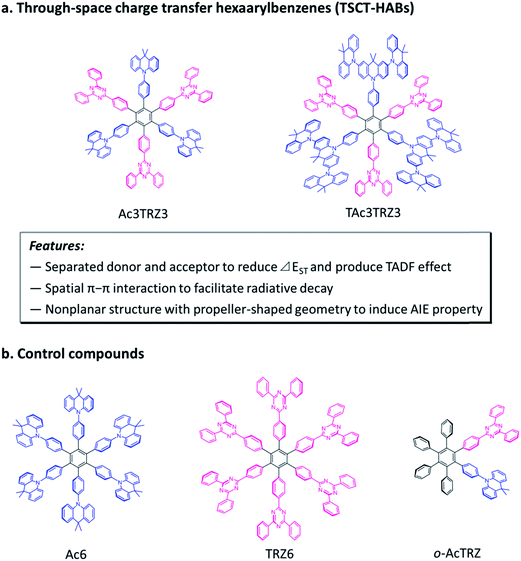
Here we demonstrate through-space charge transfer hexaarylbenzenes (TSCT-HABs) with circularly-arrayed donors (acridan/dendritic triacridan) and acceptors (triazine) in the periphery of the hexaphenylbenzene core, exhibiting both the thermally activated delayed fluorescence (TADF) property and aggregation-induced emission (AIE) effect for high-efficiency solution-processed organic light-emitting diodes (OLEDs) (Fig. 1). This molecular design is expected to have the following features. First, unlike conventional TBCT emitters where the electron clouds of donors and acceptors can overlap around the linkages, those of TSCT-HABs are physically separated, which is favorable for reducing the singlet–triplet energy splitting (ΔEST) and producing the TADF effect. Second, because of the relatively close distance between adjacent donors and acceptors in the TSCT-HABs, through-space electron interaction can occur to facilitate the radiative transition needed for efficient emission. Finally, the nonplanar, propeller-shaped structures of TSCT-HABs allow them to exhibit the AIE property through the restricted intramolecular motion (RIM) mechanism,31 which is favorable for enhancing their solid-state emission efficiencies. Therefore, the TSCT-HAB framework could provide a unique platform for us to design highly-emissive materials featuring both the TADF property and AIE effect that are desired for the development of high-efficiency OLEDs.
2 Results and discussion
2.1 Molecular design and synthesis
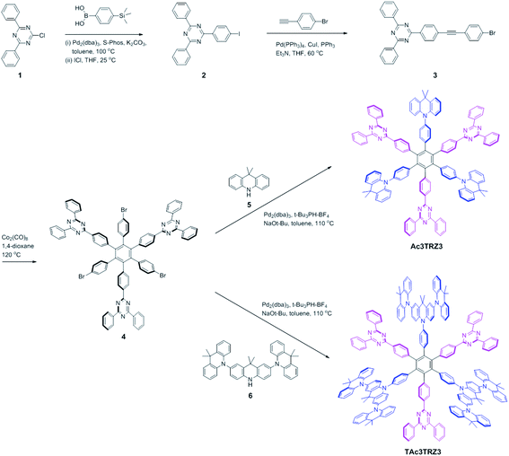
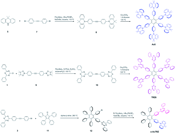
Two kinds of TSCT-HABs are designed and prepared by introducing three electron donors and three electron acceptors into the periphery of the hexaphenylbenzene core. One is Ac3TRZ3 containing acridan (Ac) as the donor and triazine (TRZ) as the acceptor. The other is TAc3TRZ3 that consists of dendritic teracridan (TAc) with a stronger electron-donating ability as the donor and TRZ as the acceptor, aiming to investigate the influence of charge transfer strength on the photophysical properties. Moreover, to explore the origin of the charge transfer emission, two kinds of model compounds are also designed: one is Ac6 and TRZ6 that contain six Ac donors or six TRZ acceptors around the hexaphenylbenzene core, while the other is o-AcTRZ containing one pair of the Ac donor and TRZ acceptor in ortho-positions of the central phenyl ring (Fig. 1b). The synthesis procedure of the compounds is given in Schemes 1 and 2. The synthesis was initiated with 2-chloro-4,6-diphenyl-1,3,5-triazine (1) which underwent Suzuki reaction with (4-(trimethylsilyl)phenyl)boronic acid and then deprotection of the trimethylsilyl group to afford the iodide 2. Selective Sonogashira coupling between 2 and 1-bromo-4-ethynylbenzene produced the arylacetylene 3 in an acceptable yield (54%). The key tribromohexaarylbenzene intermediate 4 for Ac3TRZ3 and TAc3TRZ3 was synthesized by a cobalt-catalyzed cyclotrimerization procedure32,33 from the arylacetylene precursor 3, which then went through palladium-catalyzed Buchwald-Hartwig coupling with acridan 5 or teracridan 6 to produce the compounds Ac3TRZ3 and TAc3TRZ3 in moderate yields (34–47%). For Ac6 and TRZ6, the direct cyclotrimerization of the diarylacetylenes 8 and 10 containing acridan or 2,4-biphenyltriazine units at each terminal gives the desired products. The synthesis of o-AcTRZ was based on a monobromohexaphenylbenzene derivative 12 produced from arylacetylene 3 and tetraphenylcyclopentadienone 11via Diels–Alder reaction, which was coupled with acridan under palladium catalysis. Both Ac3TRZ3 and TAc3TRZ3 show excellent thermal stability with decomposition temperatures (Tds) higher than 380 °C and glass transition temperatures (Tgs) of 175–181 °C (Fig. S1, ESI†). In addition, they exhibit good solubility in common organic solvents such as toluene, tetrahydrofuran (THF), chloroform, chlorobenzene and so on, implying that they are suitable for solution processing.To simulate the geometry configuration and frontier molecular orbitals of the TSCT-HABs, density functional theory (DFT) calculations were performed at the b3lyp/6-31g(d) level (Fig. 2). In the optimized ground-state configurations of Ac3TRZ3 and TAc3TRZ3, the peripheral phenyl rings of the hexaphenylbenzene moieties are almost orthogonal to the central phenyl ring, which is the typical geometry for HABs.27 This configuration leads to reduced electron interaction of the donor and acceptor through the central phenyl ring. In addition, the highest occupied molecular orbitals (HOMOs) of Ac3TRZ3 and TAc3TRZ3 are distributed over the electron donors (Ac and TAc units), while the lowest unoccupied molecular orbitals (LUMOs) are mainly localized on the electron accepting TRZ units (see Fig. S2† for all the degenerate orbitals). Accordingly, it can be deduced that charge transfer occurs mainly through space mediated by spatial π–π interaction of the neighboring donors and acceptors, which is consistent with the electron cloud distributions observed in o-AcTRZ. On the other hand, since the HOMO and LUMO distributions are well separated, small ΔEST values could be expected for the TSCT-HABs. According to the time-dependent density functional theory (TD-DFT) calculations, Ac3TRZ3 shows very close singlet state (S1) and triplet state (T1) energy levels with the ΔEST estimated to be only 0.0007 eV, which is similar to that of o-AcTRZ (0.0006 eV). For TAc3TRZ3, an even smaller ΔEST value of 0.0002 eV is obtained. The small ΔEST values make these emitters promising candidates with the TADF property.
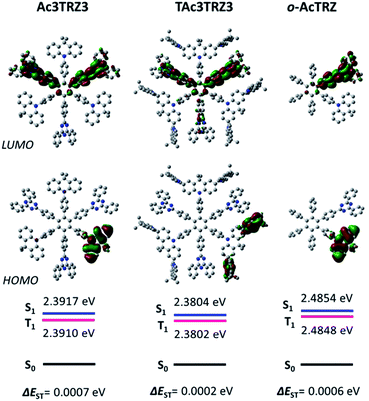 | ||
| Fig. 2 HOMO/LUMO distributions of Ac3TRZ3, TAc3TRZ3 and o-AcTRZ calculated at the b3lyp/6-31g(d) level. S1/T1 energies are calculated according to the TD-DFT method at the same level. | ||
2.2 Through-space charge transfer (TSCT) emission
PL spectra of the TSCT-HABs in toluene with a concentration of 10−5 mol L−1 are shown in Fig. 3. It is clear that Ac3TRZ3 shows a broad featureless emission as o-AcTRZ does with the peak (λem,max, 486 nm) red-shifted by 72 nm and 106 nm relative to Ac6 (λem,max = 414 nm) and TRZ6 (λem,max = 380 nm), respectively, which is assigned to the charge transfer emission between the electron-donating Ac and electron-accepting TRZ unit. Compared with Ac3TRZ3, TAc3TRZ3 exhibits a longer emission wavelength at 508 nm, implying that the stronger electron-donating ability of dendritic teracridan induces a much stronger charge transfer effect. Moreover, the emission of the TSCT-HABs shows a strong positive solvation effect (Fig. 3c and S4†). Taking Ac3TRZ3 as an example, as the solvent goes from cyclohexane to THF, the λem,max shifts from 440 nm to 542 nm. This observation implies that the TSCT-HABs have a small dipole moment in the ground state and a high dipole moment in the excited CT state. To get insight into the excited state, the Stokes shift (va − vf) of the TSCT-HABs against solvent orientation polarizability (Δf) is plotted according to the Lippert–Mataga equation.34,35 As shown in Fig. 3d, both Ac3TRZ3 and TAc3TRZ3 obey the linear relationship predicted by the Lippert–Mataga equation. Notably, the slope of the fitted curve for Ac3TRZ3 is very close to that of o-AcTRZ, confirming that the lowest excited state of Ac3TRZ3 is localized within one donor–acceptor pair similar to the situation in o-AcTRZ. In a solid-state film, Ac3TRZ3 and TAc3TRZ3 show similar charge transfer emissions as in solution with the peaks located at 505 nm and 518 nm, respectively. The photoluminescence quantum yield (PLQY) determined by integrating sphere is 20% for an Ac3TRZ3 neat film, which is increased to 54% by doping in Ac6 (10 wt%) to reduce the intermolecular exciton quenching. In comparison, TAc3TRZ3 with dendritic teracridan exhibits higher PLQYs of 36% and 63% for neat and doped films, respectively, indicating that charge transfer transition mediated by spatial π–π interaction is more efficient in TAc3TRZ3 than in Ac3TRZ3. To determine the triplet energy levels, phosphorescent spectra of Ac3TRZ3 and TAc3TRZ3 were measured in toluene at 77 K (Fig. S5, ESI†). According to the highest vibronic emission peaks, the triplet energy levels of Ac3TRZ3 and TAc3TRZ3 are determined to be 2.69 eV and 2.66 eV, respectively, giving experimental ΔEST values of 0.08 eV for Ac3TRZ3 and 0.04 eV for TAc3TRZ3. Such ΔEST values are small enough to facilitate the reverse intersystem crossing (RISC) process and produce the TADF effect.3,36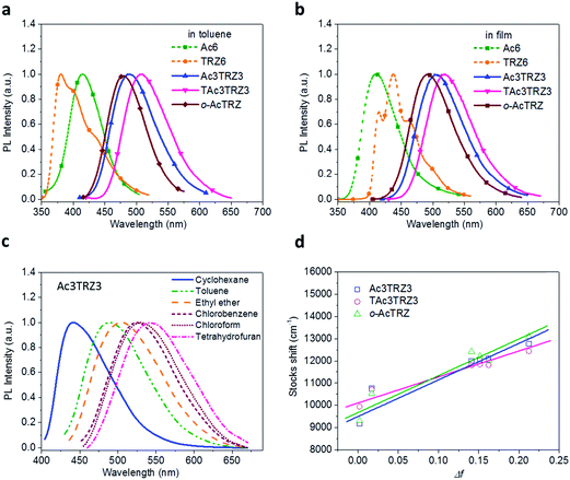 | ||
| Fig. 3 Steady-state photophysical properties of the TSCT-HABs. PL spectra of the TSCT-HABs in toluene (10−5 mol L−1) (a) and in the film state (b), PL spectra of Ac3TRZ3 in solvents with different polarity (c), and the linear correlation of orientation polarization (Δf) of the solvent with the Stokes shift for the TSCT-HABs (d) (see Table S1† for data). | ||
2.3 Thermally activated delayed fluorescence (TADF) effect
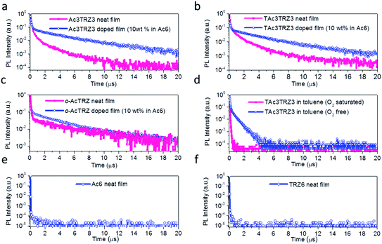
To investigate the TADF effect, transient PL decay characteristics of the TSCT-HABs were measured. As shown in Fig. 4a and b, both the Ac3TRZ3 and TAc3TRZ3 doped films (10 wt% in Ac6) show biexponential decay curves consisting of a prompt component and a delayed component. The lifetimes of the delayed components (τd) are calculated to be 3.54 μs and 3.16 μs with weight ratios of 77% and 87% for Ac3TRZ3 and TAc3TRZ3, respectively. Consequently, RISC rate constants (kRISC) of the Ac3TRZ3 and TAc3TRZ3 doped films are calculated to be 1.0 × 10⁶ s−1 and 2.1 × 10⁶ s−1, respectively, suggesting a favorable RISC process from the T1 state to S1 state.37,38 Compared with the doped films, the neat films of Ac3TRZ3 and TAc3TRZ3 show more complicated multi-exponential decay curves with the tail extending to 20 μs, probably because the intermolecular interactions in neat films result in an extra deactivation pathway for the excitons. Similar delayed emission behavior is also observed for o-AcTRZ where the charge transfer emission from the neighboring donor–acceptor pair exhibits both prompt and delayed components as Ac3TRZ3 does (Fig. 4c). To confirm that the delayed emission comes from the triplet state, PL decay curves of TAc3TRZ3 in O2 or N2 saturated toluene were recorded (Fig. 4d). It was found that the delayed emissions only exist in O2 free toluene, indicating that they originated from triplet excitons that can be quenched by O2 molecules. Finally, PL decay characteristics of Ac6 and TRZ6 containing only donors or acceptors were also measured for comparison. As shown in Fig. 4e and f, both Ac6 and TRZ6 show only prompt fluorescence emission with lifetimes at the nanosecond scale (10–12 ns), proving that the delayed emissions observed in Ac3TRZ3 and TAc3TRZ3 come from the electron interactions between the donors and the acceptors.2.4 Aggregation-induced emission (AIE) effect
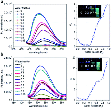
The AIE behavior of Ac3TRZ3 and TAc3TRZ3 was observed by measuring their PL spectra in THF/water mixed solvents via varying the water fraction (fw). As indicated in Fig. 5, Ac3TRZ3 in pure THF solution (fw = 0) shows a relatively weak emission at ∼540 nm. As fw increases to 0.4, the emission is slightly red-shifted which is accompanied by a gradually reduced intensity, probably because adding water to THF can increase the solvent polarity, leading to an enhanced charge transfer character and lower quantum yield. However, further increasing fw from 0.4 to 0.95 produces a dramatic increase of emission with an intensity of ∼6 times higher than that of the initial THF solution. Similar behavior is also observed for TAc3TRZ3, which shows an even greater enhancement of emission intensity by ∼17 fold as the fw increases from 0 to 0.95. Since the TSCT-HABs form aggregates in large water fractions, nonradiative channels induced by intramolecular motions can be suppressed, leading to enhanced fluorescence emission. This behavior is consistent with that of the propeller-shaped AIE emitters (such as hexaphenylsilole,39,40 pentaphenylpyrrole41 and tetraphenylethene42,43 derivatives) where the emission can be enhanced in the aggregation state through the restriction of intramolecular motion (RIM) mechanism.312.5 Solution-processed organic light-emitting diodes (OLEDs)
To investigate the EL performance, two kinds of solution-processed OLEDs were fabricated with the configuration of ITO/poly(3,4-ethylenedioxythiophene):poly(styrenesulfonate) (PEDOT:PSS) (40 nm)/emissive layer (EML) (40 nm)/diphenyl(4-(triphenylsilyl)phenyl)phosphine oxide (TSPO1)44 (8 nm)/1,3,5-tri(m-pyrid-3-yl-phenyl)benzene (TmPyPB)45 (42 nm)/LiF (1 nm)/Al (100 nm) (Fig. S7†). One is a non-doped device with EMLs of Ac3TRZ3 or TAc3TRZ3 neat films, the other is a doped device with EMLs of Ac3TRZ3 or TAc3TRZ3 doped in Ac6 at a concentration of 10 wt%. In the non-doped device, Ac3TRZ3 shows EL emission peaked at 520 nm, which is red-shifted to 538 nm for TAc3TRZ3 because of its stronger charge transfer effect (Fig. S8†). For the doped device, the EL emission of Ac3TRZ3 and TAc3TRZ3 is blue-shifted to 492 nm and 503 nm respectively, indicating that intermolecular interactions of the emitters are reduced. The emission from Ac6 is not observed in the doped devices, implying that the energy transfer from Ac6 to Ac3TRZ3 and TAc3TRZ3 is efficient in the EML (Fig. 6a).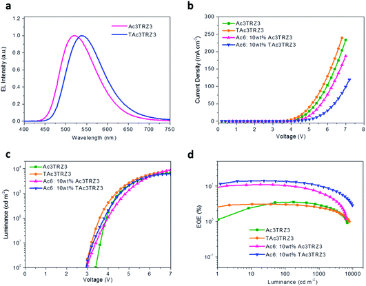 | ||
| Fig. 6 Device performance of the solution-processed OLEDs. EL spectra at 7 V (a), J–V (b) and L–V characteristics (c), together with EQE as a function of luminance (d) of the TSCT-HABs. | ||
Fig. 6b and d show the current density (J)–voltage (V) and luminance (L)–voltage (V) characteristics, as well as the luminance dependence of external quantum efficiency (EQE) for the two kinds of devices. The device performance is summarized in Table 1. The non-doped devices show a maximum luminous efficiency (LE) of 11.4 cd A−1 and 10.2 cd A−1, as well as maximum EQEs of 3.5% and 3.1% for Ac3TRZ3 and TAc3TRZ3, respectively. Interestingly, the doped devices show much higher device performance with the maximum LEs increased to 30.3 cd A−1 and 40.6 cd A−1 for Ac3TRZ3 and TAc3TRZ3, respectively, corresponding to the maximum EQEs of 11.0% and 14.2%. At luminances of 100 and 1000 cd m−2, the EQEs remain at 10.4% and 6.6% for Ac3TRZ3, and 13.5% and 10.4% for TAc3TRZ3, respectively. These efficiencies make these TSCT-HABs among the most efficient emitters for solution-processed TADF OLEDs.4,46,47
| EML | V on (V) | L max (cd m−2) | LEc (cd A−1) | EQEd (%) | CIE (x, y)e @ 7 V |
|---|---|---|---|---|---|
| Maximum value/at 100 cd m−2/at 1000 cd m−2 | |||||
| a Voltage at 1 cd m−2. b Maximum luminance. c Luminous efficiency. d External quantum efficiency. e CIE coordinates. | |||||
| Ac3TRZ3 | 3.4 | 6910 | 11.4/11.4/9.5 | 3.5/3.5/3.0 | (0.30, 0.54) |
| TAc3TRZ3 | 2.9 | 7860 | 10.2/9.9/8.0 | 3.1/3.0/2.4 | (0.26, 0.48) |
Ac6![[thin space (1/6-em)]](https://www.rsc.org/images/entities/char_2009.gif) : :![[thin space (1/6-em)]](https://www.rsc.org/images/entities/char_2009.gif) Ac3TRZ3 (10 wt%) Ac3TRZ3 (10 wt%) |
2.9 | 6175 | 30.3/28.6/18.1 | 11.0/10.4/6.6 | (0.22, 0.42) |
Ac6![[thin space (1/6-em)]](https://www.rsc.org/images/entities/char_2009.gif) : :![[thin space (1/6-em)]](https://www.rsc.org/images/entities/char_2009.gif) TAc3TRZ3 (10 wt%) TAc3TRZ3 (10 wt%) |
2.9 | 9689 | 40.6/38.7/29.9 | 14.2/13.5/10.4 | (0.25, 0.47) |
3 Conclusions
In summary, we proposed a new strategy to design through-space charge transfer hexaarylbenzenes (TSCT-HABs) with both TADF and AIE effects for high-efficiency solution-processed OLEDs. Two kinds of TSCT-HABs containing acridan (Ac3TRZ3) or dendritic teracridan (TAc3TRZ3) as donors and triazine as acceptors in the periphery of the hexaphenylbenzene center were prepared. Spatial π–π interactions between the donors and acceptors give efficient through-space charge transfer emission for these TSCT-HABs. As a result of the physical separation of donors and acceptors, the TSCT-HABs show small ΔEST of 0.04–0.08 eV, leading to distinct delayed fluorescence with lifetimes of 3.16–3.54 μs in a solid-state film. Meanwhile, the TSCT-HABs with propeller-shaped architecture display AIE behavior in the THF/water mixed solvents with emission intensity enhanced by 6–17 fold from solution to the aggregation state. Compared to Ac3TRZ3 with acridan as the donor, TAc3TRZ3 containing the stronger dendritic teracridan donor shows higher PLQYs of 36% and 63% in neat and doped films, respectively. Consequently, solution-processed OLEDs using the TAc3TRZ3 doped film as the emissive layer show the best device performance with a maximum EQE of 14.2%, which is among the highest values reported for solution-processed TADF OLEDs. We postulate that this molecular design will provide us a promising strategy for developing highly-emissive materials compatible with TADF and AIE properties in the future.4 Experimental
4.1 Synthesis of the TSCT-HABs
The TSCT-HABs were synthesized according to procedures described in ESI† in moderate to good yields. Their chemical structures were characterized by nuclear magnetic resonance (NMR) spectroscopy (1H and 13C, BrukerAvance 400 NMR spectrometer), matrix-assisted laser desorption/ionization time of flight (MALDI-TOF) mass spectrometry (AXIMA CFR MS apparatus), and elemental analysis (Bio-Rad elemental analysis system).4.2 Fitting procedure for solvation effect
The influence of solvent polarity on the photophysical properties of the TSCT-HABs was studied using the Lippert–Mataga equation, a model that describes the interactions between the solvent and the dipole moment of the solute:where h is the Planck constant, c is the light speed in vacuum, νa − νf corresponds to the Stokes shift, νa0 − νf0 is the Stokes shift when Δf(ε, n) is zero, μe is the excited-state dipole moment, μg is the ground-state dipole moment, a is the Onsager cavity radius of the molecules, and Δf(ε, n) is the orientational polarizability of the solvents that can be calculated from the solvent dielectric (ε) and the solvent refractive index (n) as follows:
4.3 Fabrication of solution-processed OLEDs
To fabricate OLEDs, glass substrates coated with ITO (indium tin oxide) having a sheet resistance of 15 Ω per square were first treated with ultraviolet ozone. Then PEDOT:PSS (Clevios P AI4083) was deposited on the substrates with a film thickness of 30 nm, which were baked at 120 °C for 45 min and then transferred to a glove box filled with N2. Solutions of the compounds in chlorobenzene were spin-coated on top of the PEDOT:PSS layer to give an emissive layer with a thickness of 40 nm. After the films were annealed at 100 °C (30 min), the devices were transferred into a vacuum chamber where an exciton-blocking layer (TSPO1, 8 nm) and electron-transporting layer (TmPyPB, 42 nm) were evaporated successively on top of the emissive layer at a pressure less than 4 × 10⁻⁴ Pa. Finally, LiF (1 nm) and Al (100 nm) were deposited as the cathode.4.4 Optoelectronic characterization
The J–V–L characteristics of the OLEDs were measured under ambient atmosphere using a Keithley 2400/2000 source meter equipped with a calibrated silicon photodiode. EL spectra were measured using a PR650 spectral colorimeter. The EQEs of the devices were calculated based on the J–L characteristics and the corresponding EL spectra assuming a Lambertian emission distribution.Conflicts of interest
There are no conflicts to declare.Acknowledgements
We acknowledge financial support from the National Natural Science Foundation of China (No. 51833009, 51573182, 51203149 and 91333205) and the 973 Project (No. 2015CB655000).References
- P. Roy, A. Jha, V. B. Yasarapudi, T. Ram, B. Puttaraju, S. Patil and J. Dasgupta, Nat. Commun., 2017, 8, 1716 CrossRef PubMed.
- E. A. Margulies, C. E. Miller, Y. Wu, L. Ma, G. C. Schatz, R. M. Young and M. R. Wasielewski, Nat. Chem., 2016, 8, 1120 CrossRef CAS PubMed.
- H. Uoyama, K. Goushi, K. Shizu, H. Nomura and C. Adachi, Nature, 2012, 492, 234 CrossRef CAS PubMed.
- Y. Liu, C. Li, Z. Ren, S. Yan and M. R. Bryce, Nat. Rev. Mater., 2018, 3, 18020 CrossRef CAS.
- F. B. Dias, K. N. Bourdakos, V. Jankus, K. C. Moss, K. T. Kamtekar, V. Bhalla, J. Santos, M. R. Bryce and A. P. Monkman, Adv. Mater., 2013, 25, 3707 CrossRef CAS PubMed.
- M. Sarma and K.-T. Wong, ACS Appl. Mater. Interfaces, 2018, 10, 19279 CrossRef CAS PubMed.
- D.-H. Kim, A. D'Aleo, X.-K. Chen, A. D. S. Sandanayaka, D. Yao, L. Zhao, T. Komino, E. Zaborova, G. Canard, Y. Tsuchiya, E. Choi, J. W. Wu, F. Fages, J.-L. Bredas, J.-C. Ribierre and C. Adachi, Nat. Photonics, 2018, 12, 98 CrossRef CAS.
- T.-L. Wu, M.-J. Huang, C.-C. Lin, P.-Y. Huang, T.-Y. Chou, R.-W. Chen-Cheng, H.-W. Lin, R.-S. Liu and C.-H. Cheng, Nat. Photonics, 2018, 12, 235 CrossRef CAS.
- H. Tsujimoto, D. G. Ha, G. Markopoulos, H. S. Chae, M. A. Baldo and T. M. Swager, J. Am. Chem. Soc., 2017, 139, 4894 CrossRef CAS PubMed.
- M. Y. Wong and E. Zysman-Colman, Adv. Mater., 2017, 29, 1605444 CrossRef PubMed.
- T.-T. Bui, F. Goubard, M. Ibrahim-Ouali, D. Gigmes and F. Dumur, Beilstein J. Org. Chem., 2018, 14, 282 CrossRef CAS PubMed.
- D. Wu, L. Chen, W. Lee, G. Ko, J. Yin and J. Yoon, Coord. Chem. Rev., 2018, 354, 74 CrossRef CAS.
- Y. Li, T. Liu, H. Liu, M.-Z. Tian and Y. Li, Acc. Chem. Res., 2014, 47, 1186 CrossRef CAS PubMed.
- T. Kowada, H. Maeda and K. Kikuchi, Chem. Soc. Rev., 2015, 44, 4953 RSC.
- J. Chan, S. C. Dodani and C. J. Chang, Nat. Chem., 2012, 4, 973 CrossRef CAS PubMed.
- Q. Wei, P. Kleine, Y. Karpov, X. Qiu, H. Komber, K. Sahre, A. Kiriy, R. Lygaitis, S. Lenk, S. Reineke and B. Voit, Adv. Funct. Mater., 2017, 27, 1605051 CrossRef.
- R. Hoffmann, Acc. Chem. Res., 1971, 4, 1 CrossRef CAS.
- D. L. Sun, S. V. Rosokha, S. V. Lindeman and J. K. Kochi, J. Am. Chem. Soc., 2003, 125, 15950 CrossRef CAS PubMed.
- Y. Guo, G. Lu, J. Zhuo, J. Wang, X. Li and Z. Zhang, J. Mater. Chem. B, 2018, 6, 2489 RSC.
- Y. Li, G. Xie, S. Gong, K. Wu and C. Yang, Chem. Sci., 2016, 7, 5441 RSC.
- H. J. Kim, C. Lee, M. Godumala, S. Choi, S. Y. Park, M. J. Cho, S. Park and D. H. Choi, Polym. Chem., 2018, 9, 1318 RSC.
- A. Batra, G. Kladnik, H. Vazquez, J. S. Meisner, L. Floreano, C. Nuckolls, D. Cvetko, A. Morgante and L. Venkataraman, Nat. Commun., 2012, 3, 1086 CrossRef PubMed.
- X.-L. Chen, J.-H. Jia, R. Yu, J.-Z. Liao, M.-X. Yang and C.-Z. Lu, Angew. Chem., Int. Ed., 2017, 56, 15006 CrossRef CAS PubMed.
- S. Shao, J. Hu, X. Wang, L. Wang, X. Jing and F. Wang, J. Am. Chem. Soc., 2017, 139, 17739 CrossRef CAS PubMed.
- M. Steeger, M. Holzapfel, A. Schmiedel and C. Lambert, Phys. Chem. Chem. Phys., 2016, 18, 13403 RSC.
- M. Steeger and C. Lambert, Chem.–Eur. J., 2012, 18, 11937 CrossRef CAS PubMed.
- V. Vij, V. Bhalla and M. Kumar, Chem. Rev., 2016, 116, 9565 CrossRef CAS PubMed.
- A. Almenningen, O. Bastiansen and P. N. Skancke, Acta Chem. Scand., 1958, 12, 1215 CrossRef CAS.
- D. L. Sun, S. V. Rosokha and J. K. Kochi, Angew. Chem., Int. Ed., 2005, 44, 5133 CrossRef CAS PubMed.
- S. Pramanik, H. Deol, V. Bhalla and M. Kumar, ACS Appl. Mater. Interfaces, 2018, 10, 12112 CrossRef CAS PubMed.
- J. Mei, N. L. C. Leung, R. T. K. Kwok, J. W. Y. Lam and B. Z. Tang, Chem. Rev., 2015, 115, 11718 CrossRef CAS PubMed.
- N. E. Schore, Chem. Rev., 1988, 88, 1081 CrossRef CAS.
- S. Hiraoka, K. Harano, M. Shiro and M. Shionoya, J. Am. Chem. Soc., 2008, 130, 14368 CrossRef CAS PubMed.
- N. Mataga, Y. Kaifu and M. Koizumi, Bull. Chem. Soc. Jpn., 1956, 29, 465 CrossRef CAS.
- E. Lippert, Ber. Bunsenges. Phys. Chem., 1957, 61, 962 CAS.
- Z. Yang, Z. Mao, Z. Xie, Y. Zhang, S. Liu, J. Zhao, J. Xu, Z. Chi and M. P. Aldred, Chem. Soc. Rev., 2017, 46, 915 RSC.
- P. Rajamalli, N. Senthilkumar, P. Y. Huang, C. C. Ren-Wu, H. W. Lin and C. H. Cheng, J. Am. Chem. Soc., 2017, 139, 10948 CrossRef CAS PubMed.
- J. Lee, N. Aizawa, M. Numata, C. Adachi and T. Yasuda, Adv. Mater., 2017, 29, 1604856 CrossRef PubMed.
- B. Z. Tang, X. W. Zhan, G. Yu, P. P. S. Lee, Y. Q. Liu and D. B. Zhu, J. Mater. Chem., 2001, 11, 2974 RSC.
- Y. Ren, J. W. Y. Lam, Y. Q. Dong, B. Z. Tang and K. S. Wong, J. Phys. Chem. B, 2005, 109, 1135 CrossRef CAS PubMed.
- X. Feng, B. Tong, J. Shen, J. Shi, T. Han, L. Chen, J. Zhi, P. Lu, Y. Ma and Y. Dong, J. Phys. Chem. B, 2010, 114, 16731 CrossRef CAS PubMed.
- Y. Hong, J. W. Y. Lam and B. Z. Tang, Chem. Commun., 2009, 4332 RSC.
- J. Mei, Y. Hong, J. W. Y. Lam, A. Qin, Y. Tang and B. Z. Tang, Adv. Mater., 2014, 26, 5429 CrossRef CAS PubMed.
- M. Mamada, S. Ergun, C. Perez-Bolivar and P. Anzenbacher Jr, Appl. Phys. Lett., 2011, 98, 073305 CrossRef.
- S. Su, T. Chiba, T. Takeda and J. Kido, Adv. Mater., 2008, 20, 2125 CrossRef CAS.
- T. Huang, W. Jiang and L. Duan, J. Mater. Chem. C, 2018, 6, 5577 RSC.
- Y. Xie and Z. Li, J. Polym. Sci., Part A: Polym. Chem., 2017, 55, 575 CrossRef CAS.
Footnote |
| † Electronic supplementary information (ESI) available: Synthesis and characterization details, photophysical and electrochemical properties, and supplementary device performance of the hexaarylbenzenes. See DOI: 10.1039/c8sc04991b |
| This journal is © The Royal Society of Chemistry 2019 |

