 Open Access Article
Topologically immobilized catalysis centre for long-term stable carbon dioxide reforming of methane†
Shusaku
Shoji
a,
Xiaobo
Peng
 *b,
Tsubasa
Imai
c,
Paskalis Sahaya
Murphin Kumar
 d,
Kimitaka
Higuchi
e,
Yuta
Yamamoto
e,
Tomoharu
Tokunaga
e,
Shigeo
Arai
e,
Shigenori
Ueda
bf,
Ayako
Hashimoto
bg,
Noritatsu
Tsubaki
 h,
Masahiro
Miyauchi
 a,
Takeshi
Fujita
 *i and
Hideki
Abe
 *bc
*bc
aDepartment of Materials Science and Engineering, School of Materials and Chemical Technology, Tokyo Institute of Technology, 2-12-1, Ookayama, Meguro-ku, Tokyo, 152-8552, Japan
bNational Institute for Materials Science, 1-1 Namiki, Tsukuba, Ibaraki 305-004, Japan. E-mail: PENG.Xiaobo@nims.go.jp; ABE.Hideki@nims.go.jp
cGraduate School of Science and Technology, Saitama University, 255 Shimo-Okubo, Saitama 338-8570, Japan
dAnna University, Chennai, Tamil Nadu 600-025, India
eInstitute of Materials and Systems for Sustainability, Nagoya University, Furo-cho, Chikusa-ku, Nagoya 464-8601, Japan
fSynchrotron X-ray Station at SPring-8, National Institute for Materials Science, 1-1-1 Kouto, Sayo, Hyogo 679-5148, Japan
gPrecursory Research for Embryonic Science and Technology, Japan Science and Technology Agency (JST), 4-1-8 Honcho, Kawaguchi, Saitama 332-0012, Japan
hDepartment of Applied Chemistry, School of Engineering, University of Toyama, 3190 Gofuku, Toyama 930-8555, Japan
iSchool of Environmental Science and Engineering, Kochi University of Technology, 185 Miyanokuchi, Tosayamada, Kami City, Kochi 782-8502, Japan. E-mail: fujita.takeshi@kochi-tech.ac.jp
First published on 13th February 2019
Abstract
Methane reforming at low temperatures is of growing importance to mitigate the environmental impact of the production of synthesis gas, but it suffers from short catalyst lifetimes due to the severe deposition of carbon byproducts. Herein, we introduce a new class of topology-tailored catalyst in which tens-of-nanometer-thick fibrous networks of Ni metal and oxygen-deficient Y2O3 are entangled with each other to form a rooted structure, i.e., Ni#Y2O3. We demonstrate that the rooted Ni#Y2O3 catalyst stably promotes the carbon-dioxide reforming of methane at 723 K for over 1000 h, where the performance of traditional supported catalysts such as Ni/Y2O3 diminishes within 100 h due to the precluded mass transport by accumulated carbon byproducts. In situ TEM demonstrates that the supported Ni nanoparticles are readily detached from the support surface in the reaction atmosphere, and migrate around to result in widespread accumulation of the carbon byproducts. The long-term stable methane reforming over the rooted catalyst is ultimately attributed to the topologically immobilized Ni catalysis centre and the synergistic function of the oxygen-deficient Y2O3 matrix, which successfully inhibits the accumulation of byproducts.
Introduction
The catalytic conversion of the major component in biogas and natural gas, methane (CH4), into valuable synthesis gas consisting of CO and H2, is of increasing importance to establish a hydrogen-based society as well as for petroleum-free carbon resource management. Meanwhile, it is acknowledged that deposition of solid-state carbon byproducts (carbon deposition) is a significant drawback for CH4 reforming.1–9 In order to suppress carbon deposition, CH4 reforming is currently conducted at high temperatures (>1073 K) and as a result, suffers from rapid catalyst degradation and huge energy consumption.1–4 In contrast, CH4 reforming at 873 K or lower temperatures may be favourable to mitigate the catalyst degradation and environmental impacts. However, the carbon deposition is strongly accelerated at low temperatures via CH4 decomposition (CH4 = C(s) + 2H2) and/or CO disproportionation (2CO = C(s) + CO2), which inhibits mass transport and shortens catalyst lifetime.1,7–9 Although CO2 dry reforming of CH4 (DRM: CH4 + CO2 = 2CO + 2H2) is highly promising among the different types of CH4 reforming in terms of the efficient use of carbon feedstocks and the reduction of CO2 emissions,1,10–18 DRM is the most readily subjected to carbon deposition, especially at low temperatures. Recently, several strategies of designing core–shell structures and/or doping with other additive elements have been proposed to suppress undesirable carbon deposition,19–29 yet it still remains a challenge.Herein, we propose a material design strategy to preclude carbon deposition via tailoring the three-dimensional topology of metal/oxide nanocomposites. We demonstrate that a nanocomposite, consisting of entangled networks of tens-of-nanometre-thick fibrous phases of nickel metal and oxygen-deficient yttrium oxide, i.e., Ni#Y2O3, can be prepared by utilizing nanophase-separation of a Ni–Y alloy in an oxidative atmosphere. The Ni#Y2O3 catalyst can activate CO2 and CH4 from a low temperature of 623 K (see Fig. S1†) and stably promote the DRM reaction at 723 K (low-temperature DRM; abbreviated as LT-DRM hereafter) for over 1000 h, whereas traditional supported catalysts such as Ni/Al2O3 and Ni/Y2O3 diminish the catalytic performance within 100 h. Advanced characterizations, including in situ transmission electron microscopy, elucidate that particle migration occurs in the supported catalysts in the reaction atmosphere, and the migrating metal nanoparticles act as a major catalyst centre for the widespread growth of fibrous carbon byproducts. However, the Ni catalysis centre of the Ni#Y2O3 catalyst is, like a tree deeply rooted in the ground, topologically immobilized by entanglement with the oxygen-deficient Y2O3 matrix, which can eliminate carbon byproducts to realize long-term stable DRM performance.
Results and discussion
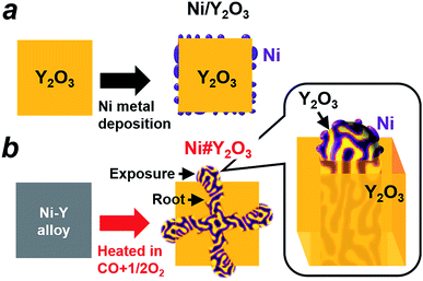
The preparation processes for different metal/oxide catalysts are shown in Fig. 1. Traditional supported catalysts including Ni/Y2O3 and Ni/Al2O3 were prepared by a routine impregnation method (Fig. 1a; see the ESI† for details). The Ni#Y2O3 catalyst was obtained from a Ni–Y (Ni![[thin space (1/6-em)]](https://www.rsc.org/images/entities/char_2009.gif) :
:![[thin space (1/6-em)]](https://www.rsc.org/images/entities/char_2009.gif) Y = 1
Y = 1![[thin space (1/6-em)]](https://www.rsc.org/images/entities/char_2009.gif) :
:![[thin space (1/6-em)]](https://www.rsc.org/images/entities/char_2009.gif) 1) alloy precursor consisting of Ni metal and oxyphilic Y metal (Fig. S2†). The Ni–Y alloy was heated at 873 K in a gas mixture of CO and O2 (CO
1) alloy precursor consisting of Ni metal and oxyphilic Y metal (Fig. S2†). The Ni–Y alloy was heated at 873 K in a gas mixture of CO and O2 (CO![[thin space (1/6-em)]](https://www.rsc.org/images/entities/char_2009.gif) :
:![[thin space (1/6-em)]](https://www.rsc.org/images/entities/char_2009.gif) O2 = 2
O2 = 2![[thin space (1/6-em)]](https://www.rsc.org/images/entities/char_2009.gif) :
:![[thin space (1/6-em)]](https://www.rsc.org/images/entities/char_2009.gif) 1 in volume%; see details in the ESI†) to promote nanophase separation from a uniform alloy into a nanocomposite consisting of metal Ni and Y2O3, namely, Ni#Y2O3. The Ni#Y2O3 nanocomposite comprised an entangled network of fibrous metal Ni and Y2O3, which further sprouted out of the bulk to develop a rooted structure (Fig. 1b; see Fig. S3† for a possible formation mechanism of the rooted structure).30 As the control catalyst, different Ni–Y2O3 nanocomposites with different Ni/Y ratios of 5/1, 3/1, 2/1 and 1/3 were prepared from the corresponding Ni–Y alloy precursors (Ni5Y, Ni3Y, Ni2Y and NiY3, respectively; Fig. S4 and S5†) via the same atmospheric treatment as for the Ni#Y2O3.
1 in volume%; see details in the ESI†) to promote nanophase separation from a uniform alloy into a nanocomposite consisting of metal Ni and Y2O3, namely, Ni#Y2O3. The Ni#Y2O3 nanocomposite comprised an entangled network of fibrous metal Ni and Y2O3, which further sprouted out of the bulk to develop a rooted structure (Fig. 1b; see Fig. S3† for a possible formation mechanism of the rooted structure).30 As the control catalyst, different Ni–Y2O3 nanocomposites with different Ni/Y ratios of 5/1, 3/1, 2/1 and 1/3 were prepared from the corresponding Ni–Y alloy precursors (Ni5Y, Ni3Y, Ni2Y and NiY3, respectively; Fig. S4 and S5†) via the same atmospheric treatment as for the Ni#Y2O3.
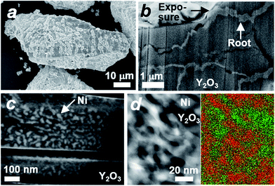
The microstructure of the Ni#Y2O3 catalyst was characterized with a scanning electron microscope (SEM). A number of precipitates were observed on the surface of the Ni#Y2O3 particles (Fig. 2a). The cross-section SEM images demonstrated that the precipitates arose from the exposure of a rooted structure that propagated from the bulk to the surface (Fig. 2b). High-magnification SEM and STEM observations further showed that the rooted structure was composed of fibrous Ni- and Y2O3 phases (Fig. 2c and d, see also Fig. 1b and S6–S8†).
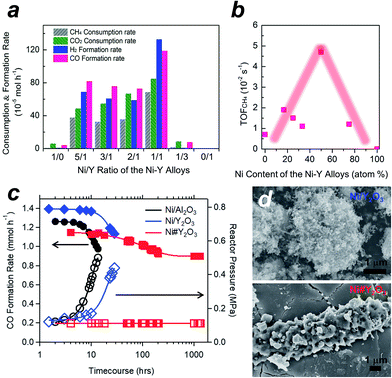
We tested the Ni#Y2O3 catalyst for LT-DRM in comparison to the other Ni-based catalysts prepared from different alloy precursors (Fig. 3a, see the corresponding SEM images in Fig. S5†). Pure Ni-powder exhibited very low activity, due to the low dispersion degree of the active Ni sites (Table S1 and Fig. S9†). The different Ni–Y2O3 composites also exhibited lower consumption- and formation rates than the Ni#Y2O3 catalyst. This should be attributed to the overgrowth of Ni or Y2O3 during the atmospheric processing of CO/O2 (Fig. S5 and S9†). The CH4- and CO2 consumption rates over the Ni#Y2O3 catalyst were close to half the value of the CO- and H2 formation rates, showing that the LT-DRM was promoted in a nearly stoichiometric pathway. We then evaluated the turnover frequency (TOF) of Ni#Y2O3 and the different Ni-based catalysts towards CH4 conversion (i.e. TOFCH4, Table S2†).31,32 The Ni#Y2O3 catalyst exhibited a much higher TOFCH4 than the other catalysts prepared from different alloy precursors (Fig. 3b). The Ni#Y2O3 catalyst was optimized in terms of composition to achieve the highest LT-DRM performance.
We finally compared the Ni#Y2O3 catalyst with traditional supported catalysts in terms of long-term stability for LT-DRM (Fig. 3c). Note that the size of the Ni sites of Ni#Y2O3 (19 nm) was close to those of the supported catalysts including Ni/Y2O3 (19 nm) and Ni/Al2O3 (22 nm) (Table S1 and Fig. S10†). However, the Ni#Y2O3 catalyst stably promoted LT-DRM at 723 K for over 1000 hours, keeping the reactor pressure constant. A slight drop during the first 100 hours was observed, likely because the catalyst needed an initiation to reach a balance of carbon deposition and re-oxidation. In contrast, the traditional supported catalysts such as Ni/Al2O3 and Ni/Y2O3 showed rapid lowering in CO formation although they exhibited superior catalytic activity in the early stages.
A similar trend was also observed in dense gas conditions (Fig. S11;† catalyst amount = 0.1 g; reaction temperature = 823 K; CH4/CO2/N2 = 10/10/5 in vol%; flow rate = 25 mL min−1). The initial CH4- and CO2 conversions in LT-DRM were 49% and 38% over the supported Ni/Al2O3 catalyst, respectively, but rapidly decreased down to 12% and 9.1% after 10 h. However, our Ni#Y2O3 catalyst initially exhibited 12% and 20% for the CH4- and CO2 conversions, respectively, and kept them higher than 7.5% and 14% even at a time course of 100 h. The reactor pressure containing the supported catalysts increased as the conversion rates decreased, which was a typical trend observed when the reactor is clogged by carbon deposits (Fig. 3c and the inset in Fig. S11†). In addition, a higher TOFCH4 was exhibited by the supported catalysts (Table S2†), but the carbon balance was much larger than unity (i.e. [CH4 consumption rate + CO2 consumption rate]/CO formation rate > 1.0; see Table S3† and the caption). The provided carbon species of CH4 and/or CO2 were more readily converted into carbon deposits than CO over the supported catalysts. Unlike the supported catalysts, Ni#Y2O3 exhibited a unity of carbon balance to achieve full conversion of CH4 and CO2 into CO without carbon deposits.
In order to elucidate the origin of the carbon-deposition tolerance of Ni#Y2O3, we performed different characterizations of the catalysts that were exposed to the LT-DRM atmosphere for 6 h (see Fig. S12† for pXRD). SEM observation showed that the supported Ni/Al2O3 as well as Ni/Y2O3 were heavily covered with fibrous deposits (Fig. 3d and S13†). The Ni#Y2O3 catalyst was free from fibrous deposits, instead it was thinly coated with a deposit layer (Fig. 3d and S14†). Raman analyses demonstrated that this deposited layer consisted of disordered and deficient carbon species (Fig. S15 and Table S4†).33,34 In addition, hard X-ray photoemission spectroscopy (HAXPES: Fig. S16†) and thermogravimetry (TG: Fig. S17†) showed that the total amount of carbon deposits on the Ni#Y2O3 catalyst was less than that on the Ni/Al2O3- or Ni/Y2O3 catalysts.
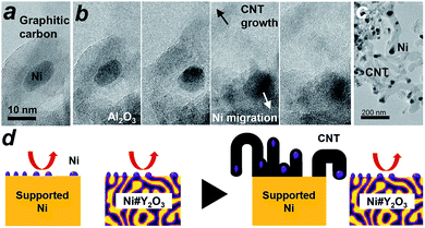
We then conducted in situ TEM to shed light on the growth dynamics of the fibrous carbon in the LT-DRM atmosphere. The Ni/Al2O3 catalyst was exposed to a reactant gas consisting of equimolar CH4 and CO2 at 723 K with a pressure of 200 Pa, and observed with high-voltage in situ TEM (JEM-1000K RS TEM (JEOL), Nagoya Univ.). In an aliquot taken 2 h after the exposure to the reactant gas, an onion-shell pattern from graphitic carbon was clearly recognized all the way around the supported Ni nanoparticles (Fig. 4a). A series of in situ TEM snapshots show that this graphitic carbon layer was decomposed near at the Ni/Al2O3 interface, most likely by oxygen species donated from the Al2O3 support (Fig. 4b, see Movie S1†). The Ni nanoparticle in the field of view migrated away from the center to the bottom right through the missing part of the graphitic carbon layer.
Fig. 4b also shows that a rapid growth of hollow, multi-walled carbon nanotubes (CNT) was triggered by the migration of Ni nanoparticles. It is acknowledged that Ni nanoparticles, when they are able to freely migrate around without a support, play the role of an efficient catalyst that promotes the growth of long-length CNT fibres from gaseous carbon species such as ethanol vapour via a vapour–solid (VS) mechanism.35–37 The carbon species provided from the gaseous atmosphere are dissolved in the Ni bulk and recrystallize on the surface in the form of a CNT, which further grows along with the drift of the migrating nanoparticles. As a result of collective migration of the Ni nanoparticles, the Ni/Al2O3 and Ni/Y2O3 catalysts were densely covered with large numbers of CNTs (50 nm and 500 nm in average thickness and length, respectively; Fig. 4c, S13 and S18†) after exposure to the LT-DRM atmosphere for 6 h. Note that each of the grown CNT contained one Ni nanoparticle at one end as the growth front.
By contrast to the supported Ni nanoparticles, the Ni catalyst centre of Ni#Y2O3 is topologically immobilized due to entanglement with its Y2O3 counterpart, which can preclude particle migration and the accompanying CNT growth (Fig. 4d, see Fig. S19†). Moreover, the HAXPES results on the Ni 2p and O 1s regions showed that the Ni phase of Ni#Y2O3 was retained as metal in the LT-DRM atmosphere, whereas the Ni phase of Ni/Y2O3 or Ni/Al2O3 was oxidized and/or carburized by CO2 and/or CH4 (Fig. S20 and S21†). The HAXPES spectra in the Y 3d region demonstrated that the Y2O3 phase of Ni#Y2O3, unlike that of Ni/Y2O3, contained abundant oxygen vacancies (Fig. S22 and S23†).38–40 The oxygen-deficient Y2O3 of Ni#Y2O3 not only topologically immobilizes the Ni catalysis centre, but also may contribute to the elimination of carbon deposits via atomic exchange at the Ni–Y2O3 interface. In addition, the carbon deposits formed on the catalysis centre of Ni#Y2O3 can be more readily oxidized than CNT or graphitic carbon because of their disordered and deficient nature (Fig. S15 and Table S4†).1,41 Therefore, the rooted Ni#Y2O3 catalyst, due to its topological advantages and the synergistic function with the oxygen-deficient Y2O3, successfully inhibited carbon deposition and improved reaction stability.
Conclusions
In conclusion, we present a catalyst design strategy that involves alloy preparations coupled with atmospheric processing to promote the spontaneous formation of nanocomposites consisting of entangled networks of metal and oxides. By tuning the composition of alloy precursors and the processing atmosphere, we have successfully built a composite catalyst with a rooted nanostructure, namely, Ni#Y2O3. The Ni#Y2O3 catalyst realized an improved activity and long-term stability to LT-DRM. In situ microscopic observations demonstrated that the carbon deposition occurring on traditional supported catalysts is attributable to the collective migration of metal nanoparticles. The catalysis centre of the Ni#Y2O3 is topologically immobilized by its oxygen-deficient Y2O3 counterpart to preclude particle migration and inhibit carbon deposition. Finally, the material design strategy of rooted catalysts reported here is not limited to the specific conversion of methane, but can be used for a broad range of practical applications, in which stable yet active metal/non-metal interfaces play a central role in performance, such as electrode catalysts for fuel cells and/or secondary batteries.42,43Conflicts of interest
There are no conflicts to declare.Acknowledgements
This work was preliminarily supported by the JST CREST program (grant No. JPMJCR15P1) and the JST PRESTO program towards “Innovative Catalysts”. We acknowledge support from the Advanced Characterization Nanotechnology Platform of the High Voltage Electron Microscope Laboratory of Nagoya University. This work was carried out by utilizing the facility of NIMS TEM Station and was supported by the Global Research Center for Environment and Energy based on Nanomaterials Science. The HAXPES measurements were performed under the approval of the NIMS Synchrotron X-ray Station (Proposal No. 2015B4605, 2016A4607, 2016B4600, 2017A4602, 2017B4605, 2018A4600). The authors wish to thank Dr Iida, Mr Takeda and Ms Nohara for their persistent assistance and/or fruitful discussions to accomplish this work.Notes and references
- D. Pakhare and J. Spivey, Chem. Soc. Rev., 2014, 43, 7813–7837 RSC.
- L. Shi, G. H. Yang, K. Tao, Y. Yoneyama, Y. S. Tan and N. Tsubaki, Acc. Chem. Res., 2013, 46, 1838–1847 CrossRef CAS PubMed.
- S. Li and J. Gong, Chem. Soc. Rev., 2014, 43, 7245–7256 RSC.
- J. W. Han, C. Kim, J. S. Park and H. Lee, ChemSusChem, 2014, 7, 451–456 CrossRef CAS PubMed.
- D. San-José-Alonso, J. Juan-Juan, M. J. Illán-Gómez and M. C. Román-Martínez, Appl. Catal., A, 2009, 371, 54–59 CrossRef.
- M.-S. Fan, A. Z. Abdullah and S. Bhatia, Appl. Catal., B, 2010, 100, 365–377 CrossRef CAS.
- J. R. Rostrupnielsen and J. B. Hansen, J. Catal., 1993, 144, 38–49 CrossRef CAS.
- S. Wang, G. Q. Lu and G. J. Millar, Energy Fuels, 1996, 10, 896–904 CrossRef CAS.
- A. M. Gadalla and B. Bower, Chem. Eng. Sci., 1988, 43, 3049–3062 CrossRef CAS.
- S. C. Tsang, J. B. Claridge and M. L. H. Green, Catal. Today, 1995, 23, 3–15 CrossRef CAS.
- A. W. Budiman, S. H. Song, T. S. Chang, C. H. Shin and M. J. Choi, Catal. Surv. Asia, 2012, 16, 183–197 CrossRef CAS.
- S. M. Kim, P. M. Abdala, T. Margossian, D. Hosseini, L. Foppa, A. Armutlulu, W. V. Beek, A. Comas-Vives, C. Copéret and C. R. Müller, J. Am. Chem. Soc., 2017, 139, 1937–1949 CrossRef CAS PubMed.
- T. Margossian, K. Larmier, S. M. Kim, F. Krumeich, A. Fedorov, P. Chen, C. R. Müller and C. Copéret, J. Am. Chem. Soc., 2017, 139, 6919–6927 CrossRef CAS PubMed.
- Z. Liu, D. C. Grinter, P. G. Lustemberg, T. D. Nguyen-Phan, Y. Zhou, S. Luo, I. Waluyo, E. J. Crumlin, D. J. Stacchiola, J. Zhou, J. C. Carrasco, H. B. Busnengo, M. V. Ganduglia-Pirovano, S. D. Senanayake and J. A. Rodriguez, Angew. Chem., Int. Ed., 2016, 55, 7455–7459 CrossRef CAS PubMed.
- Y. H. Hu and E. Ruckenstein, Adv. Catal., 2004, 48, 297–345 CAS.
- Y. H. Hu and E. Ruckenstein, Catal. Rev., 2002, 44, 423–453 CrossRef CAS.
- D. Pakhare, C. Shaw, D. Haynes, D. Shekhawat and J. Spivey, J. CO2 Util., 2013, 1, 37–42 CrossRef CAS.
- Y. Kathiraser, U. Oemar, E. T. Saw, Z. Li and S. Kawi, Chem. Eng. J., 2015, 278, 62–78 CrossRef CAS.
- S. Das, J. Ashok, Z. Bian, N. Dewangan, M. H. Wai, Y. Du, A. Borgna, K. Hidajat and S. Kawi, Appl. Catal., B, 2018, 230, 220–236 CrossRef CAS.
- Y. Kathiraser, W. Thitsartarn, K. Sutthiumporn and S. Kawi, J. Phys. Chem. C, 2013, 117, 8120–8130 CrossRef CAS.
- Z. Li, M. Li, Z. Bian, Y. Kathiraser and S. Kawi, Appl. Catal., B, 2016, 188, 324–341 CrossRef CAS.
- Z. Li, S. Das, P. Hongmanorom, N. Dewangan, M. H. Wai and S. Kawi, Catal. Sci. Technol., 2018, 8, 2763–2778 RSC.
- Z. Li and S. Kawi, Catal. Sci. Technol., 2018, 8, 1915–1922 RSC.
- Z. Li, Z. Wang, B. Jiang and S. Kawi, Catal. Sci. Technol., 2018, 8, 3363–3371 RSC.
- Z. Li, Y. Kathiraser and S. Kawi, ChemCatChem, 2015, 7, 160–168 CrossRef CAS.
- Z. Li, Y. Kathiraser, J. Ashok, U. Oemar and S. Kawi, Langmuir, 2014, 30, 14694–14705 CrossRef CAS PubMed.
- Z. Li, L. Mo, Y. Kathiraser and S. Kawi, ACS Catal., 2014, 4, 1526–1536 CrossRef CAS.
- Z. Li, B. Jiang, Z. Wang and S. Kawi, J. CO2 Util., 2018, 27, 238–246 CrossRef CAS.
- Z. Li and S. Kawi, ChemCatChem, 2018, 10, 2994–3001 CrossRef CAS.
- T. Tanabe, T. Imai, T. Tokunaga, S. Arai, Y. Yamamoto, S. Ueda, G. V. Ramesh, S. Nagao, H. Hirata, S. Matsumoto, T. Fujita and H. Abe, Chem. Sci., 2017, 8, 3374–3378 RSC.
- M. F. Mark and W. F. Maier, J. Catal., 1996, 164, 122–130 CrossRef CAS.
- G. L. Bezemer, J. H. Bitter, H. P. Kuipers, H. Oosterbeek, J. E. Holewijn, X. D. Xu, F. Kapteijn, A. Jos van Dillen and K. P. de Jong, J. Am. Chem. Soc., 2006, 128, 3956–3964 CrossRef CAS PubMed.
- A. C. Ferrari and J. Robertson, Phys. Rev. B: Condens. Matter Mater. Phys., 2000, 61, 14095–14107 CrossRef CAS.
- M. A. Pimenta, G. Dresselhaus, M. S. Dresselhaus, L. G. Cancado, A. Jorio and R. Saito, Phys. Chem. Chem. Phys., 2007, 9, 1276–1290 RSC.
- R. T. K. Baker, M. A. Barber, P. S. Harris, F. S. Feates and R. J. Waite, J. Catal., 1972, 26, 51–62 CrossRef CAS.
- R. T. Yang and J. P. Chen, J. Catal., 1989, 115, 52–64 CrossRef CAS.
- J.-P. Tessonnier and D. S. Su, ChemSusChem, 2011, 4, 824–847 CrossRef CAS PubMed.
- G. B. Sun, K. Hidajat, X. S. Wu and S. Kawi, Appl. Catal., B, 2008, 81, 303–312 CrossRef CAS.
- P. Malacrida, H. G. S. Casalongue, F. Masini, S. Kaya, P. Hernández-Fernández, D. Deiana, H. Ogasawara, I. E. L. Stephens, A. Nilsson and I. Chorkendorff, Phys. Chem. Chem. Phys., 2015, 17, 28121–28128 RSC.
- X. Huang, G. Xue, C. Wang, N. Zhao, N. Sun, W. Wei and Y. Sun, Catal. Sci. Technol., 2016, 6, 449–459 RSC.
- P. Ferreira-Aparicio, M. Fernandez-Garcia, A. Guerrero-Ruiz and I. Rodríguez-Ramos, J. Catal., 2000, 190, 296–308 CrossRef CAS.
- W. Wang, C. Su, Y. Wu, R. Ran and Z. Shao, Chem. Rev., 2013, 113, 8104–8151 CrossRef CAS PubMed.
- M. R. Palacin, Chem. Soc. Rev., 2009, 38, 2565–2575 RSC.
Footnote |
| † Electronic supplementary information (ESI) available: Demonstration procedure; experimental and characterization details. See DOI: 10.1039/c8sc04965c |
| This journal is © The Royal Society of Chemistry 2019 |


