
 Open Access Article
 This Open Access Article is licensed under a
 Creative Commons Attribution 3.0 Unported Licence
Operation range extension via hot-spot control for catalytic CO2 methanation reactors†
Jens
Bremer
 *a and
Kai
Sundmacher
ab
*a and
Kai
Sundmacher
ab
aMax Planck Institute for Dynamics of Complex Technical Systems, Sandtorstraße 1, 39106 Magdeburg, Germany. E-mail: bremerj@mpi-magdeburg.mpg.de; Tel: +49 391 6110 412
bOtto-von-Guericke University, Universitätsplatz 2, 39106 Magdeburg, Germany. E-mail: kai.sundmacher@ovgu.de; sundmacher@mpi-magdeburg.mpg.de
First published on 10th April 2019
Abstract
Heterogeneous catalytic reactions are essential for future CO2-based process routes, but are, however, sensitive to dynamic perturbations. To incorporate these processes into existing production networks, increased flexibility under different operating loads is necessary. One prominent example of a CO2-based process is methanation using H2 as a basis of the Power-to-X production concept. However, this reaction is strongly exothermic creating a major bottleneck for dynamic operation due to the limited thermal resistance of the catalyst. Based on a detailed mathematical reactor model at the industrial-scale, we found that stabilizing control is a very promising yet unexploited heat management approach. We applied stabilizing control to moderate the reactive zone (hot spot) via adaptive coolant temperature variations and compared its performance to other well-established approaches such as intensified and recycle reactors. In this way, we attained unconventional operating points in regions of steady-state multiplicity that offer reduced catalyst temperatures (<500 °C) while maintaining elevated reactor performance. When considering these additional operating points, a broader and more flexible operation of industrial reactors becomes feasible. Systematic sensitivity studies regarding relevant reactor and operating parameters indicate that a robust technical implementation of these operating points is possible.
1 Introduction
For more than 50 years, the large variety of different applications for catalytic fixed-bed reactors reported in the literature has been fueling an increasing interest in improving their performance and reliability.1–3 So far, the major aim has been to guarantee steady, safe, and efficient operations leading to a desired product quality. However, these objectives might be mutually exclusive due to complex reaction mechanisms (selectivity), thermodynamics (equilibrium) or thermal restrictions for the catalyst. For instance, when dealing with exothermic reactions, distinct heat releases must be inhibited, which often leads to lower productivities. Switching to alternative reactor designs, tailored for the specific application, has been one option to bypass certain contradicting objectives. Therefore, typical designs that have been developed are, e.g., fluidized-bed reactors, wall-coated reactors, membrane reactors, slurry reactors, or microstructured reactors. More advanced designs correspond to the so-called integrated or multi-functional reactor concepts.4–6 They attempt to realize an optimal reaction route by incorporating optimal fluxes for heat and mass directly at the reaction site. Still, most of these concepts and designs are made for steady operation (except for batch processes), which may not reveal their full performance potential.7,8Further benefits might be obtained when unsteady operations are taken into consideration. In fact, the trend towards a more flexible production to react to markets as well as to volatile inputs (e.g., coming from renewable sources) in particular requires unsteady and more flexible process operation, in which catalytic reactors play a key role as outlined in Fig. 1. Buffers might be able to harmonize the volatility to a limited extent. Kalz et al.9 recently highlighted in detail the conceptional importance of future catalytic systems under dynamic reaction conditions and concluded that this research direction is still underrepresented in the literature, especially for synthesis of chemical energy carriers. Earlier studies in this area are mainly focusing on the catalytic material, surface and structure under dynamic conditions. Nevertheless, the dynamic behavior of reactive systems has already been investigated back in the late 60s.10–12 Even with limited computational capabilities, these investigations, often based on first principle models, built an impressive fundamental knowledge about the dynamics of reactive systems and proposed possible dynamic interaction concepts that can lead to higher reactor performance. However, the relative share of these concepts in commercial applications remains scarce due to the increased technical requirements.13 Currently, we see many new incentives driven by a more sustainable chemicals and energy carrier production, which requires one to reevaluate former achievements and adjust them to the challenges we are facing today. The present study intends to follow this idea by taking up the example of catalytic methanation as a key process for future CO2-based production chains and extending fundamental knowledge on dynamic reactor operation.
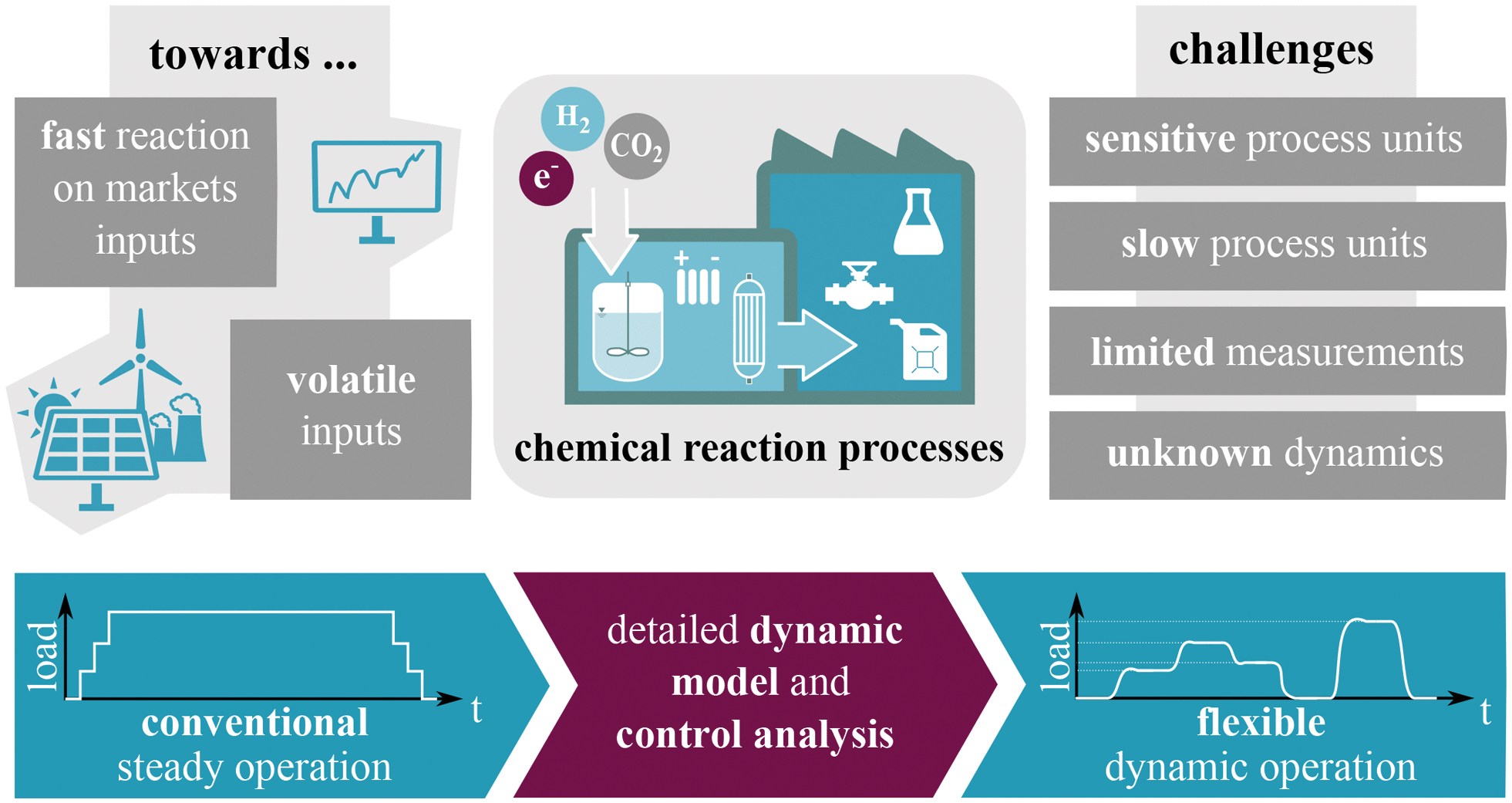 | ||
| Fig. 1 Towards more flexible processes in chemical reaction engineering. | ||
Catalytic CO2 methanation is an exothermic reaction and offers a promising route for surplus-oriented electricity storage and chemicals production based on renewable generation, e.g., wind and solar. However, due to its significant heat generation, distinct hot-spot formations occur which can strongly influence the catalyst durability and process safety. For this reason, the required heat management is one major objective of ongoing research and becomes more important in dynamic operation. A comprehensive review on methanation is provided by Rönsch et al.14
A common approach for improved heat management is to design reactor concepts with intensified heat transfer via increased surface–volume ratios between coolant and reactive sites. Typical examples broadly discussed throughout the literature are micro-reactors, honeycomb reactors, monolithic reactors, plate reactors, catalytic wall reactors.15–21 In terms of heat management, these intensified reactor concepts (see Fig. 2 left) have been proven to be superior to industrial scale tube bundle reactors. However, this advantage comes at a cost, i.a., lower throughputs and higher investment costs. A more convenient yet very promising approach for heat management during dynamic operation was proposed by Matthischke et al.22 They used the recycle reactor concept (see Fig. 2 center) in their experimental setup to effectively reduce the heat generation while increasing the reactors flexibility with respect to load changes. Nevertheless, disadvantages can appear due to the thermal and material feedback which might lead to instabilities during transient transitions. Apart from that, lower space–time-yields and additional auxiliary units also lead to economic drawbacks. A combination of optimization, heat management and dynamic operation goes back to our previous study on controlled reactors, where we presented an alternative heat management concept based on optimal transient coolant control during start-up of an industrial-scale reactor unit (see Fig. 2 right).23 Beside the classification in Fig. 2 there are many more studies on heat management, often assuming steady-state conditions. Just to mention a few, Kiewidt and Thöming24 proposed a model-based Semenov number optimization approach to compute optimal axial temperature profiles while maintaining the catalyst temperature limitation. Further optimization studies in this context, with special focus on steady operation of an entire methanation plant model, were provided by El Sibai et al.25
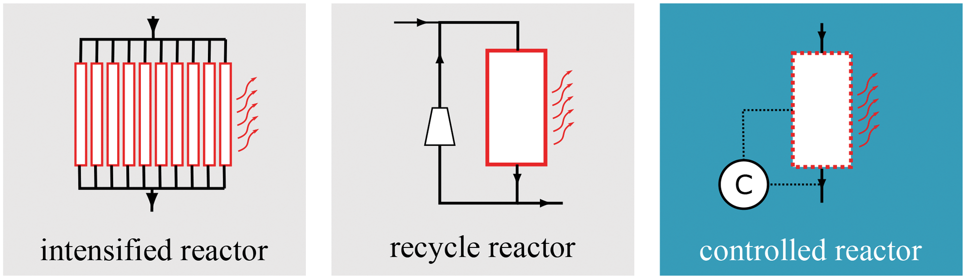 | ||
| Fig. 2 Reactor concepts for improved heat management considered in this study. | ||
In accordance with our previous work, this study aims for more fundamental explanations and a better understanding of our model-based optimization results with respect to a broader operation range, as well as technical relevance among other concepts. One major outcome is the identification of dynamically stabilized operation regimes of industrial-scale reactors, which exist due to the appearance of multiple steady-states. Making use of this often ignored operation regime requires to explore reactor dynamics and concepts for stabilizing feedback control. In addition, this regime also enables the reactor to operate in a broader load range with reduced hot-spot formation, as it is necessary to ensure long term dynamic reactor operation.
This paper is divided into four sections. Initially, we provide a brief overview of the operation ranges of cooled exothermic fixed-bed reactors and explain one possible source for range extension. Afterwards, the underlying generic reactor model is explained in detail with special focus on the extensions compared to the previous model introduced in Bremer et al.23 The final model form is motivated by previous works from Schlereth and Hinrichsen26 as well as Kiewidt and Thöming.24 Subsequently, a computational study gives new insight regarding typical operation regimes of exothermic reactors exemplified for CO2 methanation. Therefore, we test different catalytic activities, as well as different reactor designs (conventional vs. intensified reactors and product recycle/feed dilution), regarding their conversion and heat management performance. Finally, we present and thoroughly discuss the concept of stabilized coolant control and outline its relevance among conventional reactor concepts.
2 Reactor flexibility and steady-state multiplicity
Throughout this work we use the term flexibility to assess the size of the attainable reactor load (or state) with respect to certain performance values (e.g., conversion, yield, selectivity, max. bed temperature, etc.). Thus, the flexibility of a reactive system is directly correlated to the size of its attainable performance range.In addition to other investigations focusing on the dynamic transition from one stable reactor state to another,27–29 this study also searches for states only accessible via transient interaction (e.g., closed-loop control). These further on denoted as unstable states, are often encapsulated within operation regimes characterized by steady-state multiplicity12 which abolishes the uniqueness between a steady-state and its corresponding operational setting (e.g., inlet or coolant temperature). Despite the pervasive opinion to avoid such unstable operation regimes in practical applications,30 we refer to the pioneering work of Eigenberger and Schuler,31 who stated that
… instability is not a problem insofar as safe operation is concerned, if the unstable system reacts so slowly that it can easily be stabilized by a quick adjustment.
Consequently, the access to unstable states in a reactive system, is not per se prohibited, but rather subject to possible stabilization strategies. In order to find and to evaluate the reactor performance at these intrinsically unstable states, we propose to initially search for regions of steady-state multiplicity.
In general, steady-state multiplicity boils down to the existence of systematic feedback.32 Therefore, a steady-state in a reactive system is always strongly determined by its former conditions (memory effect). In this context, we differentiate between “intrinsic” and “extrinsic” feedback. Intrinsic feedback can be associated with the complexity of the underlying reaction mechanisms or flow regimes. Analytical criteria for steady-state multiplicity and uniqueness related to the reaction mechanism has been widely discussed in the literature.33–35 Furthermore, intrinsic feedback also arises from thermal effects such as heat conduction and accumulation, or from catalyst degradation and poisoning.32,36 In this regard, spatially distributed systems, such as fixed-bed reactors with strong exothermicities and inhibited mixing effects, are prime examples. In contrast, “extrinsic” feedback refers to externally organized coupling, e.g., reactors equipped with recycle loops coupled to other process units. Prominent examples for external feedback are autothermal reactor concepts as reviewed by Kolios et al.6 This work exclusively deals with multiple steady and unsteady states evoked by “intrinsic” thermal feedback.
Catalytic CO2 methanation generates a significant amount of heat and, thus, causes in particular “intrinsic” thermal feedback, which determines the attainable operation regime, i.e. with respect to inlet flow rate, inlet temperature, coolant temperature, coolant flow rate. Although this study mainly focuses on manipulating the coolant temperature, the proposed methodology can be easily adapted to further parameters. Furthermore, the reactor performance in this work is evaluated with respect to CO2 conversion X and the highest temperature within the catalytic bed Tmax. A qualitative illustration of typical operation regimes evoked by variation of the coolant temperature is shown in Fig. 3.
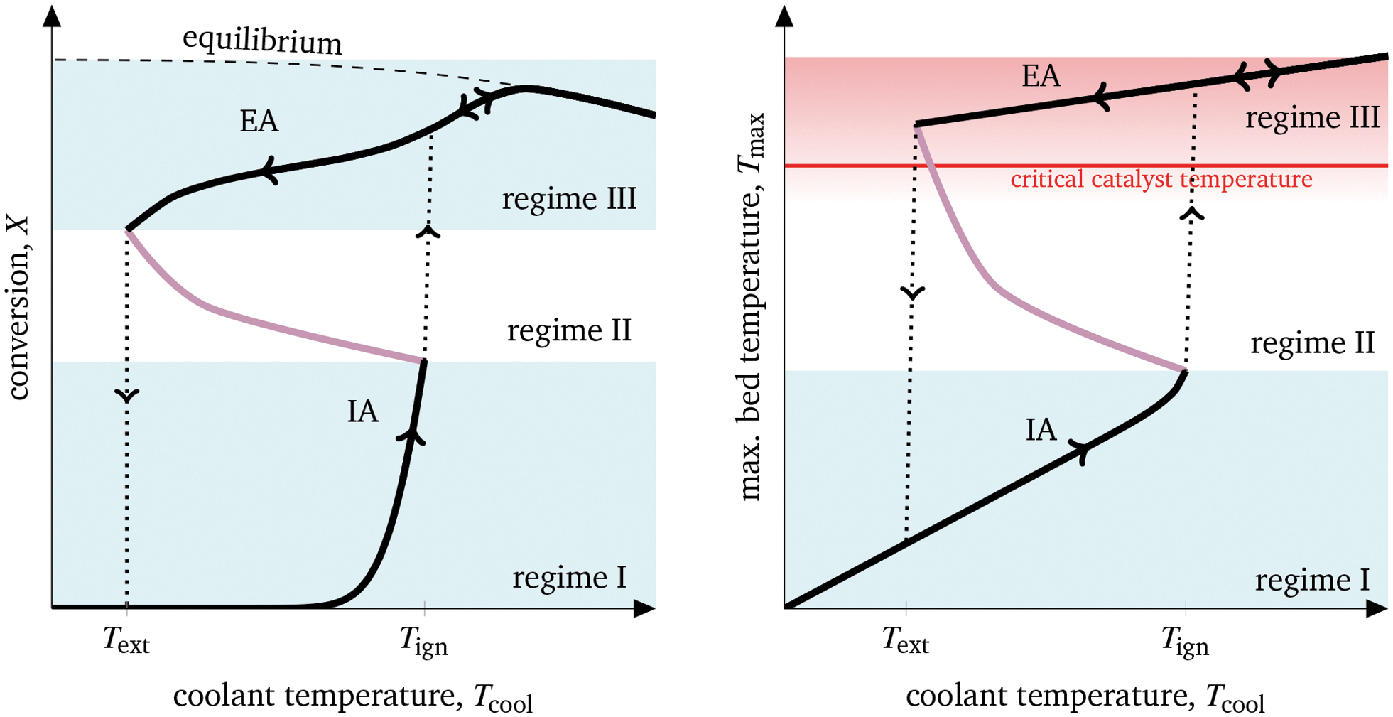 | ||
| Fig. 3 Characteristic operation arcs and operating regimes of cooled exothermic fixed-bed reactors exemplified for CO2 methanation. | ||
Two characteristic operation arcs can be observed in Fig. 3: the ignition arc (IA) and the extinction arc (EA). The IA is attainable by means of coolant temperature increase starting with a non-ignited reactor (regime I), whereas the EA is attainable by means of coolant temperature decrease starting with an ignited reactor (regime III). In fact, the IA is widely used in kinetic studies to compare the activity of different catalytic systems or rate expressions.21,37 Accordingly, for one specific reactor set-up with fixed gas residence time, the catalyst is considered to be more active, if the required temperature for reaching the thermodynamic equilibrium is lower. The IA yields an ignition temperature Tign that is strongly influenced by the reactor dimensions and operation conditions.26 As a result, there is a coolant temperature range in which small variations lead to significant state changes, often referred to as parametric sensitivity.38 Thus, it is not recommended to operate in this region to avoid thermal runaways. This also applies to the in literature less mentioned EA and its corresponding extinction temperature Text. Together, IA and EA form a hysteresis curve evoked by the aforementioned “intrinsic” thermal feedbacks in which both multiple steady states (black arcs in regime I and II) and also unstable states (purple arc in regime II) are present. Although the existence of unstable states is widely discussed and underpinned by bifurcation analyses for various applications,39–41 so far very little attention has been given to the question how to make use or even operate at these states. Nevertheless, enabling reactors to operate within unstable regimes would significantly widen its conventional operation range (only regime I and III). This becomes interesting when the catalyst degrades at higher temperatures, preventing operation within the highly productive regime III.
To make use of the unstable regime II in Fig. 3 and to get access to additional reactor loads (e.g., with higher conversion or lower bed temperatures), a concept for transient interaction is vital. So far, two major concepts have been established in the literature: forced-periodic operation and stabilizing control.
• Forced-periodic operation goes back to Horn and Lin10 and covers flow direction switches, e.g., simulated moving beds chromatographic reactors42 or reactor switches,13,43 as well as periodical input and environment manipulation.44,45 Further comprehensive overviews are given by Bunimovich et al.7 and Hudgins et al.46 Even for methanation this approach is recently considered.47,48
• Stabilizing control for chemical reactors was already mentioned in the pioneering work of Aris and Amundson.49 The authors introduced and analyzed in depth the influence of proportional temperature control to the stability of exothermic continuously stirred tank reactors (CSTR). Building upon this, Viel et al.50 further elaborated control schemes for global CSTR stabilization including possible input constrains. Other studies focused on reactor control aspects such as robustness, uncertainties, Kalman filters, state observer, and optimal control.51–55
Forced-periodic operation is not the objective of this work as it is continuously stressing process units and actuators which often leads to serious doubts in its technical feasibility and scale-up potential.13 Instead, process control is an essential and already implemented component of many technical applications, such that the realization of stabilizing control requires just little effort in comparison to its achievable process improvements. For this reason, we select the concept of stabilizing control to obtain access to the above outlined region of unstable states.
The CSTR represents a very prominent example for stabilizing control due to its small number of system equations. However, this work aims to apply stabilizing control to plug flow tubular reactor (PFTR) types. The challenge here results from a much larger set of system equations (due to the spatial distribution of mass and energy), strong nonlinearities, and the desire to represent an industrial relevant reaction mechanism. Since PFTRs can be seen as a series of several CSTRs, similarities might be also available with respect to their dynamic behavior. To date, detailed elaborations in this direction are still insufficiently represented in the literature. In order to fill this gap, we will introduce an exemplary tubular reactor model for CO2 methanation in the following section which will be the basis for subsequent simulation and control studies.
3 Dynamic reactor modeling
Our study is based on a pseudo-homogeneous model for fixed-bed reactors exemplified by CO2 methanation. This strongly exothermic reactionCO2 + 4H2⇌CH4 + 2H2O, ΔR![[H with combining tilde]](https://www.rsc.org/images/entities/i_char_0048_0303.gif) 0 = −164.9 kJ mol−1, 0 = −164.9 kJ mol−1, | (1) |
| CO + 3H2⇌CH4 + H2O, ΔR0 = −206.3 kJ mol−1, | (2) |
| CO2 + H2⇌CO + H2O, ΔR0 = 41.1 kJ mol−1. | (3) |
However, CO formation is not favored at elevated pressures and mean bed temperatures below 750 K. A more detailed analysis of thermodynamic limitations is comprehensively illustrated by Gao et al.62 Regarding kinetic limitations induced by the catalytic system, this work mainly relies on a recent study of Koschany et al.,37 but also considers an older, more often referred to study by Xu and Froment.63 Both studies consider nickel-based catalysts, but the latter exhibits a significantly lower activity for carbon dioxide methanation, since it was performed with a steam methane reforming (SMR) catalyst, whereas Koschany et al.37 refer to a state-of-the-art methanation catalyst. However, this high activity is opposed by lower thermal resistance – a major technical problem for methanation14 and important aspect in this study.
To explore the internal reactor temperature, steady-state multiplicity and its behavior under different dynamic scenarios, we expand our previously reported dynamic pseudo-homogeneous model23 by intraparticle transport limitations (via temperature dependent effectiveness factors), state-of-the-art kinetics, variable gas phase velocity, axial dispersion, and a more profound coolant heat transport resistance. Fig. 4 illustrates the used single-tube fixed-bed reactor model with all considered levels.
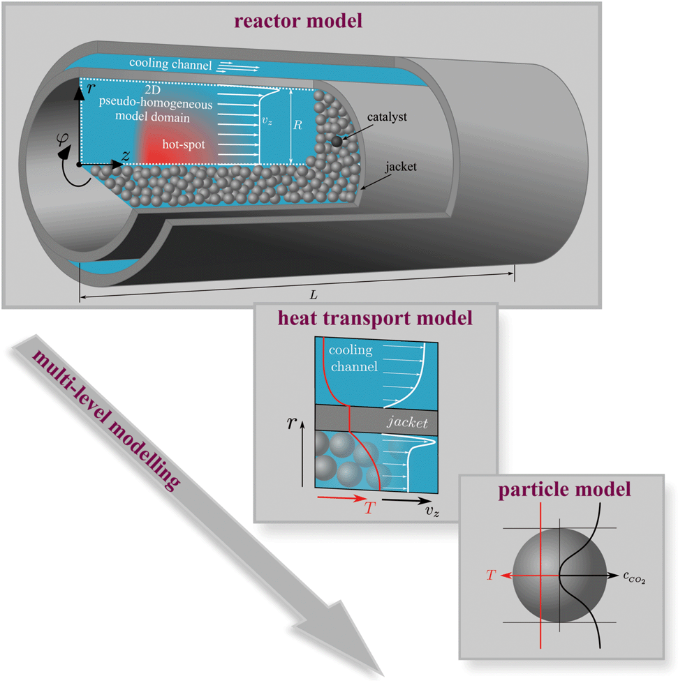 | ||
| Fig. 4 Illustration of the fixed-bed reactor model. | ||
The governing equations of mass and energy conservation are derived from the Eulerian specification of an arbitrary reactor volume element and lead to the partial differential equation (PDE) system:
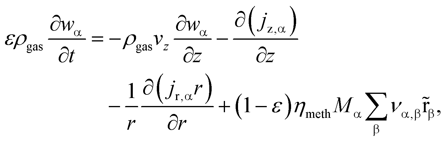 | (4) |
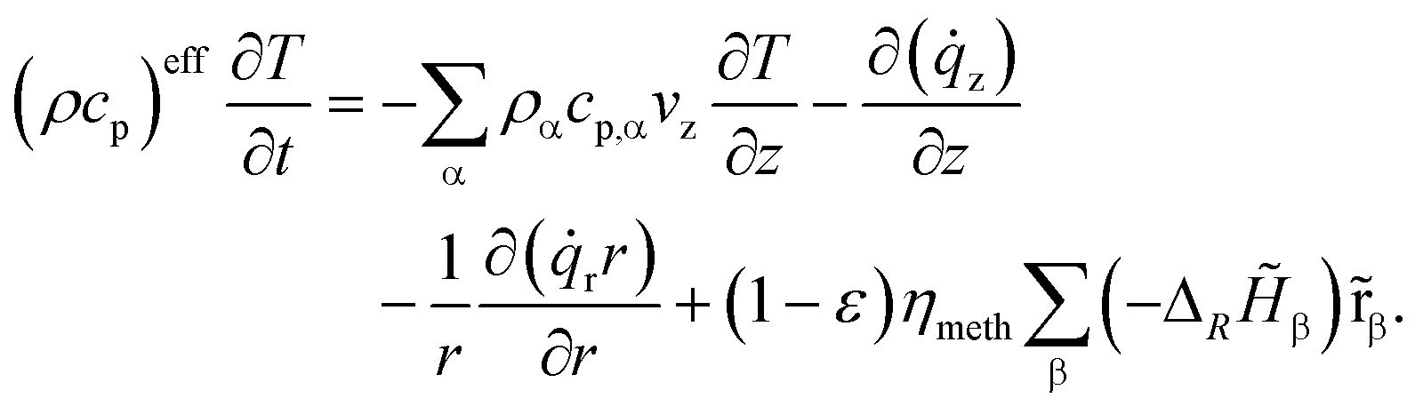 | (5) |
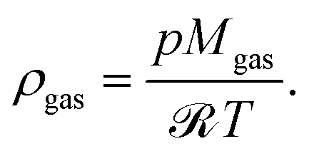
As part of our assumptions, all components α ∈ {CH4, CO, CO2, H2O, H2, N2} and reactions β on the catalyst side are jointly considered in a pseudo-homogeneous phase. In accordance with the criterion 2R/dp > 10 plug-flow behavior with negligible flow-induced wall effects is assumed for the gas phase.64 Furthermore, we avoid calculating the dynamic momentum balance, since it is well known that this introduces effects with significantly lower time constants, which easily lead to higher numerical stiffness of the dynamic system and thus to much higher computational effort.27 Instead, our model considers gas velocity changes exclusively due to mass conservation. As the overall axial mass flow remains constant, the following equation holds:
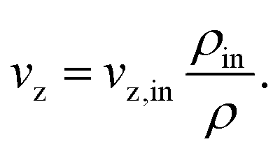 | (6) |
At this point, we would like to mention that some studies consider the concentration ratio in eqn (6) instead of the density ratio.30,47 However, only the mass flux remains constant, since the total number of molecules is not a conservative quantity.
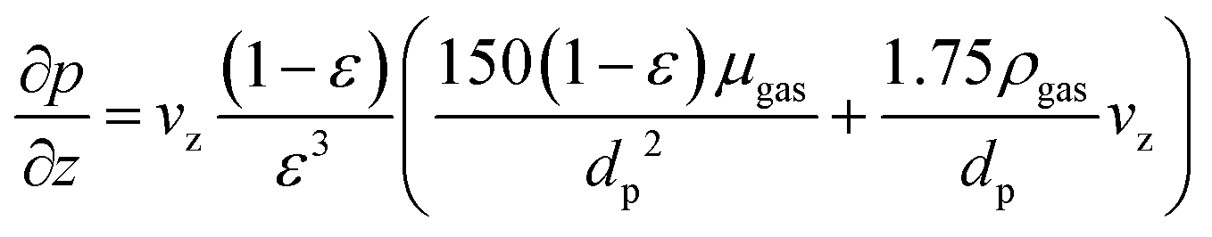
With regard to pressure changes, we follow the assumption that the dynamic momentum balance of a fixed-bed is typically dominated by friction, allowing us to rely on the Ergun equation to compute the corresponding pressure drop:
 | (7) |
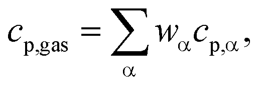
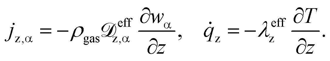
Further correlations in eqn (5) are dedicated to the effective volumetric heat capacity
| (ρcp)eff = (1 − ε)ρcatcp,cat + ερgascp,gas, |
To solve eqn (4) and (5), we expand our two-dimensional model domain illustrated in Fig. 4 (top) in axial direction by nonreactive, adiabatic subdomains of length γ before and behind the catalytic bed. This ensures all Neumann boundary conditions (necessary for axial mass and energy dispersion terms) to be zero at the reactors inlet and outlet. At r = R and z = −γ further boundary conditions hold:
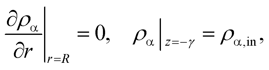 | (8) |
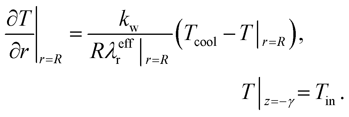 | (9) |
Furthermore, initial conditions at t = 0 are set according to the dynamic case (e.g., start-up, disturbance, step change), respectively.
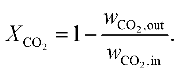
Our single reactor tube in Fig. 4 can be considered as part of a typical industrial-scale bundle configuration. The tube design as well as reference operational parameters are summarized in Table 1 and the corresponding reactor states and characteristics are given in the ESI.† The major performance parameter used in this study are bed temperature and CO2 conversion. The latter is defined as
| Inner reactor radius | R | = | 0.01 | m | |
| Reactor length | L | = | 2.5 | m | |
| Wall thickness | δ jac | = | 0.002 | m | |
| Wall thermal conductivity | λ jac | = | 20 | W m−1 K−1 | Stainless steel |
| Fixed-bed void fraction | ε | = | 0.4 | ||
| Catalyst particle diameter | d p | = | 0.002 | m | |
| Catalyst density | ρ cat (porous material) | = | 2355.2 | kg m−3 | 63 |
| Catalyst specific heat capacity | c p,cat (nonporous material) | = | 1107 | J kg−1 K−1 | 65 |
| Catalyst emissivity | ε cat | = | 0.9 | ||
| Catalyst thermal conductivity | λ cat | = | 3.6 | W m−1 K−1 | 21, 66 |
| Catalyst tortuosity | τ p | = | 2 | ||
| Catalyst porosity | ε p | = | 0.6 | ||
| Catalyst pore diameter | d pore | = | 10 | nm | |
| Superficial velocity | v z | = | 1 | m s−1 | |
| Inlet pressure | p in | = | 5 | bar | |
| Inlet temperature | T in | = | 300 | K | |
| Inlet molar ratio | H2![[thin space (1/6-em)]](https://www.rsc.org/images/entities/char_2009.gif) :CO2 :CO2 |
= | 4:1 |
(Undiluted) | |
| Coolant heat transfer coefficient | α cool | = | 500 | W m−2 K−1 | ESI |
| Gas hourly space velocity | GHSV (STP based) | = | 7200 | h−1 | |
| Overall heat removal |

|
= | 1.7 | kW | |
| Reaction kinetics | 37 |
3.1 Reaction kinetics
This model deals with two different kinetic models for nickel-promoted CO2 methanation: from Koschany et al.37 (very active, but thermally sensitive) and Xu and Froment63 (less active, but thermally less sensitive). The consideration of both studies allows a better comparability and placement among former research.24,26 However, the reference kinetic model for most of the results presented in this study, are based on the work of Koschany et al.37 due to the recent trend towards specialized methanation catalysts. In addition, the usage of two different kinetic approaches can be also seen as a variation of the catalyst activity, which is closely related to possible catalyst degradation influences (e.g. due to long-term operation).The reference kinetic model (w/o particle transport limitations) from Koschany et al.37 relies on a Langmuir–Hinshelwood Hougen–Watson (LHHW) type rate equation, measured and parameterized for a broad range of conditions (453–613 K; 1–9 bar; stoichiometric and non-stoichiometric feed).
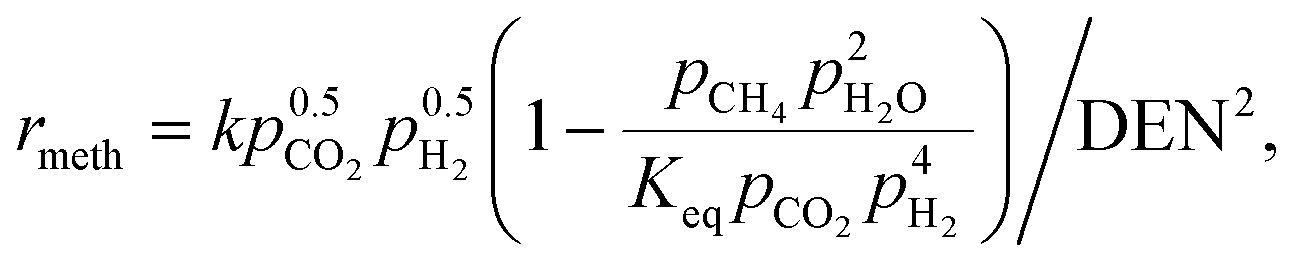 | (10) |
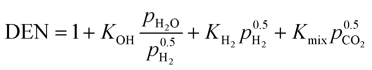 | (11) |
Although this rate equation is determined for a limited temperature range, its usage out of it is definitely valid. For higher temperatures, the reaction rates are limited by the chemical equilibrium (thermodynamically limited) and at lower temperatures the reaction rates approach zero (kinetically limited). The important temperature range is right between these two limiting cases and accordingly covered by Koschany et al.37 Further details on all relevant correlations necessary to implement eqn (10) and (11) are outlined in the ESI.† There, more details on the rate equations according to Xu and Froment63 can also be found.
3.2 Mass and heat transport assumptions
 | (12) |
 | (13) |
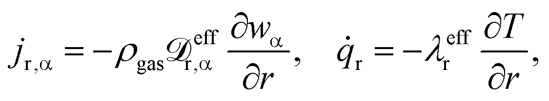
Details regarding the radial dispersion coefficients in eqn (12) are given in our previous work.23 In addition, this study also discusses possible axial effects viaeqn (13) and evaluates their relevance for exothermic fixed-bed reactors.
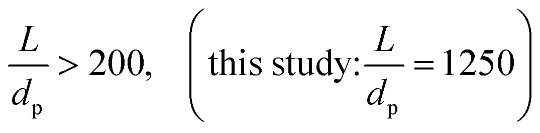
The relevance of axial mass dispersion in relation to axial mass convection in a fixed-bed can be evaluated with the Bodenstein number
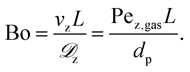
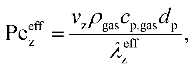
For Bo > 100 axial convective mass transport dominates significantly and mass dispersion (i.e. axial back-mixing) becomes negligible.64,67 Furthermore, for high particle Reynolds numbers (Rep > 10 – typical for catalytic reactors of industrial scale as considered in this study) the axial Péclet number converges to a constant value: Pez,gas → 2.68–70 Consequently, while operating within the criteria
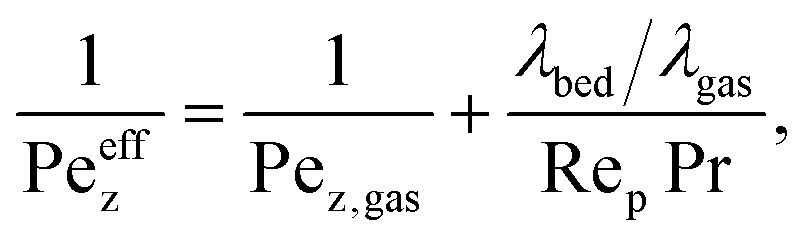
In terms of axial heat dispersion, the criterion given above is not directly adaptable. According to Dixon and Cresswell,71 for large 2R/dp ratios one can rely on
 | (14) |
Some studies report a stabilization effect for their numerical solution schemes when axial dispersion is considered within the model.47 Such an observation was not explicitly confirmed by this study, which might be explained by the high dimensionality (time and two spatial dimensions) of our model. Taking an additional physical effect (e.g. dispersion) into account primarily increases the computational load, which might not be sufficiently compensated by its stabilization benefit.
 | (15) |
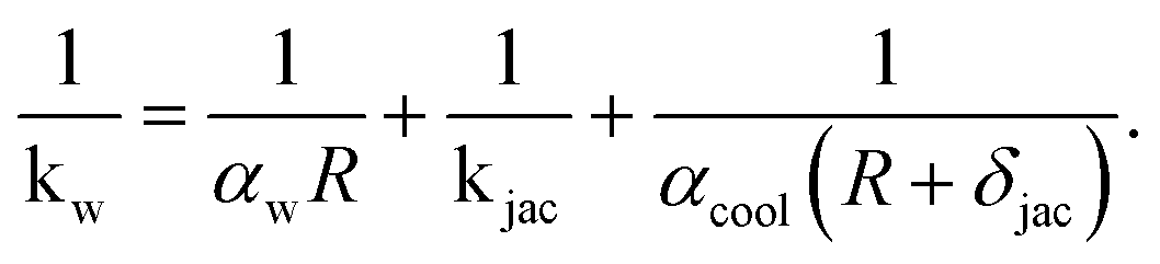
Details regarding αw, kjac, and αcool are given in the ESI.† There we conclude that the coolant heat transfer αcool represents the limiting resistance which is simply a result of our coolant selection (thermal oil). According to our derived coolant Nusselt number range (see ESI†), the heat transfer coefficient in Table 1 of αcool = 500 W m−2 K−1 is reasonable, but approximately four times lower as reported in other studies.26,29,74 Higher values are certainly attainable when steam is used as heat transfer medium. However, in section 4.2 we show that a limited coolant heat transfer is, in fact, favorable to widen the reactor operation range via stabilizing control.
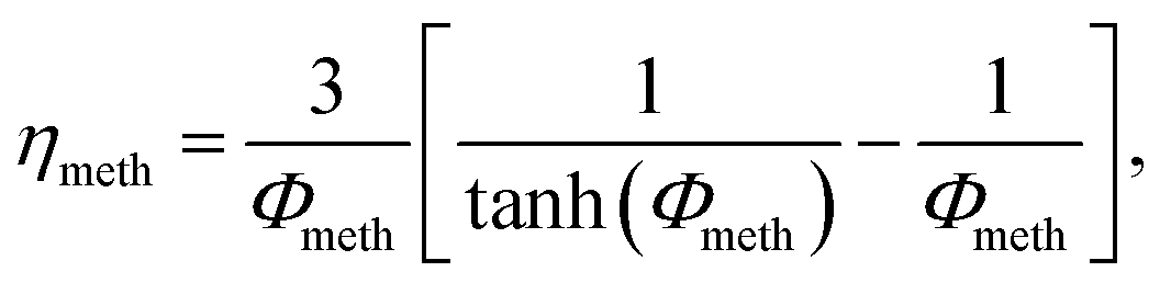
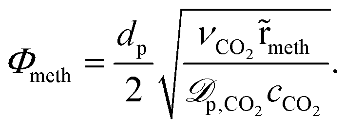
In order to account for temperature dependent intra-particle mass transport limitations in combination with the pseudo-homogeneous phase assumption, Kiewidt and Thöming24 proposed to use an effectiveness factor based on the Thiele modulus for spherical particles
 | (16) |
 | (17) |
Therefore, the effective diffusivity inside the particle ![[scr D, script letter D]](https://www.rsc.org/images/entities/char_e523.gif) p accounts for molecular m and Knudsen diffusion Knvia
p accounts for molecular m and Knudsen diffusion Knvia
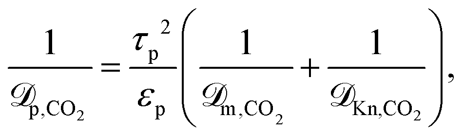 | (18) |
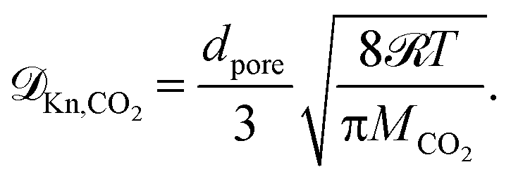 | (19) |
Eqn (18) and (19) also account for the catalyst consistency characterized by the particle porosity εp and tortuosity τp, as well as the average pore diameter dpore. The molecular diffusion m is calculated via the Wilke–Chang equation for multicomponent gas mixtures.75
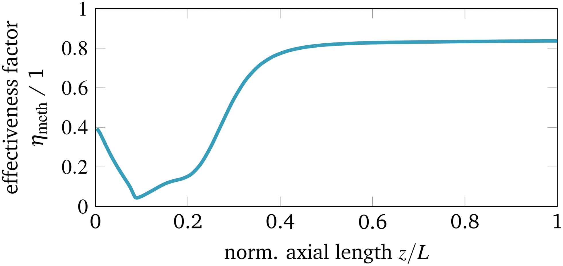
This approach is certainly restricted due to the selection of one key component (here CO2) and the application to an equilibrium limited reaction. Recently, Kiewidt21 presented an extended and more accurate approach for general reaction rate forms as initially proposed by Bischoff.76 Still, the strong exothermicity might also cause distinct temperature gradients inside the catalyst particle, which can result in an effectiveness factor above one. However, for our case studies we observed that the effectiveness factor along the reactor axis (see Fig. 5) stays below one which is in accordance to the results presented by Schlereth and Hinrichsen26 (heterogeneous model) and Kiewidt and Thöming24 (pseudo-homogeneous model).
3.3 Computational aspects
In order to discretize and solve the reactor model as described by eqn (4) and (5) a finite volume (FV) scheme is used. Due to the wide operation range considered in this study, a relatively high mesh resolution of 12 FVs in radial and 150 FVs in axial direction was found to be sufficient for all seven PDEs (counting for six mass fractions and one temperature). Further meshing details can be taken from the ESI.† Consequently, the spatially discretized PDE system leads to 12 × 150 × 7 = 12600 differential states, i.e.x ∈ ![[Doublestruck R]](https://www.rsc.org/images/entities/i_char_e175.gif) 12600. In addition, further algebraic states z ∈ 150 are required to account for the pressure drop in axial direction, such that the entire reactor model is represented as the following nonlinear time-invariant system of differential algebraic equations (DAEs):
12600. In addition, further algebraic states z ∈ 150 are required to account for the pressure drop in axial direction, such that the entire reactor model is represented as the following nonlinear time-invariant system of differential algebraic equations (DAEs):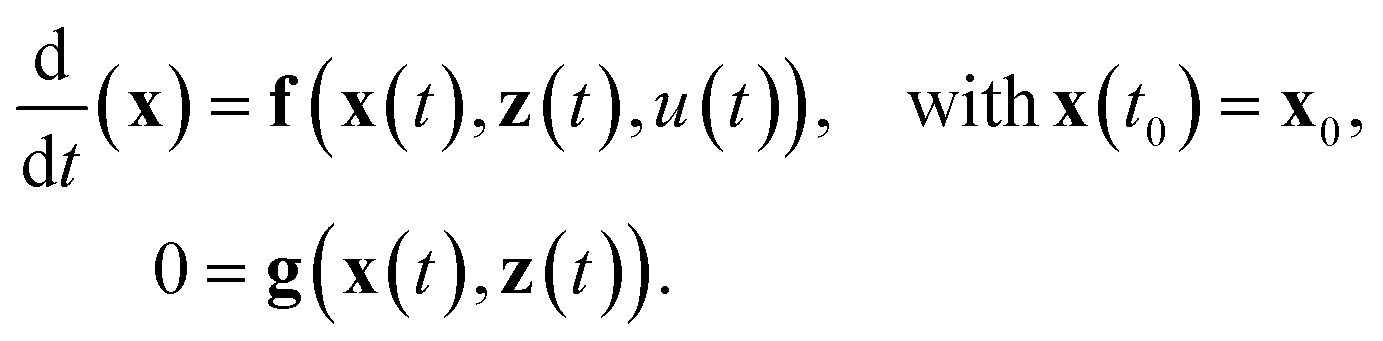 | (20) |
Most of the underlying physical correlations and properties from above are given explicitly and do not appear as additional algebraic equations. Only the reactor pressure, calculated according to the Ergun equation, is given implicitly via the velocity and, thus, via the differential states (see eqn (6)). The scalar control u ∈ 1 solely refers to the temperature of the cooling fluid Tcool. Based on this dynamic model, the transient reactor behavior induced by any coolant temperature perturbation (constant or time variant) can be simulated from each initial state x0 (e.g., for an ignited or non-ignited reactor). Thus, the broad operation range of such systems becomes easily accessible by well developed integrators. Therefore, we make use of CasADi v3.2.077 which allows us to interface the DAE system (20) written in MATLAB to powerful SUNDAILS integrators.78 With this set-up, we achieve CPU times between 100 and 350 seconds for one dynamic simulation of 3000 seconds reactor operation, depending on how much the reactor condition is changing during simulation. Such an effective computation is essential for extensive dynamic studies as presented in the next section.
4 Computational experiments
In order to characterize the reference reactor configuration (see Table 1) with respect to the existence of steady-state multiplicity evoked by different cooling temperatures, we perform several feed-forward simulation studies. Furthermore, we compare common strategies (intensification, product recycle/feed dilution) for improved heat management and show, how they influence the appearance of multiple operating states and the overall reactor performance.4.1 Steady-state operation
Starting with a cold reactor (gas compositions and temperatures similar to the feed condition), we increase the control u = Tcool stepwise until the thermodynamic equilibrium is reached. Each step is a dynamic simulation of 3000 seconds, which is long enough to reach the new steady-state. In this way, we are able to screen the ignition arc (IA) for our reactor configuration as generally discussed in section 2. In contrast, the extinction arc (EA) is generated by stepwise reduction of the control u = Tcool, starting from an already ignited reactor, which operates close to the equilibrium line. The result of this screening for the two different activity/kinetic cases, is illustrated in Fig. 6.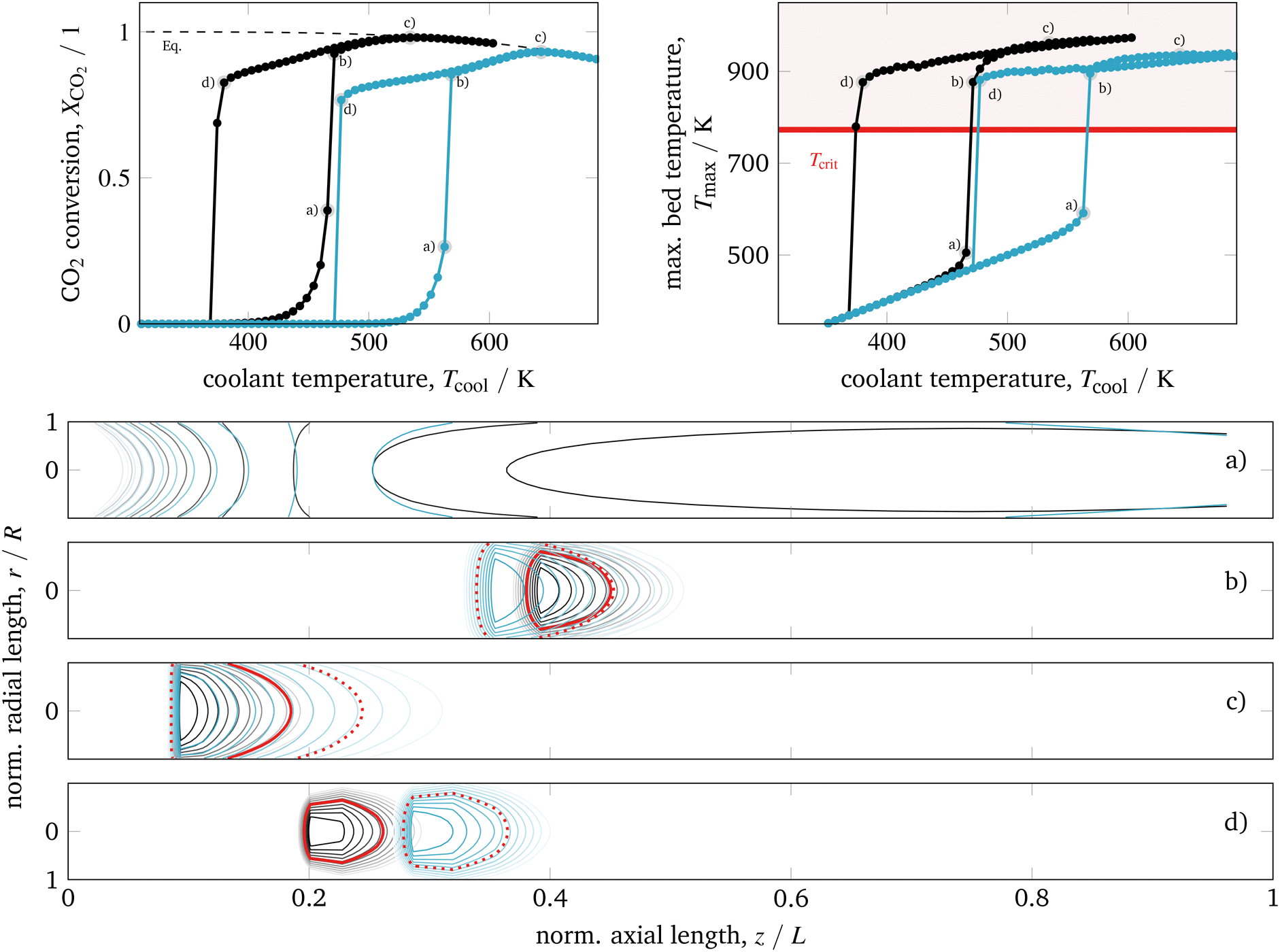 | ||
| Fig. 6 Ignition and extinction arcs for different catalyst activities with respect to CO2 conversion (top left), maximum bed temperature (top right), and spatial temperature field (bottom) – contours decrease in 2%-increments of Tmax; according to Koschany et al.37 (black); according to Xu and Froment63 (blue); for further details see animations in the ESI.† | ||
In general, we see a significant influence of the catalyst activity on the reactor performance. Compared to a highly active catalyst (black), the IA and EA of the less active catalyst (blue) are shifted towards higher coolant temperatures. Nevertheless, the highest bed temperatures Tmax are reduced due to lower CO2 conversions caused by the chemical equilibrium. On the contrary, highly active methanation catalysts often suffer from a lower thermal resistance, such that during operation a critical catalyst temperature (typically Tcrit = 775 K) must not be exceeded.14,79 Furthermore, both catalysts evoke a similar spread between ignition and extinction temperature (hysteresis width), which indicates that this characteristic is barely influenced by the catalyst activity itself.
Looking at the temperature field in Fig. 6 (bottom) reveals the stationary hot-spot position regarding the coolant temperature. Following the IA by starting with low coolant temperatures, the non-ignited reactor behaves very similar to a heat exchanger. Towards the reactor outlet, the cold inlet gas is heated up until it reaches the coolant temperature (coolant acts as heater). A further increase of the coolant temperature leads to broad regions of elevated temperatures slightly above the coolant temperature, caused by a mild heat release of the exothermic reaction (state a). When the ignition temperature is reached, the heat release starts to exceed the heat removal and accumulates in the reactor center (r = 0). As a consequence, the temperature in the reactor center increases significantly (runaway) until the difference between reactor and coolant temperature is large enough to sufficiently remove the heat by the coolant. Thus, a distinct hot-spot is formed – for low inlet temperatures approximately in the middle of the reactor (state b). As long as the catalyst is able to tolerate these temperatures, kinetic limitations are reduced and yield higher conversions. When the coolant temperature is increased further, the hot-spot moves towards the reactor inlet and higher conversions are achieved until thermodynamic limitations become dominant and lower the CO2 conversion (state c).
To exploit the EA in Fig. 6, we decrease the coolant temperature starting from an already ignited reactor (state c). Until state b) is reached, there is almost no difference in conversion and highest bed temperature between EA and IA. Nevertheless, the hot-spot is not exactly restored in accordance to the IA. Instead, the high temperatures of the former steady-states are still “memorized” and lead to stretched hot-spot shapes, more closely located to the inlet. As a result, the ongoing heat release is able to keep the reaction running even for lower coolant temperatures and steeper radial temperature gradients as associated with state b) of the IA. However, as the heat removal becomes more dominant for lower coolant temperatures, the hot-spot extinction is induced approximately 100 K below the ignition temperature. Moreover, the hot-spot extinction occurs closer to the inlet than its former ignition. In addition, Fig. 6 illustrates that higher catalyst activities tend to sharper, more concentrated hot-spots with different locations, especially on the EA.
The operation close to a) – for non-ignited reactors – and d) – for ignited reactors – is very sensitive to changes in the cooling temperature. This phenomenon is well known as parametric sensitivity,38 and many authors suggest to avoid an operation close to or in between these states due to stability and safety restrictions. However, we have seen that an operation on a distinct EA – not too close to d) – has a clear potential for stable operation when lower cooling temperatures and high conversions are required.
In order to validate the accuracy of our model, two key characteristics are of major importance: the highest bed temperature and the ignition temperature (runaway temperature). Although both characteristics can be found in various studies, a comparison is often rather limited due to the influence of the respective reactor design and operation case. Very close to our model set-up and considering the less active catalyst case, Schlereth and Hinrichsen26 have shown detailed simulation studies in very good agreement to our IA results in Fig. 6 (blue), such that our highest bed temperature of above 900 K and the ignition temperature slightly below 570 K can be confirmed. As a third key characteristic, we propose to address the extinction temperature due to its pronounced dependence on the chosen heat transfer characteristics. Unfortunately, no reliable data to validate our results regarding this third key characteristic could be found in the literature so far.
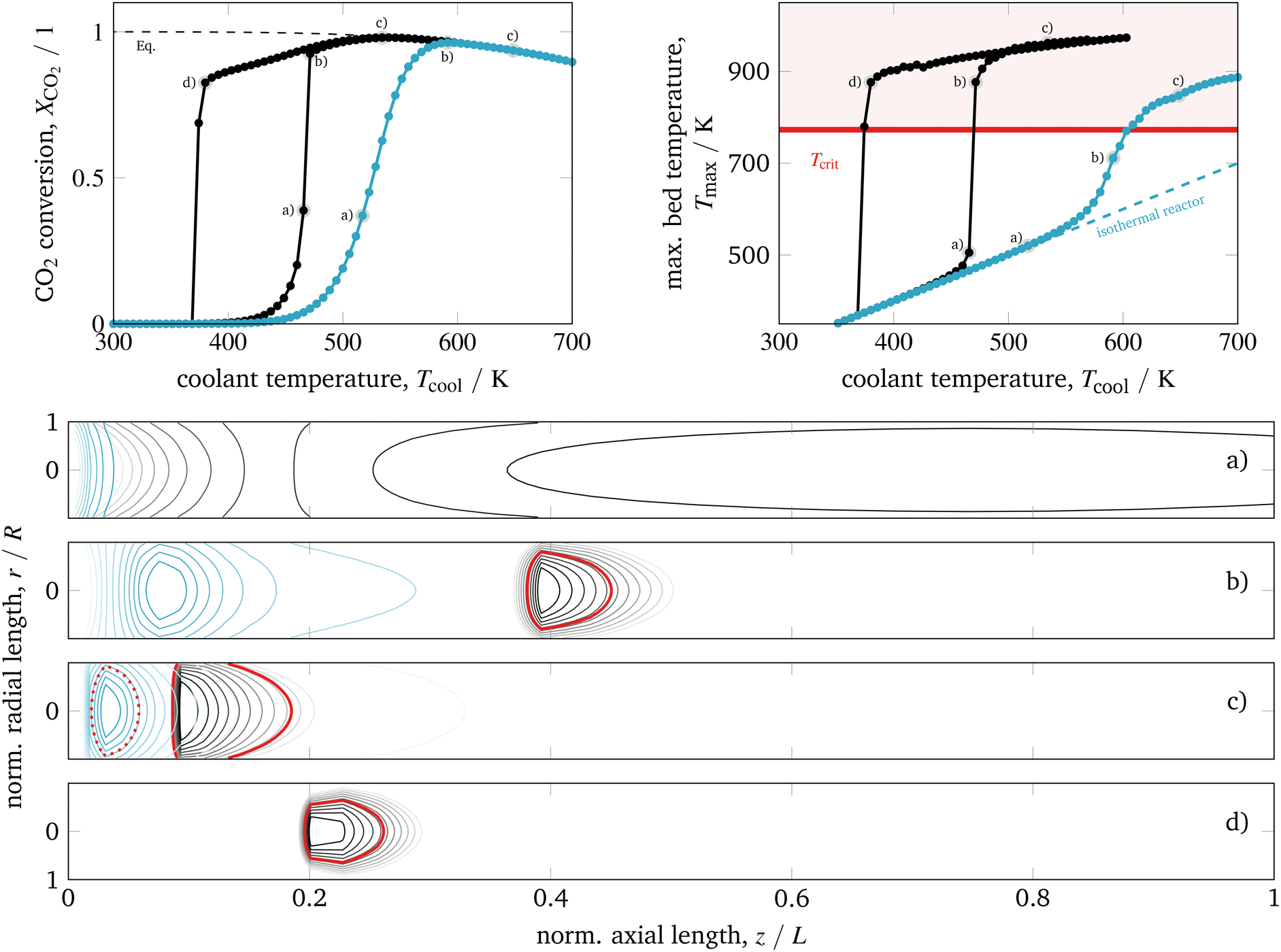 | ||
| Fig. 7 Ignition and extinction arcs of reference case (black) in comparison to intensified reactors (blue – L/10, R/10, dpart/10) with respect to CO2 conversion (top left), maximum bed temperature (top right), and spatial temperature field (bottom) – contours decrease in 2%-increments of Tmax; for further details see animations in the ESI.† | ||
Apparently an improved heat removal eliminates the existence of multiple steady-states with respect to the coolant temperature. In contrast, a lower heat removal (e.g., due to larger reactor dimensions) can yield broader regions of multiple steady-states. Thus, the reactor dimension and coolant heat transfer are key parameters that influence the reactor's steady-state multiplicity.
For the intensified case (blue) in Fig. 7, the IA and EA coincide and distinct ignitions are smoothed out (but still present compared to the limiting case of an isothermal reactor). In addition, at states of high conversion the bed temperature is relatively low and more equally distributed, even for the more active catalyst. Thus, intensified reactors are reasonable alternatives to improve heat management and to deal with possible temperature limitations of the catalytic system. Regarding dynamic considerations, Fig. 7 shows that intensified reactors are much less sensitive with respect to changes of the coolant temperature (reduced parametric sensitivity). Consequently, a possible reactor runaway due to load changes or disturbances is less likely. Furthermore, smaller reactor volumes with less thermal mass are favored to perform fast reactor start-up or load changes and, thus, allow for more flexible reactor operation. For this reason, intensified reactors are currently the topic of many research activities.15–20 However, hot-spots might still appear in regimes of elevated coolant temperatures, where thermodynamic limitations are already pronounced. Disadvantages often include high pressure drop, high investment cost, and channel blockage. One further disadvantage that we would like to outline here is related to the enhanced coolant temperatures (approx. +150 K for case b in Fig. 7), which can cause technical restrictions for the right coolant selection (see section 4.2.2).
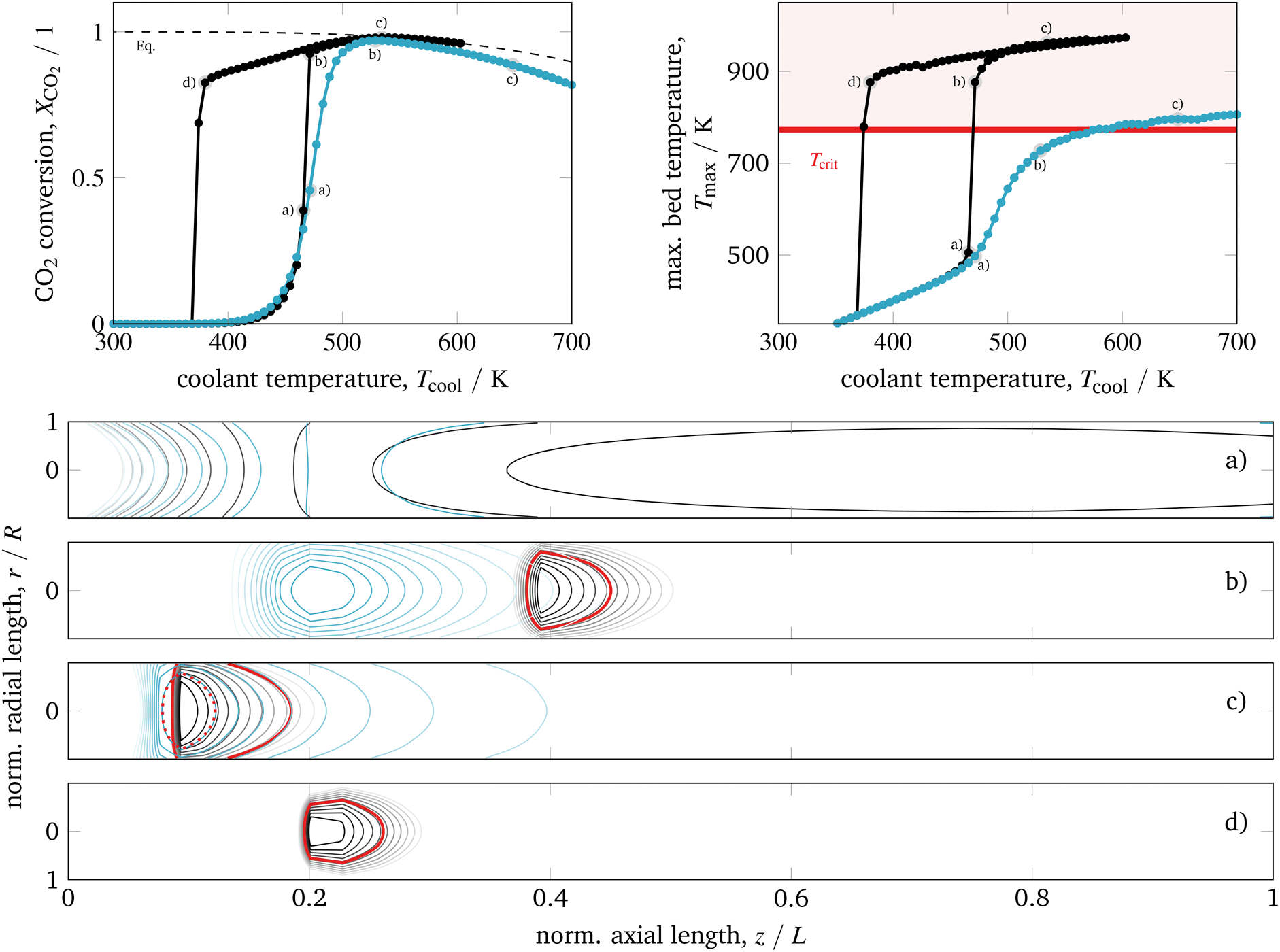 | ||
| Fig. 8 Ignition and extinction arcs of reference case (black) in comparison to 40% product recycle (blue) with respect to CO2 conversion (top left), maximum bed temperature (top right), and spatial temperature field (bottom) – contours decrease in 2%-increments of Tmax; for further details see animations in the ESI.† | ||
Similar to intensified reactors, the mitigated heat generation eliminates the appearance of cooling related multiple-steady states. High conversion and tolerable bed temperatures are achieved, although the reactor dimensions correspond to the reference case. Another advantage compared to intensified reactors is given due to lower coolant temperatures (similar to the reference case) when operating in high conversion regimes. Consequently, dilution and product recycle are very promising strategies to improve heat management and often considered in methanation studies.22,58,74,80
Nevertheless, product recycle always requires additional auxiliary units (e.g., compressors, heat exchangers) and reduces the reactor space–time yield, whereas feed dilution increases the downstream separation load. In both cases, investment costs will certainly increase. In addition, the dynamic behavior of reactors with product recycle often suffers from transient oscillations during load changes and especially during start-up procedures. Apart from that, a permanent recycling can also lead to an accumulation of contaminants harming the catalyst (e.g., sulfur components). If theses reactor types are intended to be used very flexibly in a broad operation range, a deeper understanding of the respective dynamics is essential as addressed by ongoing research activities.22
4.2 Stabilized operation
In contrast to the open-loop simulations discussed above, this section deals with transient variations of the coolant temperature. The relevance of this approach to control the internal heat generation was shown via rigorous optimization studies by Bremer et al.23 Here, we aim for more fundamental explanations and a better understanding of these optimization results with respect to a broader operation range and its technical relevance.In order to allow for transient cooling temperature variations without the expensive computation of optimization studies, we couple the reactor model with a PI-controller (see Fig. 9) of the following structure
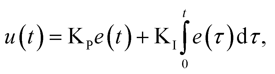 | (21) |
 | (22) |
 and not for different cooling temperatures. Furthermore, the simulation procedure in this section is initialized with a steady-state on the EA from which the conversion set-point is reduced stepwise always after reaching a new steady-state. The result of this procedure in comparison to the former open-loop simulations is illustrated in Fig. 10.
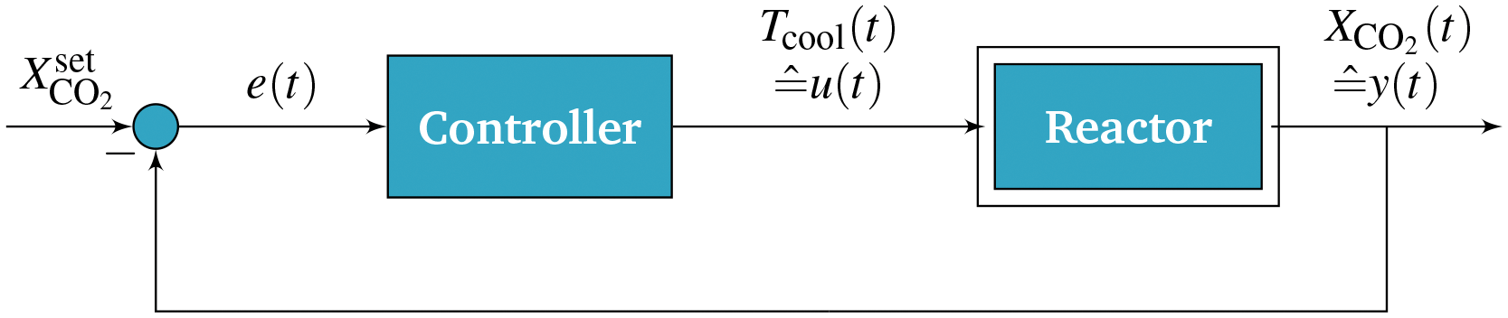 | ||
| Fig. 9 Closed-loop scheme for reactor control. | ||
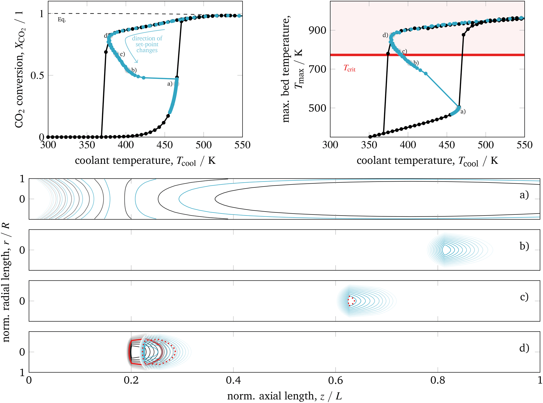 | ||
| Fig. 10 Ignition and extinction arcs of reference case (black) in comparison to stabilized operation via PI-control (blue) with respect to CO2 conversion (top left), maximum bed temperature (top right), and spatial temperature field (bottom) – contours decrease in 2%-increments of Tmax; for further details see animations in the ESI.† | ||
The first closed-loop simulations with activated PI-controller (blue) are converging to the same EA steady-states as obtained with the open-loop simulations (black). The cooling temperature variations induced by the controller can be also interpreted as disturbances around the EA steady-states, which proves a certain stability of the EA. However, more important is the observed behavior after passing the state d) and approaching conversion set-points close to the former extinction point. Due to the activated controller, a further reduction of the conversion set-point does not lead to an extinction, as observed in the open-loop case. Instead, a new arc becomes attainable between the EA and the IA. Deactivating the controller in this domain after steady-state is reached leads the reactor back to a steady-state either on the EA or on the IA. Consequently, these new steady-states are open-loop unstable, but closed-loop stable. Although the existence of multiple unstable states within the hysteresis loop is already mentioned in various studies,36,81–85 we figured out that their stabilization at technical relevant conditions is indeed possible for controlled fixed-bed reactors.
In order to explain the stabilization effect, the thermal mass/inertia of the catalytic bed is of major importance. As a result of the distinct heat capacity and density of the solid particles, any bed temperature change (due to the chemical reaction or due to cooling changes) is delayed. This effect is incorporated in our model via the accumulation term in eqn (5). As long as the controller manipulates the cooling temperature faster than the time delay coming from the heat accumulation, a stabilization of the reaction zone becomes feasible. More details on the open-loop and closed-loop stability and potential technical limitations are given in sections 4.2.1 and 4.2.2.
From these observations, three major advantages of this control approach can be derived:
• Controlled exothermic fixed-bed reactors of common dimension can be operated in a much broader operation regime (denoted as regime II in Fig. 3).
• The new operation regime involves reduced bed temperatures which can prevent catalysts from thermal degradation.
• Due to the proven controllability, a flexible reactor operation with regard to load or set-point changes is possible.
Looking at the temperature field in Fig. 10 shows that during our closed-loop simulations the reactive zone moves towards the outlet. Similar to the explanations regarding the existence of the EA, the actual condition/position of the reaction zone is again strongly influenced by its former condition/position. Finally, the stabilized arc in Fig. 10 (blue) collapses once the reactive zone has reached the end of the reactor. A further reduction of the conversion set-point brings the reactor to the IA.
Several parameter studies are conducted in order to better comprehend the stabilized steady-states. We found that the cooling intensity, the reactor pressure, as well as the particle diameter to be of major importance. These parameter studies are also chosen to demonstrate that the stabilized states are not just result of a specific reactor configuration, but rather a characteristic feature of any exothermic fixed-bed reactor.
Since the cooling can be also manipulated via the coolant flow rate, which directly influences the cooling heat transfer coefficient αcool, Fig. 11 illustrates this parameter influence corresponding to higher and lower cooling rates.
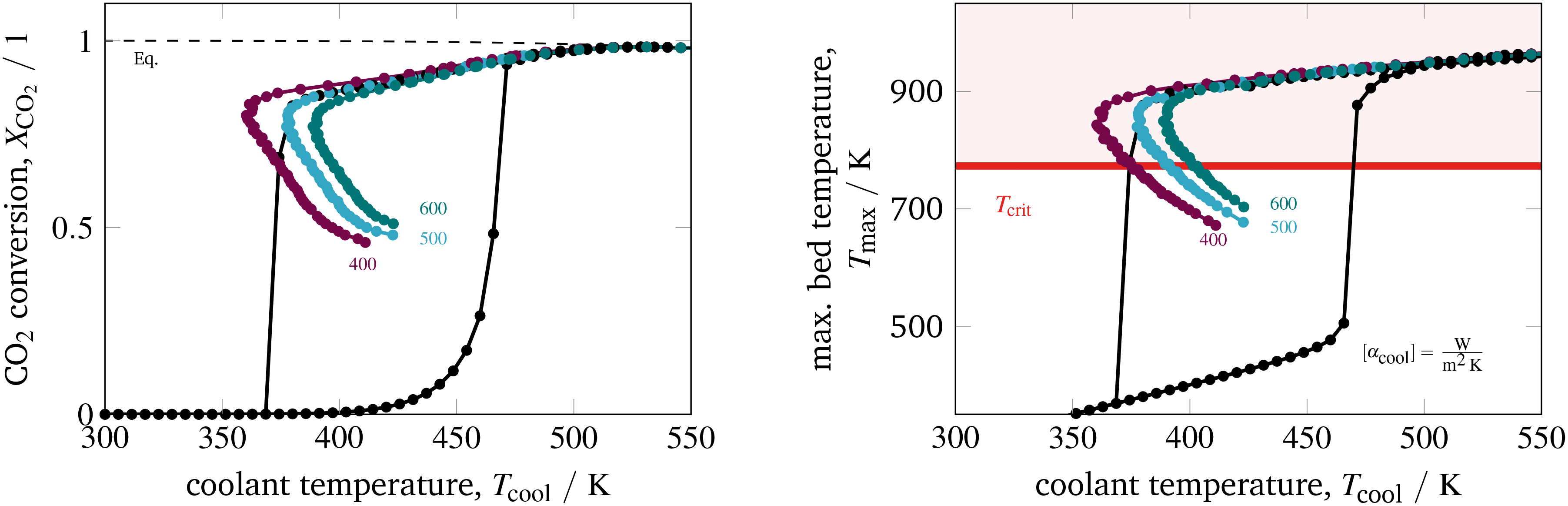 | ||
| Fig. 11 Stabilized operation regime for varying coolant heat transfer, reference model set-up: controlled (colored) and uncontrolled (black). | ||
Accordingly, under intensified heat transfer conditions, the hysteresis loop shrinks and all states on the stabilized arc are shifted towards higher cooling temperatures. This behavior is similar to what we have seen for intensified reactors. Thus, a further intensification of the heat transfer would eliminate the hysteresis loop and any corresponding stabilized arc. On the contrary, less intensive cooling features broader hysteresis loops and broader stabilized arcs at lower cooling temperatures. Compared to an operation at higher cooling temperatures or to reactor concepts without state-space multiplicity, the coolant mass flow reveals a larger impact on the reactor performance. This observation might also allow further control actions and a more flexible operation.
The inlet pressure influences the reactor performance in several ways. On the one hand, a higher pressure intensifies the reaction, so that more heat is generated. On the other hand, a higher pressure increases the effective radial heat conduction of the catalytic bed due to higher gas densities and intensified hydrodynamics/turbulences. Fig. 12 illustrates an inlet pressure variation. In general, elevated pressures exhibit more pronounced hysteresis loops and broader stabilized arcs. The bed temperature effect emerges as quite interesting to observe. Looking at the EA for a constant cooling temperature reveals that higher pressure causes higher bed temperatures. The increased heat generation dominates the increased radial heat transfer. In contrast, the stabilized arc shows an inverse behavior. Apparently, for reduced reaction zones the increased radial heat transfer becomes dominant when the inlet pressure is increased. However, the reduced bed temperature also reduces the conversion. Nevertheless, the impact of the inlet pressure might offer further potential for additional control actions. For instance, a pressure variation in combination with our temperature control concept might be useful to allow for feed load changes (e.g., due to volatile production from renewable sources) under constant conversion.
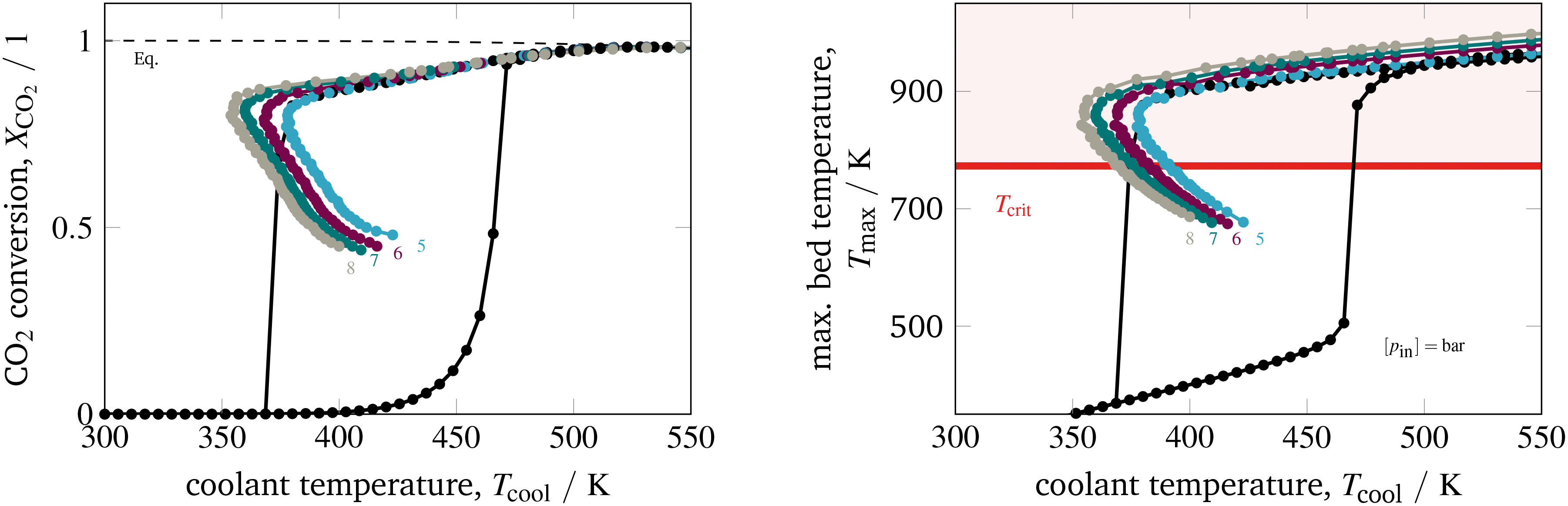 | ||
| Fig. 12 Stabilized operation regime for varying inlet pressures, reference model set-up: controlled (colored) and uncontrolled (black). | ||
The last parameter corresponds to the catalyst design. Currently, an increased interest on catalyst design under dynamic conditions can be observed in the literature. A comprehensive overview is provided by Kalz et al.9 Since our model also accounts for mass transport limitations within the catalyst (see section 3.2.3), we have been able to analyze in particular how diffusion limitations influence the dynamic stabilization of the temperature field. Therefore, we decide to vary the particle diameter dp, which directly influences the diffusion limitation via the effectiveness factor ηmeth (see eqn (16) and (17)). Fig. 13 illustrates this influence in case of larger catalyst particles (increased diffusion limitation) and smaller particles (decreased diffusion limitation).
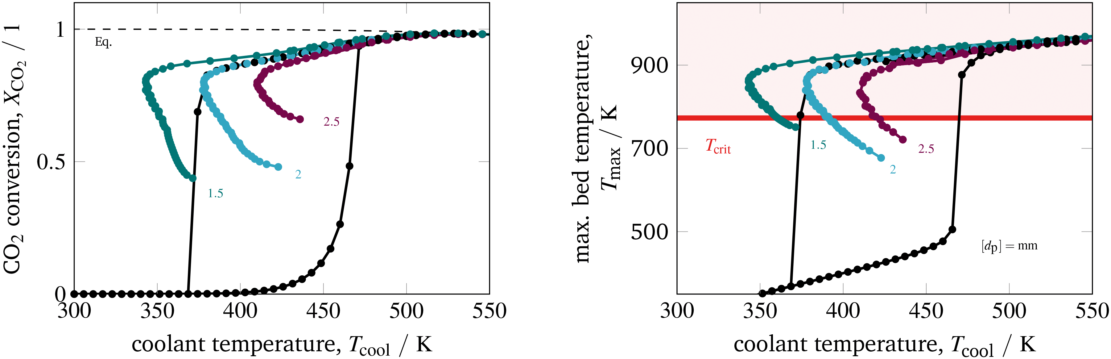 | ||
| Fig. 13 Stabilized operation regime for varying particle diameter, reference model set-up: controlled (colored) and uncontrolled (black). | ||
Compared to the other parameters from above, the particle diameter influence is even more pronounced. Larger particles and increased diffusion limitation lead to less reactive volume and less heat generation, which outweighs the influence on heat removal. Hence, the hysteresis loop shrinks, similar to the above illustrated reactor intensification. This weighting also remains for particle diameter reductions and lower diffusion limitations, so that heat generation dominates and leads to broader hysteresis loops. Consequently, diffusion limitation reveals an essential impact on the shape of the stabilization arc and, thus, also for any dynamic operation. Furthermore, we see that the particle diameter influence is significantly less pronounced when an operation apart from the stabilization arc and close to the chemical equilibrium is desired.
Due to its minor influence, we assume the pressure drop to be zero, so that the algebraic equations in eqn (20) vanish. Consequently, for any steady operation point (![[x with combining tilde]](https://www.rsc.org/images/entities/b_char_0078_0303.gif) ,ũ) the remaining nonlinear ODE system holds
,ũ) the remaining nonlinear ODE system holds
| 0 = f(,ũ). | (23) |
The linearization around this operation point leads to the following state-space formulation
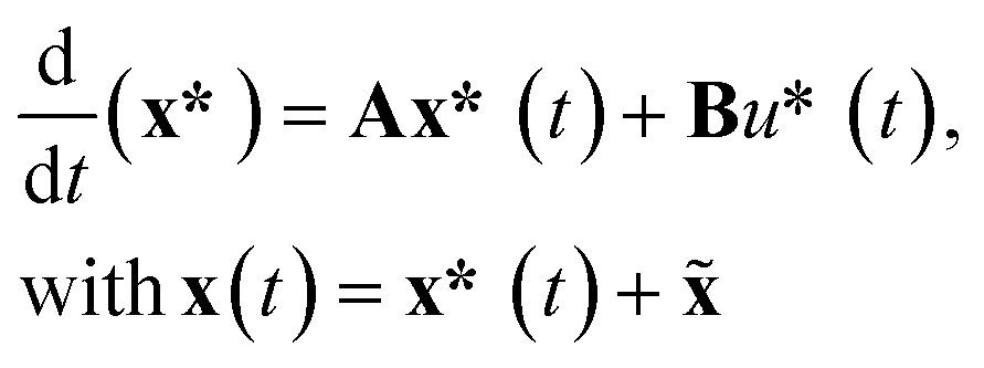 | (24) |
,ũ) with respect to x and u, respectively. Furthermore, A is used to obtain the eigenvalues λivia| (A − λiI)vi = 0, | (25) |
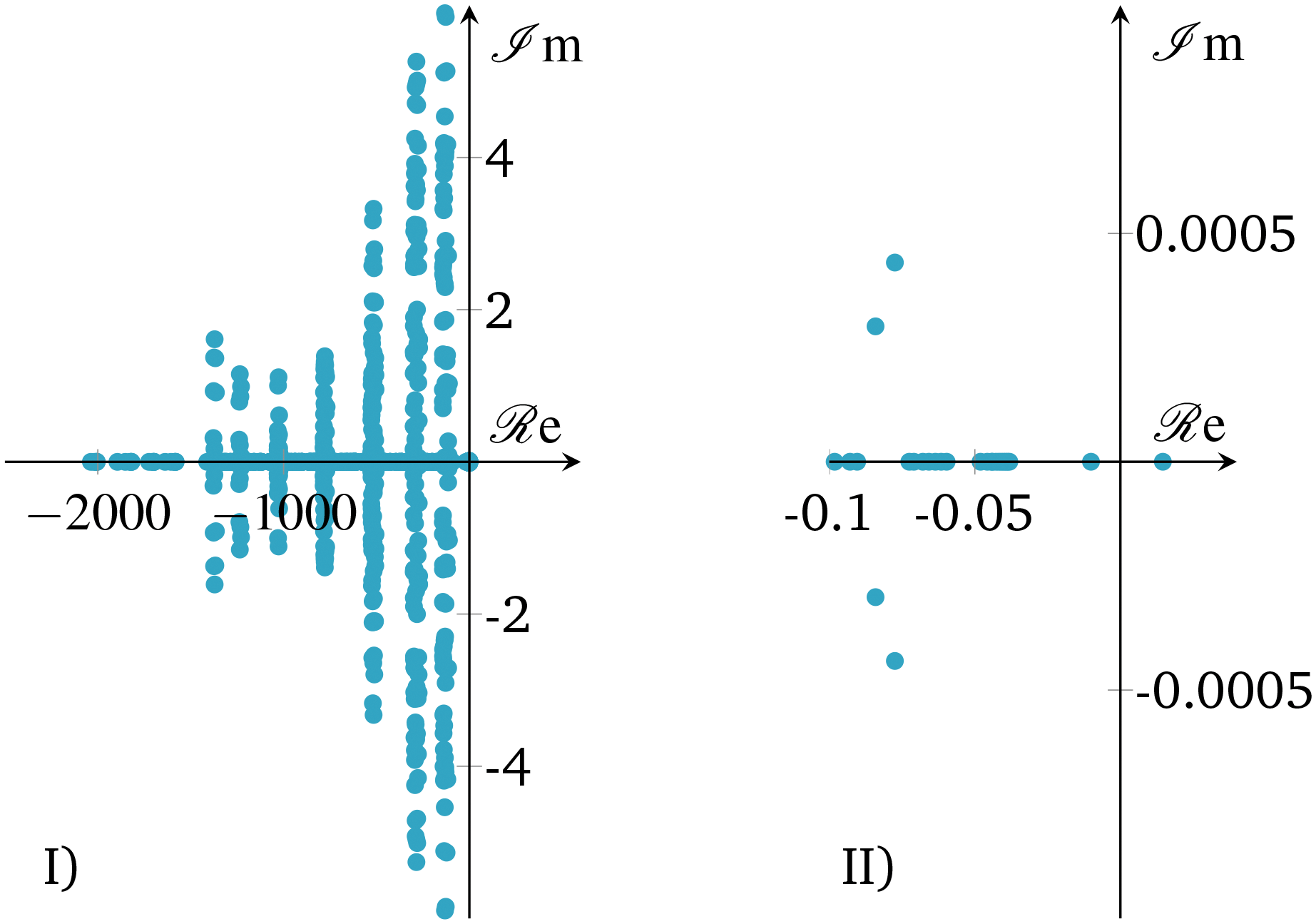 | ||
| Fig. 14 Open-loop eigenvalues of linearized state b) in Fig. 10; I) – full range, II) – largest eigenvalues. | ||
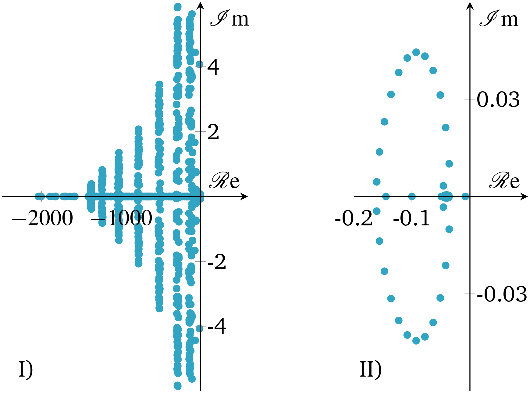 | ||
| Fig. 15 Closed-loop eigenvalues of linearized state b) in Fig. 10; I) – full range, II) – largest eigenvalues. | ||
The eigenvalue pattern confirms our observations from above. The open-loop system has a positive eigenvalue which leads to a divergent system behavior. However, there is only one positive eigenvalue very close to the origin pointing out that the instability is relatively weak/slow and potentially easy to stabilize. This was confirmed by applying a P-controller based on root locus analysis, showing that there is a broad range of different controller gains that shift positive eigenvalues/poles to the left-half plane. Nevertheless, a P-controller leads to significant set-point deviations, so that an additional integral part becomes inevitable. Consequently, our selected PI-controller from above shows a stabilization of the linearized system (see Fig. 15), as shown before for the nonlinear case.
Due to these results, the reactor stabilization can be locally proven with standard control theory. Furthermore, the observed unstable dynamics of the open-loop are rather slow and give rise to feasible controller implementations under real world scenarios with included measure and control delays, as well as uncertainties. Further discussions on technical aspects are part of the following section.
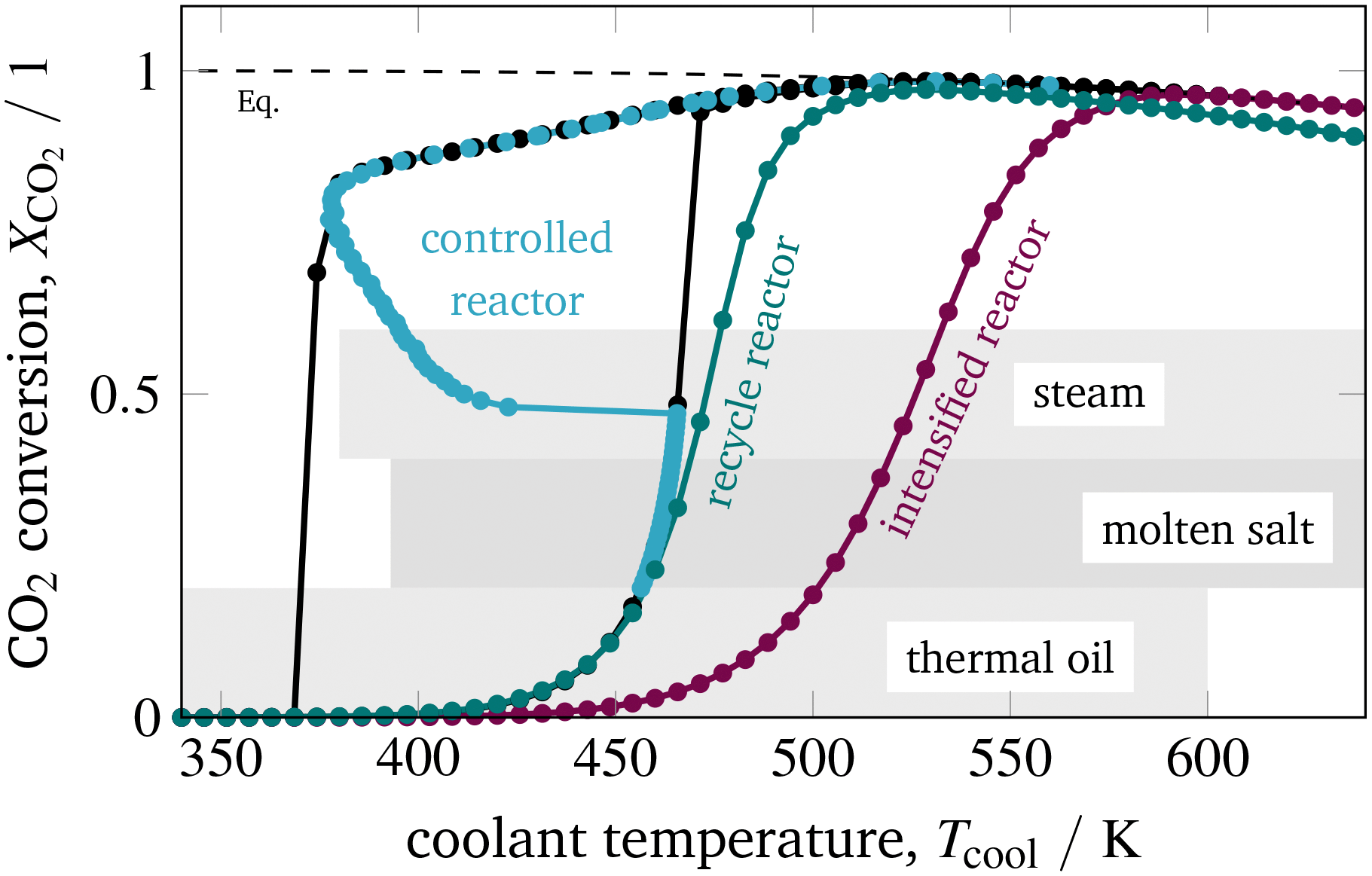 | ||
| Fig. 16 Coolant selection range related to prior case studies. | ||
Looking at the observed stabilized arc and its corresponding low cooling temperatures in Fig. 16 clarifies that only thermal oil appears to be an appropriate coolant for operating under these dynamic conditions. Molten salt and steam do not cover the low temperatures required for this special operation approach.
Despite explaining all technical details of each coolant option, we want to focus on their potentials for dynamic operation with regard to load changes and start-up time. Generally speaking, the more complex (e.g., due to many auxiliary units) a cooling system is, the more time it requires for start-up. Thermal oil cooling systems are known to be much simpler than steam and molten salt systems, which makes thermal oil a suitable candidate to ensure short start-up times. Choosing steam as coolant allows very fast coolant temperature changes to facilitate load changes by simply manipulating the coolant pressure. Nevertheless, this advantage comes with increased pressures and large mechanical stress. Changing the coolant temperature with a molten salt or a thermal oil cooling system requires potentially more time compared to a steam cooled system. However, general statements in this context need to be considered carefully since detailed response times of these systems in the context of control applications are scarcely available in the literature and often a matter of the specific design.
In particular, advanced control strategies as those proposed in this paper and in our previous study23 require not only sufficiently fast changes in the manipulated variable Tcool, but also in the controlled variable XCO2. In reality, both variables are certainly affected by response/reply delays, as well as uncertainties, depending on the involved actuators and sensors. Since measuring the conversion as done in this study is rather slow (e.g., when gas chromatography is used), one could also measure the bed temperature instead. Typically, these sensors and actuators are always required, also for steady process operation, which highlights the practicability of our proposed dynamic operation concept. However, further investigations with regard to response times and robustness need to be done in future works.
5 Conclusions
With this study on catalytic reactors we pay special attention to possible stabilization concepts for unstable operation regimes. To identify unstable regimes, an initial screening of stable steady-states is used for different catalytic reactor concepts. Such a screening reveals regimes with state-space multiplicity where unstable states can be expected in between. Our proposed reactor control concept turned out to be capable of approaching and stabilizing these states during operation. This way, we allow the reactor to be operated within a broader performance range and with increased flexibility.CO2 methanation offers a distinct potential for dynamic operation and flexibility enhancement. Due to its strong exothermicity, multiple stable and unstable states can easily arise from thermal feedbacks and hot-spot formations within an industrial scale fixed-bed reactor. Hence, the application of stabilized control is nothing more than controlling expanse and position of the reaction zone, so that a broader operation range becomes feasible. This broader operation range is very attractive when operational restrictions arise due to the catalyst durability. In case of CO2 methanation with very active catalytic materials, temperature limitations are very likely but not always possible to satisfy under conventional steady-state operation. In regions of multiple steady states, unstable arcs featuring high CO2 conversion and feasible catalyst temperatures exist and can be successfully approached by PI control. Without stabilizing control, similar achievements are possible when other reactor designs are considered (e.g., intensified reactors or product recycle/feed dilution). However, these designs still suffer from many technological obstacles, whereas the concept of stabilizing control can be applied to state-of-the-art reactor configurations that are widely used for large scale production units.
In future investigations these model-based results still need to be underpinned by experimental validation in order to provide the final prove of concept. Nevertheless, the good model agreement with other studies, as well as the detailed systematic analyses, indicate that our results are at least qualitatively reliable and represent the right direction to uncover potentials coming from dynamic reactor operation. In this regard, catalytic properties have shown a tremendous impact on the dynamic behavior, suggesting that future investigations need to be aligned in this direction. Thereby, more detailed dynamic models for the catalyst particle are required to be incorporated into the current reactor model. Features like diffusion limitation or heat capacity are certainly the right choice for optimized dynamic reactor designs and might offer possibilities that allow an easier and more robust stabilization and lead to lower technical requirements on the entire control loop.
List of symbols
Latin
| Bo | Bodenstein number (—) |
| c | Concentration (mol m−3) |
| c p | Heat capacity (J kg−1 K−1) |
| Diffusion coefficient (m2 s−1) |
| d | Diameter (m) |
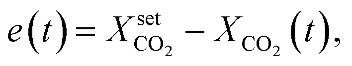
| e | Set-point deviation (—) |
| j | Mass flux (kg m−2 s−1) |
| k | Heat transport coefficient (W m−1 K−1) |
| k | Reaction rate constant (various) |
| K | Adsorption and equilibrium constant (various) |
| K | Controller parameter (various) |
| L | Reactor length (m) |
| M | Molar mass (kg mol−1) |
| Pe | Péclet number (—) |
| Pr | Prandtl number (—) |
| p | Pressure (bar) |
![[q with combining dot above]](https://www.rsc.org/images/entities/i_char_0071_0307.gif)
| Heat flux (W m−2) |
![[Q with combining dot above]](https://www.rsc.org/images/entities/i_char_0051_0307.gif)
| Heat flow (W) |
| r | Mass-based reaction rate (various) |
![[r with combining tilde]](https://www.rsc.org/images/entities/char_0072_0303.gif) | Molar reaction rate (mol mcat−3 s−1) |
| r | Radial coordinate (m) |
| R | Tube inner radius (m) |
![[scr R, script letter R]](https://www.rsc.org/images/entities/char_e531.gif) | Universal gas constant (J mol−1 K−1) |
| Re | Reynolds number (—) |
| T | Temperature (K) |
| t | Time (s) |
| u | Control (K) |
| v z | Superficial velocity (m s−1) |
| w | Mass fraction (—) |
| X | Conversion (—) |
| x | Molar fraction (—) |
| z | Axial coordinate (m) |
| x | differential state (—) |
| z | algebraic state (—) |
Greek
| α | Heat transport coefficient (W m−2 K−1) |
| ΔR0 | Reaction enthalpy (STP) (J mol−1) |
| δ | Wall thickness (m) |
| η | Catalyst effectiveness factor (—) |
| γ | Inactive, adiabatic model zone (m) |
| λ | Thermal conductivity (W m−1 K−1) |
| μ | Dynamic viscosity (Pa s) |
| ν | Stoichiometric coefficient (—) |
| ϕ | Thiele modulus (—) |
| φ | Azimuthal coordinate (°) |
| ρ | Density (kg m−3) |
| τ | Tortuosity (—) |
| ε | Void fraction (—) |
Subscripts
| α | Component {CH4, CO, CO2, H2 O, H2, N2} |
| β | Reaction |
| bed | Catalyst bed |
| cat | Catalyst phase |
| cond | Conduction |
| cool | Cooling |
| crit | Critical |
| eq | Equilibrium |
| ext | Extinction |
| gas | Gas phase |
| h | Hydraulic |
| I | Integral term |
| ign | Ignition |
| in | Inlet |
| jac | Jacket |
| Kn | Knudsen |
| m | Molecular |
| max | Maximal |
| meth | Methanation |
| mix | Mixture |
| P | Proportional term |
| p | Particle |
| pore | Pore |
| r | Radial |
| rad | Radiation |
| w | Wall |
| z | Axial |
List of abbreviations
| IA | Ignition Arc |
| EA | Extinction Arc |
| ESI | Electronic supplementary information |
| PDE | Partial differential equation |
| DAE | Differential algebraic system |
| LHHW | Langmuir–Hinshelwood Hougen–Watson |
| CSTR | Continuously stirred tank reactor |
| PFTR | Plug flow tubular reactor |
| SMR | Steam methane reforming |
| FV | Finite volume |
| DEN | Denominator |
| STP | Standard temperature and pressure |
Conflicts of interest
There are no conflicts to declare.Acknowledgements
This research is supported by the International Max Planck Research School (IMPRS) for Advanced Methods in Process and Systems Engineering, Magdeburg, Germany. In addition, we would like to thank Lars Kiewidt for the fruitful discussions and model comparisons regarding catalyst and heat transport properties which helped us to further strengthen the modeling results presented in this study. Kai Sundmacher gratefully acknowledges support of his research on CO2 methanation reactors and catalysts by the German Research Foundation (DFG) under the grant SU 189/8-1. Open Access funding provided by the Max Planck Society.References
- Handbook of Heterogeneous Catalysis, ed. G. Ertl, H. Knözinger, F. Schüth and J. Weitkamp, Wiley-VCH Verlag GmbH & Co. KGaA, Weinheim, Germany, 2008 Search PubMed.
- G. Eigenberger and W. Ruppel, Ullmann's Encyclopedia of Industrial Chemistry, Wiley-VCH Verlag GmbH & Co. KGaA, 2000 Search PubMed.
- G. Eigenberger, Handbook of Heterogeneous Catalysis, Wiley-VCH Verlag GmbH & Co. KGaA, Weinheim, Germany, 2008 Search PubMed.
- U. Hoffmann and K. Sundmacher, Chem. Ing. Tech., 1997, 69, 613–622 CrossRef CAS.
- D. W. Agar and W. Ruppel, Chem. Ing. Tech., 1988, 60, 731–741 CrossRef CAS.
- G. Kolios, J. Frauhammer and G. Eigenberger, Chem. Eng. Sci., 2000, 55, 5945–5967 CrossRef CAS.
- G. A. Bunimovich, P. L. Silverston and J. Š. Matros, Handbook of Heterogeneous Catalysis, Wiley-VCH Verlag GmbH & Co. KGaA, Weinheim, Germany, 2008 Search PubMed.
- J. Š. Matros, Catalytic processes under unsteady-state conditions, Elsevier, Amsterdam, 1989, vol. 43 Search PubMed.
- K. F. Kalz, R. Kraehnert, M. Dvoyashkin, R. Dittmeyer, R. Gläser, U. Krewer, K. Reuter and J.-D. Grunwaldt, ChemCatChem, 2017, 9, 17–29 CrossRef CAS PubMed.
- F. J. M. Horn and R. C. Lin, Ind. Eng. Chem. Process Des. Dev., 1967, 6, 21–30 CrossRef CAS.
- E. D. Gilles, Chem. Ing. Tech., 1968, 40, 469–477 CrossRef CAS.
- R. Aris, Elementary Chemical Reactor Analysis, Prentice-Hall, Englewood Cliffs, 1969 Search PubMed.
- A. Stankiewicz and M. Kuczynski, Chem. Eng. Process.: Process Intesif., 1995, 34, 367–377 CrossRef CAS.
- S. Rönsch, J. Schneider, S. Matthischke, M. Schlüter, M. Götz, J. Lefebvre, P. Prabhakaran and S. Bajohr, Fuel, 2016, 166, 276–296 CrossRef.
- D. Schlereth, Kinetic and Reactor Modeling for the Methanation of Carbon Dioxide, PhD thesis, Technical University of Munich, 2015 Search PubMed.
- M. Sudiro, A. Bertucco, G. Groppi and E. Tronconi, 20th European Symposium on Computer Aided Process Engineering, Elsevier, 2010, vol. 28, pp. 691–696 Search PubMed.
- E. Tronconi, G. Groppi, T. Boger and A. Heibel, Chem. Eng. Sci., 2004, 59, 4941–4949 CrossRef CAS.
- K. P. Brooks, J. Hu, H. Zhu and R. J. Kee, Chem. Eng. Sci., 2007, 62, 1161–1170 CrossRef CAS.
- M. Belimov, D. Metzger and P. Pfeifer, AIChE J., 2017, 63, 120–129 CrossRef CAS.
- E. Bianchi, T. Heidig, C. G. Visconti, G. Groppi, H. Freund and E. Tronconi, Catal. Today, 2013, 216, 121–134 CrossRef CAS.
- L. Kiewidt, Solid sponges as support for heterogeneous catalysts in gas-phase reactions, PhD thesis, Univ. Bremen, 2017 Search PubMed.
- S. Matthischke, R. Krüger, S. Rönsch and R. Güttel, Fuel Process. Technol., 2016, 153, 87–93 CrossRef CAS.
- J. Bremer, K. H. G. Rätze and K. Sundmacher, AIChE J., 2017, 63, 23–31 CrossRef CAS.
- L. Kiewidt and J. Thöming, Chem. Eng. Sci., 2015, 132(2015), 59–71 CrossRef CAS.
- A. El Sibai, L. K. Rihko Struckmann and K. Sundmacher, Energy Technol., 2017, 5, 911–921 CrossRef CAS.
- D. Schlereth and O. Hinrichsen, Chem. Eng. Res. Des., 2014, 92, 702–712 CrossRef CAS.
- J. H. Ghouse and T. A. Adams, Int. J. Hydrogen Energy, 2013, 38, 9984–9999 CrossRef CAS.
- L. Lao, A. Aguirre, A. Tran, Z. Wu, H. Durand and P. D. Christofides, Chem. Eng. Sci., 2016, 148, 78–92 CrossRef CAS.
- S. Matthischke, S. Roensch and R. Güttel, Ind. Eng. Chem. Res., 2018, 57(18), 6391–6400 CrossRef CAS.
- D. Sun and D. S. Simakov, J. CO2 Util., 2017, 21, 368–382 CrossRef CAS.
- G. Eigenberger and H. Schuler, Int. Chem. Eng., 1989, 29(1), 12–25 Search PubMed.
- G. Eigenberger, Chem. Ing. Tech., 1983, 55, 503–515 CrossRef CAS.
- M. Morbidelli, A. Varma and R. Aris, Chemical reaction and reactor engineering, Dekker, New York, NY, 1987, vol. 26 Search PubMed.
- D. Luss, Dynamics and Modelling of Reactive Systems, Elsevier Science, Burlington, 2014, pp. 131–159 Search PubMed.
- M. Feinberg, Chem. Eng. Sci., 1988, 43, 1–25 CrossRef CAS.
- E. D. Gilles, Chem. Ing. Tech., 1977, 49, 142–149 CrossRef CAS.
- F. Koschany, D. Schlereth and O. Hinrichsen, Appl. Catal., B, 2016, 181, 504–516 CrossRef CAS.
- M. Morbidelli and A. Varma, AIChE J., 1982, 28, 705–713 CrossRef CAS.
- R. F. Heinemann and A. B. Poore, Chem. Eng. Sci., 1981, 36, 1411–1419 CrossRef CAS.
- K. F. Jensen and W. Ray, Chem. Eng. Sci., 1982, 37, 199–222 CrossRef CAS.
- V. Balakotaiah and D. H. West, Curr. Opin. Chem. Eng., 2014, 5, 68–77 CrossRef.
- V. B. Pai, J. L. Gainer and G. Carta, Fundamentals of Adsorption, Springer US, Boston, MA, 1996, vol. 356, pp. 733–740 Search PubMed.
- J. Š. Matros and G. A. Bunimovich, Catal. Rev.: Sci. Eng., 1996, 38, 1–68 CrossRef.
- P. L. Silveston, Composition modulation of catalytic reactors, Gordon & Breach, Amsterdam, 1998, vol. 11 Search PubMed.
- A. Marković, A.-S. Morgenstern and M. Petkovska, Chem. Eng. Res. Des., 2008, 86, 682–691 CrossRef.
- R. R. Hudgins, P. L. Silveston, A. Renken and Y. S. Matros, Periodic operation of reactors, Elsevier and Butterworth-Heinemann, Amsterdam and Waltham, Mass., 2013, pp. 1–22 Search PubMed.
- R. Güttel, Chem. Eng. Technol., 2013, 36, 1675–1682 Search PubMed.
- B. Kreitz, G. D. Wehinger and T. Turek, Chem. Eng. Sci., 2019, 195, 541–552 CrossRef CAS.
- R. Aris and N. R. Amundson, Chem. Eng. Sci., 1958, 7, 121–131 CrossRef CAS.
- F. Viel, F. Jadot and G. Bastin, Automatica, 1997, 33, 1437–1448 CrossRef.
- D. Dochain, M. Perrier and B. E. Ydstie, Chem. Eng. Sci., 1992, 47, 4167–4177 CrossRef CAS.
- J. Alvarez-Ramirez and J. Alvarez, International Journal of Robust and Nonlinear Control, 2006, 16, 113–131 CrossRef.
- M. Bakošová, D. Puna, P. Dostál and J. Závacká, Chem. Pap., 2009, 63, 3042 Search PubMed.
- J. A. Moreno, J. Alvarez, E. Rocha-Cózatl and J. Diaz-Salgado, IFAC Proceedings Volumes, 2010, 43, 727–732 CrossRef.
- M. Bakošová, A. Mészáros, J. J. Klemeš and J. Oravec, Theor. Found. Chem. Eng., 2012, 46, 740–746 CrossRef.
- M. Gassner and F. Maréchal, Energy Environ. Sci., 2012, 5, 5768 RSC.
- A. Sternberg and A. Bardow, Energy Environ. Sci., 2015, 8, 389–400 RSC.
- R. Try, A. Bengaouer, P. Baurens and C. Jallut, AIChE J., 2018, 64(2), 468–480 CrossRef CAS.
- D. Bongartz, L. Doré, K. Eichler, T. Grube, B. Heuser, L. E. Hombach, M. Robinius, S. Pischinger, D. Stolten, G. Walther and A. Mitsos, Appl. Energy, 2018, 231, 757–767 CrossRef CAS.
- G. Liesche and K. Sundmacher, Chem. Eng. J., 2018 DOI:10.1016/j.cej.2018.09.209 , in press.
- J. Uebbing, L. K. Rihko-Struckmann and K. Sundmacher, Appl. Energy, 2019, 233–234, 271–282 CrossRef CAS.
- J. Gao, Y. Wang, Y. Ping, D. Hu, G. Xu, F. Gu and F. Su, RSC Adv., 2012, 2, 2358 RSC.
- J. Xu and G. F. Froment, AIChE J., 1989, 35, 88–96 CrossRef CAS.
- J. Pérez-Ramírez, Catal. Today, 2000, 60, 93–109 CrossRef.
- E. L. Oliveira, C. A. Grande and A. E. Rodrigues, Chem. Eng. Sci., 2010, 65, 1539–1550 CrossRef CAS.
- T. Fischedick, M. Kind and B. Dietrich, Int. J. Therm. Sci., 2015, 96, 1–11 CrossRef CAS.
- O. Levenspiel and W. K. Smith, Chem. Eng. Sci., 1995, 50, 3891–3896 CrossRef CAS.
- M. F. Edwards and J. F. Richardson, Chem. Eng. Sci., 1968, 23, 109–123 CrossRef CAS.
- J. M. P. Q. Delgado, Heat Mass Transfer, 2006, 42, 279–310 CrossRef CAS.
- H. Freund, Ortsaufgelöste Simulation von Transportprozessen in durchströmten Festbetten: Zugl.: Erlangen-Nürnberg, Univ., Diss., 2007, Shaker, Aachen, 2008 Search PubMed.
- A. G. Dixon and D. L. Cresswell, AIChE J., 1979, 25, 663–676 CrossRef CAS.
- E. Tsotsas, VDI Heat Atlas, Springer, Berlin Heidelberg, 2010, pp. 1327–1342 Search PubMed.
- R. Bauer and E. U. Schluender, Int. Chem. Eng., 1978, 18, 189–204 Search PubMed.
- J. Ducamp, A. Bengaouer and P. Baurens, Can. J. Chem. Eng., 2017, 95, 241–252 CrossRef CAS.
- C. R. Wilke and P. Chang, AIChE J., 1955, 1, 264–270 CrossRef CAS.
- K. B. Bischoff, AIChE J., 1965, 11, 351–355 CrossRef CAS.
- J. A. E. Andersson, J. Gillis, G. Horn, J. B. Rawlings and M. Diehl, Math. Program. Comput., 2019, 11(1), 1–36 CrossRef.
- A. C. Hindmarsh, P. N. Brown, K. E. Grant, S. L. Lee, R. Serban, D. E. Shumaker and C. S. Woodward, ACM Trans. Math. Softw., 2005, 31, 363–396 CrossRef.
- S. Abate, C. Mebrahtu, E. Giglio, F. Deorsola, S. Bensaid, S. Perathoner, R. Pirone and G. Centi, Ind. Eng. Chem. Res., 2016, 55, 4451–4460 CrossRef CAS.
- M. Martinez Molina, C. Kern and A. Jess, Chem. Eng. Technol., 2016, 39, 2404–2415 CrossRef.
- G. Eigenberger, Ullmann's Encyclopedia of Industrial Chemistry, Wiley-VCH Verlag GmbH & Co. KGaA, 2000 Search PubMed.
- O. Kalthoff and D. Vortmeyer, Chem. Eng. Sci., 1980, 35, 1637–1643 CrossRef CAS.
- Chemical reaction and reactor engineering, ed. J. J. Carberry, Dekker, New York, NY, 1987, vol. 26 Search PubMed.
- S. Wedel and D. Luss, Ind. Eng. Chem. Fundam., 1984, 23, 280–288 CrossRef CAS.
- J. B. Rawlings and J. G. Ekerdt, Chemical reactor analysis and design fundamentals, Nob Hill Publishing, Madison, Wisconsin, 2nd edn, 2013 Search PubMed.
Footnote |
| † Electronic supplementary information (ESI) available: One PDF documents and five movies/animations. See DOI: 10.1039/c9re00147f |
| This journal is © The Royal Society of Chemistry 2019 |