 Open Access Article
Creative Commons Attribution 3.0 Unported Licence
A versatile liquid-jet/sessile droplet system for operando studies of reactions in liquid dispersions and solutions by X-ray absorption spectroscopy†
S.-Y.
Chang
 ac,
T. A.
Kathyola
 a,
E. A.
Willneff
 b,
Colin John
Willis
d,
P.
Wilson
d,
P. J.
Dowding
 ad,
G.
Cibin
 c,
A. B.
Kroner
 c,
E. J.
Shotton
 c and
S. L. M.
Schroeder
 *ac
*ac
aSchool of Chemical and Process Engineering, University of Leeds, Leeds, LS2 9JT, UK. E-mail: s.l.m.schroeder@leeds.ac.uk
bSchool of Design, University of Leeds, Leeds, LS2 9JT, UK
cDiamond Light Source, Didcot, Oxfordshire OX11 0DE, UK
dInfineum UK Ltd, Abingdon, Oxfordshire OX13 6BB, UK. E-mail: colin.willis@infineum.com
First published on 25th February 2019
Abstract
Herein, we designed a versatile cell for operando X-ray absorption spectroscopy (XAS) monitoring of chemical and physical transformations in liquid solutions and dispersions by fluorescence-yield detection. The cell operates under atmospheric pressure, and the composition of the gas phase can be varied, allowing monitoring of gas–liquid reactions. Samples can be examined as a flowing liquid-jet or as a sessile droplet. Both liquid-jet and droplet operations of the cell were demonstrated at the Ca K-edge through time-resolved studies of CaCO3 formation from CO2 and solid Ca(OH)2 in an aqueous suspension. The liquid-jet reaction was performed at 28 °C, and the droplet reaction was performed at ambient temperature, but both configurations had the scope to be modified for operations at higher temperatures. The liquid-jet volumes were recycled, permitting the use of the cell in a continuous sampling loop for process studies in larger reactor vessels. The jet supply tube was interchangeable, permitting adjustment of the jet size through the tubing bore size. Larger bore sizes minimized the pressure drop at the nozzle and thereby the risk of blockage of the liquid supply by the suspended particulates or growth of solid deposits. Sessile droplet operation enabled studies with minimal sample volumes and mechanical disturbances under controlled environmental conditions. The cell is portable and modular and is based on readily available standard vacuum equipment parts. Furthermore, the operation under a He atmosphere allows measurements above 4 keV, covering part of the tender X-ray range, and it is also applicable to the hard X-ray range.
1. Introduction
X-ray absorption spectroscopy (XAS) provides element-specific molecular-level information about the local electronic structure of materials and thus deep insight into their chemical speciation including oxidation states and local coordination geometry. Its sensitivity to short-range structures renders it particularly attractive for the characterization of systems, such as amorphous materials and liquids, including solutions, suspensions, emulsions and melts, without a long-range order.1 Studies on the electronic structure and local bonding in these systems are of multi-disciplinary relevance, including chemistry (e.g. catalysis, synthesis, self-assembly, and electrochemistry), biology (membrane function and metalloproteins), physics (super- and semiconductors, magnetism, and glasses), environmental science (soil remediation and waste), materials science (functional materials, biomaterials, and ceramics) and engineering (separations, corrosion, electronics, and photonics).1For X-ray absorption edges in the hard X-ray range (photon energies above 5 keV), XAS is a versatile technique for probing reactions and physical transformations in situ and operando because hard X-rays readily penetrate air and many X-ray window materials. Thus, the probing of many high temperature and pressure sample environments using hard X-rays have been reported, e.g. for hydrothermal and catalytic applications.2,3
For X-ray photon energies below 5 keV, air and window materials significantly attenuate the photon flux. The photon energy range between 1 and 5 keV (often referred to as the ‘tender’ X-ray range) is of current interest because it includes the K absorption edges of important elements in the 3rd and 4th period (from Na to Ca) as well as the L-edges of elements ranging from Zn to Cs. To minimize X-ray absorption by ambient gases, the sample environment is either flushed with a weakly absorbing gas (typically He) or evacuated using vacuum pumps. X-ray transparent windows are required for incident X-rays to reach the sample and also for transmitted/fluorescent X-rays to reach the detector. Window materials that are suitably transparent for applications in the tender X-rays range include polyimide, Mylar, polymers and ultrathin beryllium; however, they have limited scope for experiments at elevated temperatures and pressures and in the presence of chemical reactants that may corrode, dissolve or decompose the window materials.4 These requirements restrict the scope for in situ and/or operando reactor design, often rendering reaction conditions, for example operating temperature, pressure and multi-component heterogeneous processes in liquid phase, a poor model of the actual process of interest. Nevertheless, operando electrochemical cells have been developed for measurements at the S K- and P K-edges.5,6
For multiphase liquid–solid dispersion samples, it is preferable to have windowless probing. When a process involves nucleation, adsorption or precipitation of solid particles, deposition on the window materials can occur, resulting in XAS analysis of an unrepresentative aliquot of the reaction mixture.7 For tender X-ray experiments, fluorescence-yield (FY) detection is particularly affected compared with transmission as it is surface rather than bulk sensitive. Windowless probing of multiphase samples avoids these problems and has been explored for a variety of X-ray sample environments, including supported and hanging droplets,8,9 levitated droplets,10 static solutions11,12 and liquid-jets.13
We developed an inexpensive and versatile ambient pressure cell with the capability of probing a wide range of dynamic gas–liquid–solid systems through windowless liquid-jet operation. Operating under an He flow at atmospheric pressure facilitates measurements in the tender X-ray range above 3–4 keV. The cell was constructed from standard vacuum parts and fittings for gas or liquid streams. After X-ray probing, the liquid volume is collected and fed back to the supply vessel, facilitating an external sampling loop for the continuous monitoring of reactions without loss in sample volume. This provides the capability for operando process studies using large reaction vessels with control over the gas environment and temperature. To allow studies of viscous and/or multiphase systems in the presence of solid particulates, the inner diameter and length of the jet inlet tube can be varied and optimized. High flow rates also enable short residence time in the flow loop, with associated minimization of heat losses and radiation damage by absorbed X-rays.
Herein, we demonstrate the construction and operation of the cell. We present data for the reactive crystallization of CaCO3 from an aqueous calcium hydroxide (Ca(OH)2) dispersion at 28 °C using the liquid-jet configuration with a controlled gas phase environment. Specifically, in this study, the system is a ‘dispersion-jet’ rather than a ‘liquid-jet’, but we use the term ‘liquid-jet’ to emphasize the fact that our system uses a pressurized jet system in the same way as conventional liquid-jet sampling environments.14 We complement this work by following the formation of CaCO3 at the gas–liquid interface between a sessile droplet of a saturated Ca(OH)2 solution with CO2 dosed directly into the analysis chamber.
Finally, it should be mentioned that in the soft X-ray range (at photon energies below 1 keV), the absorption of photons by air is so strong that experiments are traditionally performed in vacuum chambers. For studies of liquids, transmission flow cells were constructed, in which a few hundred nm-thick liquid sample is separated from the vacuum environment using two windows.15,16 The currently most common form of liquid sample delivery into vacuum chambers is via liquid-microjets, with fluorescence- or electron-yield detection of the absorption spectra.14 Moreover, in situ and operando liquid cells for soft X-rays have recently been developed for electrochemical, heterogeneous catalysis and more recently, for high pressure applications.4,17–19 The setup reported herein was inspired by these microjet cells.
2. Experimental
2.1 Material
Geological CaCO3 powder (calcite, ≥99%, Sigma Aldrich, UK) and Ca(OH)2 (94%, L'Hoist, UK) were used. Deionized water was utilized throughout the experiments. He, N2 and CO2 (BIP purity) from Air Products were used.2.2 XAS experiments
XAS measurements were carried out at Diamond Light Source, UK on beamline B18 at the Ca K-edge (ca. 4 keV).20 An Si (111) double crystal monochromator was used. The synchrotron was operated at 3 GeV with a ring current of 300 mA. For the recycling liquid-jet experiments, the beam footprint was 800 μm in height and 600 μm in width. For the sessile droplet experiments, the beam footprint was 1.2 mm in height and 1.8 mm in width. The dwell time was 0.14 second eV−1 for the droplet measurements and 0.2 second eV−1 for the liquid-jet measurements. Measurement of each spectrum took one to three minutes. The liquid phase spectra were collected in the FY mode using a 4-element SII Vortex silicon-drift detector with XSPRESS3 electronics. The solid phase reference samples Ca(OH)2 and calcite were spread on double-sided carbon tapes and measured using gas flow total electron yield (TEY) detection. A metal electron collector was positioned 1 cm from the sample and biased at +63 V using a battery box.All experimental data were processed using Athena in the Demeter software package.21 The changes in sample compositions due to carbonation were quantified using linear combination fitting (LCF) of X-ray absorption near edge structure (XANES) spectra over the energy range of 4000 to 4130 eV. The components used for the LCF were the spectra of solid phase calcite and Ca(OH)2 as well as the spectrum of a saturated 18.8 mM Ca(OH)2 or Ca2+ solution, where mM indicates mmol L−1.
2.3 The environmental cell/the analysis chamber
The environmental cell was constructed from commercially available standard parts including ConFlat (CF) vacuum parts, polyimide films and standard glassware to ensure ease of assembly and reproducibility. The construction of the environmental cell was based on a CF40 flange ultrahigh vacuum cube. The schematics of the setup shown in Fig. 1 and 2 show that the incident X-rays entered via a windowless port. At the opposite end of the cell, a 75 μm thick polyimide window was positioned for X-ray transmission measurements, which is required for alignment of the sample in the X-ray beam. A second polyimide window was fixed to a port located perpendicular to the direction of the X-ray beam, which allowed for the positioning of an external fluorescence-yield detector with minimal air path (Fig. 2). Accordingly, the fluorescence detector was positioned at approximately 40 mm away from the sample in the center of the cell. The other 90° port held a fast-entry load lock, which also served as a viewport for visible monitoring with a camera. A 5 × CF16 cluster flange mounted on top permitted the addition of various feedthroughs including the helium gas inlet, which was fed through a 1/8′′ Swagelok fitting and a glass tubing, which was fed through a 1/4′′ quick-connect adaptor single fitting (Kurt J. Lesker). The analysis chamber was maintained in a helium environment to minimize absorption in the tender X-ray range. All other unused ports were closed off with blank flanges to maintain a closed system.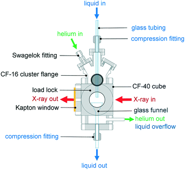 | ||
| Fig. 1 The environmental cell dedicated to liquid-jet and droplet operation under a controlled gas environment. | ||
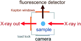 | ||
| Fig. 2 Aerial view of the CF40 cube showing the positions of the fluorescence detector, camera and X-ray beam path. | ||
The cell was attached to the beamline via a flexible KF40 bellow positioned after the ion chamber that monitored the intensity of the incident X-ray beam. The bellow gave flexibility to align the position of the environmental cell relative to the X-ray beam. The environmental cell was mechanically supported to the beamline via metal posts attached to a motorized stage. The cell is also portable, enabling users to move it between home institutions and synchrotron light sources and/or between beamlines.
The cell was operated in two configurations, either as a recycling liquid-jet cell or as a droplet cell, as follows.
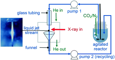 | ||
| Fig. 3 Recycling liquid-jet configuration for monitoring the operando carbonation of a Ca(OH)2 aqueous dispersion at the Ca K-edge. | ||
To collect the sample volume for recycling, a custom-made glass funnel (top cone diameter 25 mm and stem diameter 6 mm) was fixed at the bottom of the cube. The glass stem was fed through a CF to quick-connect coupling single adaptor to fit the CF40 cube. All materials used for the construction of the flow loop were compatible with organic solvents, including the Viton tubing for use with the peristaltic pump, Viton gaskets, glass reactor, glass tubing and stainless steel cell body.
To demonstrate the capability of the liquid-jet cell, we followed the operando carbonation of a supersaturated aqueous dispersion of Ca(OH)2 (75 mM). 750 mL of the dispersion was mixed in a 1 L glass reactor using an overhead stirrer at 400 rpm. The CF40 cube chamber was constantly flushed with 1 L min−1 helium to maximize X-ray transmission. Overall, the small volume of the CF40 cube required less than ten minutes to be purged by helium gas. Prior to the XAS measurements and the carbonation reaction, the reaction mixture was purged with 30 mL min−1 of N2 gas to minimize the influx of atmospheric CO2. For the carbonation reactions, the Ca(OH)2 dispersion was purged with 57 mL min−1 CO2 and 30 mL min−1 N2. After 20 min of carbonation, the CO2 flow was stopped. To ensure complete monitoring of the reaction between Ca(OH)2 and the reactant (CO2), XAS measurements were continued up to 15 min after the CO2 flow was terminated. During reaction, the content of the glass vessel was maintained at 28 ± 2 °C using a temperature feedback loop consisting of a thermocouple, heating mantle, cooling coil and West N4400 temperature controller. The temperature regulation system was also a safety feature to prevent overheating during the exothermic carbonation reaction. Before carrying out the experiments, the sampling loop was flushed thoroughly with dilute acid and deionized water.
3. Results
The liquid-jet and droplet environmental cells were tested by monitoring the Ca K-edge, following the formation of CaCO3 from Ca(OH)2 in the presence of CO2 gas. These experiments demonstrated the ability of the cell: (i) to handle tender X-rays (∼4 keV) through use of an He environment, (ii) to accommodate multiphase systems, as exemplified by the three-phase gas–liquid–solid system; and (iii) to generate X-ray absorption spectra of sufficient quality to monitor the progress of the carbonation reaction.3.1 Recycling liquid-jet
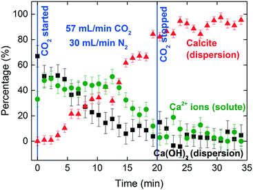
The XANES spectra in Fig. 5 show the gradual transformation of Ca(OH)2 to calcite over a period of 30 min. This demonstrates the successful handling of a multiphase system containing gas, liquid and dispersion for XAS analysis at the Ca K-edge. Before carbonation, LCF analysis of the XANES spectrum showed that within the volume of the stream probed, there was a mixture of 33% dissolved Ca2+ species and 67% Ca(OH)2 dispersion (Fig. 6). After CO2 was introduced into the system, the composition of Ca(OH)2 decreased steadily with time. For the first 12 minutes of carbonation, the content of Ca2+ ions fluctuated at around 40% while the supply of Ca(OH)2 gradually decreased (Fig. 7). After 12 minutes, the content of Ca2+ ions started to decrease. The decrease in Ca(OH)2 and Ca2+ ions was accompanied by the formation of calcite, as evident from the gradual increase in the intensity of the shoulder at 4045 eV of the pre-edge region and the modulation at the 4060 eV region (Fig. 5). At the end of the carbonation reaction, calcite dominated the composition of the system. Overall, the LCF analysis of the liquid-jet system suggests a three-step reaction mechanism: (i) the dissolution of solid Ca(OH)2 to give aqueous Ca2+ ions; (ii) the dissolution of CO2 gas to give aqueous CO32− ions; and (iii) the reaction of the aqueous Ca2+ and CO32− ions to form solid calcite.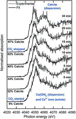 | ||
| Fig. 5 Time-dependent Ca K-edge XANES spectra of the operando carbonation of 75 mM Ca(OH)2 using the recycling liquid-jet configuration. | ||
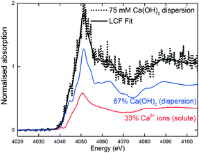 | ||
| Fig. 6 LCF of the 75 mM aqueous Ca(OH)2 dispersion in the liquid-jet configuration before CO2 was introduced. | ||
3.2 Sessile droplet
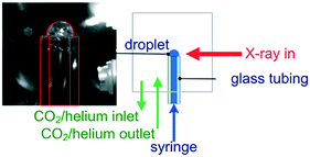
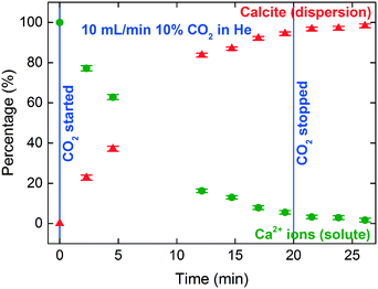
The sessile droplet allowed observation of the direct formation of calcite from dissolved Ca2+ ions but at the gas–liquid interface (Fig. 8 and 9). With the aid of a high-resolution camera (Fig. 4), we observed the formation of an inhomogeneous opaque film across the surface of the droplet as carbonation progressed. The visible film is likely to be a thin layer of calcite formed at the gas–liquid interface by carbonation, as evidenced from the formation of a shoulder at 4045 eV and the modulation at 4060 eV region. The solid calcite product appeared to adhere to the surface of the droplet due to interfacial tension.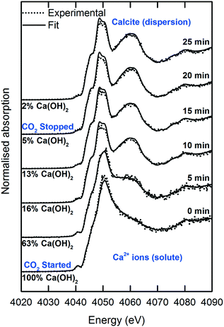 | ||
| Fig. 8 Time-dependent Ca K-edge XANES spectra of the operando carbonation of 18.8 mM Ca(OH)2 using the sessile droplet configuration. | ||
The signal-to-noise quality of the XANES spectra is better in the sessile droplet setup compared to that from the liquid-jet setup. This is reflected in the larger error bars in the LCF results for the liquid-jet system compared with the droplet system (Fig. 7 and 9, respectively). Even though the dwell time for the measurements of the liquid-jet spectra was longer compared to that for the sessile droplet spectra, pulsation of the jet flow and suspended solid particles passing through the X-ray beam contributed to lowering the signal-to-noise ratio of the liquid-jet spectra. In contrast, the sessile droplet was initially a clear solution, which remained relatively stable in its position, aside from the gradual shrinkage in the droplet due to evaporation.
It should be noted that the initial Ca(OH)2 concentration used in the droplet and the liquid-jet experiments was different (Fig. 10). The solution in the droplet experiment was a saturated solution with 18.8 mM Ca(OH)2, i.e., a clear solution containing only dissolved Ca2+ ions and no dispersed Ca(OH)2 particulates. For the liquid-jet experiment, we used a 75 mM Ca(OH)2 dispersion, representing a saturated Ca2+ solution in contact with Ca(OH)2 dispersion. Therefore, the initial spectra for the two systems were different since the spectral features of Ca2+ ions and Ca(OH)2 are different (Fig. 10).
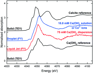 | ||
| Fig. 10 The reference Ca K-edge XANES spectra. The sessile droplet spectrum was averaged over 13 spectra. The liquid-jet spectrum was averaged over 17 spectra. | ||
In addition, the calcite formation profile appeared to be different for the liquid-jet and droplet systems (Fig. 7 and 9, respectively). The liquid-jet system appeared to have an upward convex calcite profile; whereas, the sessile droplet system had a downward convex calcite profile. The difference was particularly obvious after five minutes of introducing CO2 into the system, where 37% of the reactant was converted to calcite in the droplet system. On the other hand, in the liquid-jet configuration, only 10% of the reactant was converted to calcite. The different calcite formation profiles observed in the two systems may be due to the different mixing behaviors in both systems. In the droplet configuration, insoluble calcite particles formed at the gas–liquid interface and remained suspended at the surface of the droplet by interfacial tension. In contrast, in the liquid-jet configuration, the calcite particles formed were mixed with the dispersion samples. Considering that FY detection is sensitive towards the top hundred μm layer of a sample and that calcite accumulated at the surface of the droplet but not at the surface of liquid-jet, the droplet system appeared to have a higher concentration of calcite than the liquid-jet system.
In addition, the calcite formation profile may be influenced by the different reaction pathways in both the droplet and liquid-jet systems. In the saturated solution in the droplet system, calcite was formed directly from Ca2+ ions and the reaction was limited by the diffusion of CO2. On the other hand, in the liquid-jet system containing dissolved Ca2+ ions and Ca(OH)2 dispersion, an additional Ca(OH)2 dissolution step was involved, and thus the reaction may be limited by both the Ca(OH)2 dissolution rate and CO2 diffusion.
4. Discussion
Prior to carbonation, the XANES spectrum of the soluble Ca2+ species (as exemplified by the saturated Ca(OH)2 solution in the droplet configuration in Fig. 8 and 10) is reminiscent of the spectra of Ca2+ species with low symmetry coordination polyhedra, e.g. dilute CaCl2 aqueous solution22 and amorphous CaCO3.23 The spectral characteristics of Ca2+ ions include: (i) the 1s → 3d pre-edge feature at 4040.7 eV, which is a forbidden transition in the octahedral symmetries, but can be present in distorted coordination polyhedra, (ii) the absence of the 1s → 4p shoulder at 4045 eV, and (iii) an intense peak at 4050.5 eV arising from the Ca–O scattering path.22Calcite has more distinctive spectral features compared to Ca2+ ions due to the ordered coordination polyhedra in the calcite crystal. The spectrum of calcite is readily distinguishable from the spectra of the other anhydrous polymorphs of CaCO3, namely aragonite and vaterite.23–25 The spectral characteristics of calcite include: (i) a 1s → 3d split pre-edge peak at 4040.7 eV, which arises from admixing of p-states with the 3d final state, (ii) a 1s → 4p shoulder at 4045 eV and (iii) intense peaks at 4050 and 4060 eV. Previous studies on the formation of CaCO3 from aqueous Ca(OH)2 systems mostly focused on the modification of the morphology of calcite particles by varying the reaction conditions.26 It should be noted that the polymorphic form of the CaCO3 products formed is known to be a complex function of pH, concentration, temperature, stirring rate, and the type and concentration of additives and reactants.27
A comparison of the capabilities and limitations of the droplet and liquid-jet configurations is given in Table 1. We demonstrated that the liquid-jet configuration allows handling of a multiphase gas–liquid–solid system. This capability was achieved by having a relatively large bore diameter of 0.8 mm for the tubing that delivered the jet and by flowing the dispersion at a suitably high flow rate of 370 mL min−1. These features helped to minimize pulsation of the liquid-jet stream propagated from the mechanical movement of the peristaltic pump rollers and minimize the probability of blockage of the sampling loop by the dispersion. When the composition of the solution or dispersion is changed, the liquid-jet flow rate and the bore size of the liquid-jet tubing may need to be adjusted accordingly to cater for the change in sample viscosity. Previous studies28,29 described a windowless recycling liquid-jet cell for in situ monitoring the synthesis of nanoparticles at ambient pressure using synchrotron small angle X-ray scattering (SAXS) and XAS techniques. These studies28,29 used hard X-rays, which allowed the straightforward incorporation of a recycling stream at ambient conditions. However, these setups are open systems without a controlled gas environment, which prohibits their use in the tender X-ray range.
| Droplet | Liquid-jet | |
|---|---|---|
| Sampling mode | Static single or double droplet. Minimal mechanical disturbances with a defect-free platform | Dynamic liquid-jet stream. Mechanically agitated in the glass vessel and in the recycling sampling loop |
| Windowless sampling? | Yes | Yes |
| Solvent evaporation | Solvent evaporation will cause the sample to shrink and move out from the beam path | Negligible effects |
| Volume requirement | Small droplet volume (<1 mL) with a small sample reservoir on the 5 mL scale | Sample reservoir in a large reaction vessel in the 500–1000 mL scale with a 30 mL liquid-jet sampling loop |
| Gas-sample interaction | At the droplet gas–liquid interface. There will be gas diffusion gradient across the surface normal direction | In a well-mixed reaction vessel |
| Immiscible solvents | Possible to study but in separated phases, making use of the hanging and sessile double droplet configurations | Possible to study in the form of a well-mixed sample |
| Temperature control | Currently not available but possible | Currently tested up to 60 °C in the reaction vessel |
| Analysis chamber pressure | Ambient pressure only. Limited by mechanical properties of the windows | |
| X-ray energy range | Tender and hard X-rays. Currently, above 3–4 keV but can be adapted for slightly lower energies | |
Droplet cells can be used to measure the early stages of homogeneous nucleation since turbulence and mechanical disturbances are kept minimal in the static configuration. Actually, the droplet configuration is a popular choice for handling liquid samples, particularly where contact of liquid with the wall of a sample vessel or any other surface will affect the outcome of the experiment, e.g. when high energy defects on windows and walls may act as a site for heterogeneous nucleation.9,30 It has been shown that a double droplet configuration provides a free-standing liquid–liquid interface for two immiscible solvents, which served as a defect-free platform for nanoparticle synthesis studies.9,31 This double droplet configuration can incorporate electrochemical control of the liquid–liquid interface to vary reaction rates,8,9 and thus the cell described in the present study will enable such experiment with minimal modification. Acoustic levitation of droplets10 also offers a fully windowless option to study liquids.
Compared to the liquid-jet configuration, the droplet configuration demands a much smaller reservoir volume compared (in the order of several mL vs. few hundred mL). Thus, the droplet cell is ideal in circumstances where sample volumes are limited. It should be noted that a microfluidic flow cell32 only require a small amount of sample in the order of a few hundred μL or mL. The samples are contained within the cell, rendering the microfluidic cell optimal for studying synthesis involving volatile and explosive substances. However, a microfocus X-ray beam may be required to perform XAS measurements in a microfluidic cell.
For the droplet configuration, the aqueous Ca(OH)2 solution was stable over the duration of the XAS measurements. Additional procedures to maintain a stable droplet size was not required. However, when monitoring over an extended duration and when a volatile organic solvent is used, solvent evaporation can be an issue since the droplet may gradually shrink and move out from the beam path. To mitigate this, a slow sample flow rate can be continuously injected using a syringe pump to maintain a constant droplet size. Alternatively, the droplet size can be maintained by saturating the gas environment with solvent vapour using a humidity feedback loop comprising of a humid carrier gas stream, a humidity monitor and a humidity controller.
In the liquid-jet configuration, the dispersion sample in the glass reaction vessel was maintained at 28 °C during the carbonation reaction. The setup can be operated at even higher temperatures and was tested for reactions up to 60 °C. Besides maintaining the operating temperature, the temperature control loop helped to prevent sample overheating during the exothermic carbonation reaction. For the reaction at 28 °C, temperature loss across the thick-wall Viton tubing was likely to be negligible. The main source of heat loss along the sampling loop would be at the liquid-jet via convective and radiative heat loss, which is also likely to be negligible since the liquid-jet stream had less than 1 millisecond of exposure to the helium environment before intersecting with the position of the X-rays beam. For applications at higher temperature, the flexible tubing and metal structures of the X-ray sampling environment may need to be heated and insulated to ensure minimal heat loss from the sampling loop. Maintaining a constant temperature along the sampling line is important since the reaction kinetics and solubility may be affected by temperature. A decrease in solubility at lower temperatures may lead to solute deposition and blockages in the sample delivery line. For the droplet configuration, the sample can be heated convectively by a stream of hot gas and by adding heating tapes around the metal structures of the droplet sampling environment. To complete the temperature feedback loop, a thermocouple can be implemented in the droplet delivery tubing with a temperature controller.
Both the liquid-jet and sessile droplet cells described in this study were not optimized for reactions at elevated pressures. In that case, a new structure will be necessary, most likely making use of windowed cells to contain a pressurised environment. The glass vessel in the liquid-jet configuration will also need to be replaced by pressure-rated metal reactors.
The cells were initially built with the aim of studying the CaCO3 crystallisation processes in situ using XAS, an area that is yet to be fully explored.33 The capabilities of the liquid-jet and droplet systems were tested at the Ca K-edge; however, the long-term goal is to optimize them further to allow measurements below 4 keV. The polyimide window material and He environment in the cells described in this study were suitable for hard X-rays and part of the tender X-rays region. Only some modifications should be necessary to enable experiments in the softer range, for example P, S and Cl K-edges. The modifications required for accessing softer X-rays include thinner polyimide windows and direct attachment of the FY detector to the He-filled cell since even 1 cm of air significantly attenuates fluorescence signals in the softer energy range. Both cells used in this study are not suitable for transmission measurements at the Ca K-edge because X-rays at 4 keV will be fully absorbed across the 0.8 mm diameter liquid-jet and 6 mm diameter droplet.
The liquid-jet and droplet configurations described in this study can be either directly used or adapted for applications in nucleation, crystallization, complex nanoparticle synthesis and photocatalytic reactions. In this study, we demonstrated their applications in the carbonation of aqueous Ca(OH)2 systems. Some other examples of in situ studies on calcium systems include SAXS study of the formation of CaCO3 using a recycling liquid-jet cell34 and XANES study of the formation of calcium phosphate clusters using a static cell.35 Using these sample environments, the interdependence of the different stages of particle formation (pre-nucleation, early nucleation and growth) with reaction conditions and solvents can be studied. Since both the liquid-jet and sessile droplet configurations are constructed for operation at atmospheric pressure, there may be limited scope for operando applications in the some industrial processes and catalytic reactions that require operation at elevated pressure.
Conclusions
We constructed a versatile cell that permits the windowless probing of dynamic processes in liquid dispersions and solutions by XAS, notably including the photon energy range in the tender X-ray range above 4 keV and in the hard X-ray range. The cell can be operated in the liquid-jet or droplet configuration, while also allowing mounting of solid samples. Operando time-dependent measurements during the carbonation of aqueous Ca(OH)2 were demonstrated for both the liquid-jet and droplet cell operations. The Ca K-edge XAS data quantified the composition of the reaction system during the transformation of Ca(OH)2 to calcite in the presence of CO2. These gas–solid–liquid studies also demonstrated the capability of the cells to monitor multiphase systems. For liquid-jet operation, recycling minimized the loss of sample volume. Therefore, this system opens an inexpensive avenue to study multiphase systems, widening the applications of operando XAS to study complex colloidal systems, including viscous Newtonian and non-Newtonian systems and heterogeneous nucleation and crystallization processes.Conflicts of interest
There are no conflicts to declare.Acknowledgements
The authors thank Diamond Light Source for the award of beamtime at B18 under proposal number SP15850-1 and SP14673-1. The authors would also like to thank Professor Peter Heggs, University of Leeds for the constructive discussion on temperature control. TAK gratefully acknowledges the financial support from Infineum UK and EPSRC Centre for Doctoral Training in Complex Particulate Products and Processes (EP/L015285/1). SLMS would like to thank Royal Academy of Engineering, Diamond and Infineum UK for support of the Bragg Centenary chair. SYC is grateful to Infineum UK, AstraZeneca, Diamond Light Source for the financial support. All data supporting this study are provided either in the results section of this paper or in the ESI† accompanying it.References
- J. A. V. Bokhoven and C. Lamberti, X-ray Absorption and X-ray Emission Spectroscopy: Theory and Applications, John Wiley & Sons, 2016 Search PubMed.
- J.-D. Grunwaldt, M. Ramin, M. Rohr, A. Michailovski, G. R. Patzke and A. Baiker, Rev. Sci. Instrum., 2005, 76, 054104 CrossRef.
- J. L. Fulton, J. G. Darab and M. M. Hoffmann, Rev. Sci. Instrum., 2001, 72, 2117–2122 CrossRef CAS.
- R. Qiao, Y. Xia, X. Feng, J. Macdougall, J. Pepper, K. Armitage, J. Borsos, K. G. Knauss, N. Lee, A. Allézy, B. Gilbert, A. A. MacDowell, Y.-S. Liu, P.-A. Glans, X. Sun, W. Chao and J. Guo, Rev. Sci. Instrum., 2018, 89, 013114 CrossRef PubMed.
- Y. Ye, A. Kawase, M.-K. Song, B. Feng, Y.-S. Liu, M. Marcus, J. Feng, E. Cairns, J. Guo and J. Zhu, Nanomaterials, 2016, 6, 14 CrossRef PubMed.
- S. Schmidt, S. Sallard, C. Borca, T. Huthwelker, P. Novák and C. Villevieille, Chem. Commun., 2018, 54, 4939–4942 RSC.
- L. N. Nchari, G. A. Hembury, A. M. Beesley, D. J. Meehan, N. Tsapatsaris, M. Hudson, M. Thomason and S. L. M. Schroeder, J. Phys.: Conf. Ser., 2009, 190, 0121556 CrossRef.
- S. G. Booth, A. Uehara, S. Y. Chang, J. F. W. Mosselmans, S. L. M. Schroeder and R. A. W. Dryfe, J. Phys. Chem. C, 2015, 119, 16785–16792 CrossRef CAS.
- Y. Gründer, J. F. W. Mosselmans, S. L. M. Schroeder and R. A. W. Dryfe, J. Phys. Chem. C, 2013, 117, 5765–5773 CrossRef.
- S. E. Wolf, J. Leiterer, M. Kappl, F. Emmerling and W. Tremel, J. Am. Chem. Soc., 2008, 130, 12342–12347 CrossRef CAS PubMed.
- M. L. Schlossman, D. M. Mitrinovic, Z. Zhang, M. Li and Z. Huang, Synchrotron Radiat. News, 1999, 12, 53–58 CrossRef.
- I. Watanabe, H. Tanida, S. Kawauchi, M. Harada and M. Nomura, Rev. Sci. Instrum., 1997, 68, 3307–3311 CrossRef CAS.
- J. Polte, R. Erler, A. F. Thunemann, F. Emmerling and R. Kraehnert, Chem. Commun., 2010, 46, 9209–9211 RSC.
- J. W. Smith and R. J. Saykally, Chem. Rev., 2017, 117, 13909–13934 CrossRef CAS PubMed.
- N. Huse, T. K. Kim, L. Jamula, J. K. McCusker, F. M. F. de Groot and R. W. Schoenlein, J. Am. Chem. Soc., 2010, 132, 6809–6816 CrossRef CAS PubMed.
- S. Schreck, G. Gavrila, C. Weniger and P. Wernet, Rev. Sci. Instrum., 2011, 82, 103101 CrossRef PubMed.
- C. Schwanke, R. Golnak, J. Xiao and K. M. Lange, Rev. Sci. Instrum., 2014, 85, 103120 CrossRef CAS PubMed.
- C. Schwanke, L. Xi and K. M. Lange, J. Synchrotron Radiat., 2016, 23, 1390–1394 CrossRef CAS PubMed.
- H. Yuzawa, M. Nagasaka and N. Kosugi, J. Phys. Chem. C, 2015, 119, 7738–7745 CrossRef CAS.
- A. J. Dent, G. Cibin, S. Ramos, A. D. Smith, S. M. Scott, L. Varandas, M. R. Pearson, N. A. Krumpa, C. P. Jones and P. E. Robbins, J. Phys.: Conf. Ser., 2009, 190, 012039 CrossRef.
- B. Ravel and M. Newville, J. Synchrotron Radiat., 2005, 12, 537–541 CrossRef CAS PubMed.
- J. L. Fulton, S. M. Heald, Y. S. Badyal and J. M. Simonson, J. Phys. Chem. A, 2003, 107, 4688–4696 CrossRef CAS.
- R. S. K. Lam, J. M. Charnock, A. Lennie and F. C. Meldrum, CrystEngComm, 2007, 9, 1226–1236 RSC.
- L. Brinza, P. F. Schofield, M. E. Hodson, S. Weller, K. Ignatyev, K. Geraki, P. D. Quinn and J. F. W. Mosselmans, J. Synchrotron Radiat., 2014, 21, 235–241 CrossRef CAS PubMed.
- Y. Politi, Y. Levi-Kalisman, S. Raz, F. Wilt, L. Addadi, S. Weiner and I. Sagi, Adv. Funct. Mater., 2006, 16, 1289–1298 CrossRef CAS.
- M. Ukrainczyk, J. Kontrec, V. Babić-Ivančić, L. Brečević and D. Kralj, Powder Technol., 2007, 171, 192–199 CrossRef CAS.
- R. Chang, S. Kim, S. Lee, S. Choi, M. Kim and Y. Park, Front. Energy Res., 2017, 5, 17 CrossRef.
- J. Polte, T. T. Ahner, F. Delissen, S. Sokolov, F. Emmerling, A. F. Thünemann and R. Kraehnert, J. Am. Chem. Soc., 2010, 132, 1296–1301 CrossRef CAS PubMed.
- K. M. Lange, A. Kothe and E. F. Aziz, Phys. Chem. Chem. Phys., 2012, 14, 5331–5338 RSC.
- Y. Ohkubo, T. Nakagawa, S. Seino, J. Kugai, T. A. Yamamoto, H. Nitani and Y. Niwa, J. Synchrotron Radiat., 2014, 21, 1148–1152 CrossRef CAS PubMed.
- S. G. Booth, A. Uehara, S.-Y. Chang, J. F. W. Mosselmans, S. L. M. Schroeder and R. A. W. Dryfe, J. Phys. Chem. C, 2015, 119, 16785–16792 CrossRef CAS.
- K. S. Elvira, X. C. i Solvas, R. C. R. Wootton and A. J. deMello, Nat. Chem., 2013, 5, 905–915 CrossRef CAS PubMed.
- A. Dey, G. de With and N. A. J. M. Sommerdijk, Chem. Soc. Rev., 2010, 39, 397–409 RSC.
- Y. Chao, O. Horner, P. Vallée, F. Meneau, O. Alos-Ramos, F. Hui, M. Turmine, H. Perrot and J. Lédion, Langmuir, 2014, 30, 3303–3309 CrossRef CAS PubMed.
- Q. Zhang, Y. Jiang, B.-D. Gou, J. Huang, Y.-X. Gao, J.-T. Zhao, L. Zheng, Y.-D. Zhao, T.-L. Zhang and K. Wang, Cryst. Growth Des., 2015, 15, 2204–2210 CrossRef CAS.
Footnote |
| † Electronic supplementary information (ESI) available. See DOI: 10.1039/c8re00207j |
| This journal is © The Royal Society of Chemistry 2019 |

