
 Open Access Article
 This Open Access Article is licensed under a
 Creative Commons Attribution 3.0 Unported Licence
Determination of styrene hydrogenation surface kinetics through detailed simulation of the hydrogen uptake curve†
Ilias
Stamatiou
 a,
Colin
Brennan
b and
Frans L.
Muller
*a
a,
Colin
Brennan
b and
Frans L.
Muller
*a
aSchool of Chemical & Process Engineering, University of Leeds, LS2 9JT, UK. E-mail: F.L.Muller@leeds.ac.uk
bSyngenta, Jeallot's Hill International Research Centre, Berkshire RG42 6EY, UK
First published on 10th July 2019
Abstract
The styrene hydrogenation over Pd/C in a three-phase dead-end stirred tank reactor has been simulated. The mass transfer coefficients were calculated based on experimental data. The fast intrinsic reaction kinetics did not allow the effects of the gas–liquid and liquid–solid mass transfer to be ignored. A rigorous model is described which includes all mass transfer steps with a Langmuir–Hinshelwood model of the surface chemical reaction. The adsorption constants of hydrogen, styrene and ethylbenzene on catalyst active sites were estimated from a single experimental reaction profile. The parameterised model was validated against 6 further sets of experimental data which were not included in the parameters' estimation procedure. Results indicate the ethylbenzene, styrene and hydrogen adsorption to have an equilibrium constant of 148.34 L mol−1, 847.72 L mol−1 and 19![[thin space (1/6-em)]](https://www.rsc.org/images/entities/char_2009.gif) 984 L mol−1, respectively. The intrinsic rate constant for the 4.63% Pd/C catalyst is 0.0542 mol gcat−1 s or 1.17 mol gPd−1 s−1. This work demonstrates that the analysis of the whole hydrogenation reaction profile in combination with detailed mass transfer resistance evaluation can provide fundamental system properties.
984 L mol−1, respectively. The intrinsic rate constant for the 4.63% Pd/C catalyst is 0.0542 mol gcat−1 s or 1.17 mol gPd−1 s−1. This work demonstrates that the analysis of the whole hydrogenation reaction profile in combination with detailed mass transfer resistance evaluation can provide fundamental system properties.
1. Introduction
It is well-known that gas–liquid–solid three-phase reactors play an important role in the chemical industry. The pharmaceutical and fine chemical industries employ batch or semi-batch mechanically agitated slurry reactors for the production of high additional value products as they are more versatile, and therefore, more suitable for multi-purpose plants.1,2A three-phase reaction is a complicated combination of physical and chemical processes (Fig. 1). The three-phase reaction involves hydrogen mass transfer from gas to the bulk of the liquid phase, substrate and hydrogen mass transfer from the bulk to the surface of the solid phase and pore diffusion within the solid phase and finally transfer and adsorption onto the catalytic metal nanoparticles dispersed over the pore surface.2–4 The chemical reaction occurs on the nanoparticles: adsorbed reactants migrate to active sites where the reaction activation energy is lowest. Each of the mass transfer processes and the chemical reaction affect the overall rate to different extents. In particular, when a fast chemical reaction takes place the mass transfer is likely to affect strongly the overall rate.4
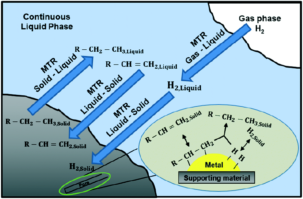 | ||
| Fig. 1 Process scheme of styrene hydrogenation in a batch stirred tank reactor. The process scheme shows the phases (zones of relatively constant composition), the key components in these phases, and the main transport and reaction pathways. | ||
The objective of this work is to develop a model to describe the heterogeneous hydrogenation of styrene over a commercial Pd/C in a semi-batch dead-end stirred tank reactor and approximate the surface kinetics of the reaction by comparing the simulated concentration profile of styrene to experimental data for which the experimental methodology, material details, and results are in the work of Stamatiou and Muller.4
2. Mathematical model
Mass transfer
Fig. 1 describes the three-phase hydrogenation of styrene to produce ethylbenzene in a batch stirred tank reactor. Mass transfer is achieved by two mechanisms: diffusion and convection. To describe mass transfer through interfaces, the Danckwerts surface renewal model is used since the fluid flow near the interfaces is slow, due to non-slip boundary conditions, and diffusion becomes the dominating mass transfer mechanism.5The Danckwerts surface renewal model of mass transfer relates the mass transfer from an interface into a fluid by:
 | (1) |
The mass transfer rate (MTR) is given in units of mol s−1 m−3 of the liquid, ki is the observed mass transfer constant (m s−1), αi is the interfacial area available for mass transfer and (Ci − Cb) is the concentration difference between the interface and the averaged fluid, or the bulk concentration (mol per unit volume liquid). Therefore, the mass transfer rates in the different locations are expressed in eqn (2)–(4).
The interfacial area, ag, which is available for mass transfer from the gas to liquid phase, is created by the external surface area of the bubbles, which are dispersed in the continuous liquid phase by means of agitation, and it has units of m2 m−3 liquid. The interfacial area, αS, which is available for mass transfer from the liquid to solid phase, is created by the external area of the solids (catalyst supporting material), which are suspended in the continuous liquid phase by means of agitation, and it has units of m2 gcat−1.
1. Mass transfer at the gas–liquid interface – gas side
 | (2) |
2. Mass transfer at the gas–liquid interface – liquid side
| MTRH2,i→L = kL·ag·(CH2,i − CH2,L) | (3) |
3. Mass transfer at the liquid–solid interface
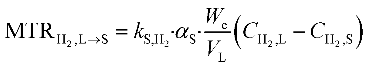 | (4) |
In the case of pure hydrogen or slightly soluble gases, it is unlikely that the adsorption of H2 affects the overall rate. Therefore, it is neglected and the concentration of H2 at the gas–liquid interface is considered to be in equilibrium with the gas phase pressure based on Henry's law6,7 which is given by eqn (5), where HE is the Henry constant.
| PH2 = HE·CH2,i | (5) |
The internal mass transfer due to the pore structure of the catalyst may be modelled using the Thiele modulus. In the course of this study, the internal mass transfer is neglected because of the use of a fine powder catalyst with a diameter of 20 μm4.
Surface reaction
To describe mathematically the mechanism of the surface reaction between styrene and hydrogen, we adopt the Langmuir–Hinshelwood model. We use a commercial palladium on carbon catalyst, obtained from Johnson Matthey (type 87L, Pd content based on ICP-MS: 4.63%), where hydrogen is dissociatively chemisorbed.8–12 We assume that styrene and hydrogen compete for the same sites. The reaction mechanism conforms to a Horiuti–Polanyi model and is described by the elementary steps which are presented in Table 1, (□ represents active catalyst sites) (Fig. 2).| H2,S + □ □ |

|
2·H − □ |

|
(s1) |
| StS + □ |

|
St − □ |

|
(s2) |
| StS − □ + H − □ |

|
I − □ + □ |

|
(s3) |
| I − □ + H − □ |

|
EB − □ + □ |
|
(s4) |
| EBS + □ |

|
EB − □ |
|
(s5) |
 | ||
| Fig. 2 Chemical reaction scheme of styrene (St) hydrogenation to ethylbenzene (EB). | ||
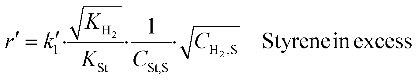
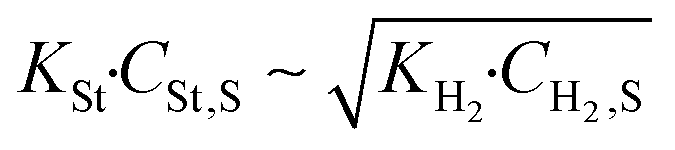
Steps s2 and s5 describe the adsorption/desorption of styrene and ethylbenzene, respectively, while step s1 represents the dissociative adsorption of hydrogen. In steps s3 and s4, we have assumed that styrene is consecutively hydrogenated by two different hydrogen atoms which have been dissociated on the active sites of the catalyst. The first adsorbed hydrogen atom is added to the adsorbed styrene molecule, in step s3, producing the semi-hydrogenated intermediate, I, which afterwards reacts with the second adsorbed hydrogen to produce an adsorbed ethylbenzene molecule (s4). The linear dependency of the reaction rate on the square root of hydrogen concentration (Fig. 3) indicates that the first hydrogen addition (s3) is the rate-determining step. The surface reaction rate, r′, is given by eqn (6).
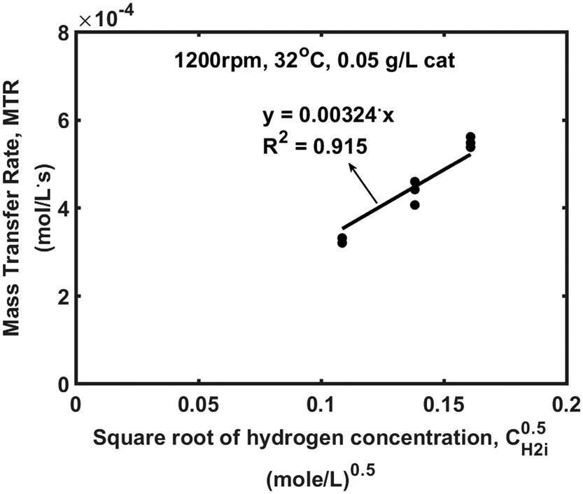 | ||
| Fig. 3 Mass transfer rate against the square root of hydrogen concentration. | ||

| (6) |
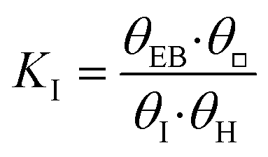
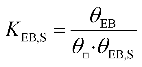
To eliminate the fractional surface coverages of styrene and hydrogen from eqn (6), θSt and θH, we use the expressions of equilibrium constants and the mass balance of the active sites (eqn (7)). The fractional surface coverage of the semi-hydrogenated radical, θI, is assumed to be negligible compared to the surface coverages of hydrogen, styrene and ethylbenzene. Finally, the surface reaction of styrene hydrogenation is described by eqn (9).
| θSt + θH + θEth + θ□ = 1 | (7) |
 | (8) |
 | (9) |
 | (10) |
 | (11) |
Material balance of species in the reactor
The semi-batch reactor operates in the dead-end mode; all materials remain in the reactor and hydrogen gas is supplied continuously to the reactor with the flow rate controlled so as to keep the reactor pressure constant. Without agitation, there is no appreciable gas–liquid mass transfer so time zero (t = 0) coincides with the switching on of the agitator. The experimental data set is analysed assuming (i) any hydrogen passing through the mass flow controller is being consumed by the reaction and (ii) the quantities of styrene and ethylbenzene associated with the catalyst phase are small compared to the quantity in the liquid bulk.We have written the material balances of the species in the three different phases: (i) the hydrogen gas phase with volume VG, (ii) the bulk liquid phase with volume VL and (iii) a small volume associated with the catalyst VSL. Conventionally, this last volume is chosen to be zero, essentially assuming that the concentrations in the catalyst instantaneously reach their dynamic equilibrium (so dCSt,S/dt and dCEB,S/dt = 0 at all times). We choose not to make this assumption, and arbitrarily set the volume of the liquid associated with the catalyst to the volume of particles in the reaction mixture, so as to observe the timescale over which the dynamic equilibrium is reached. The volume of particles in the reaction mixture was estimated for solid spheres and by using the mean particle diameter and particle density found in Stamatiou and Muller.4
We assume that the concentration of each material in this volume can be represented by a single variable and that the concentrations of styrene, ethylbenzene and hydrogen CSt,S, CEB,S and CH2,S, respectively, are in their adsorption equilibrium (step s1, s2 and s5 in Table 1).
We have written the material balances of the species in the three different phases. Hydrogen is present in gas phase, in bulk liquid phase, where it is dissolved, and at the outer surface of the catalyst support. The concentration of hydrogen at the outer surface of the catalyst support, CH2,S, is in equilibrium with the amount of hydrogen which is dissociatively adsorbed onto catalyst active sites.
The material balances of each species in each phase for the semi-batch are described below in eqn (12)–(18).
Hydrogen

| (12) |
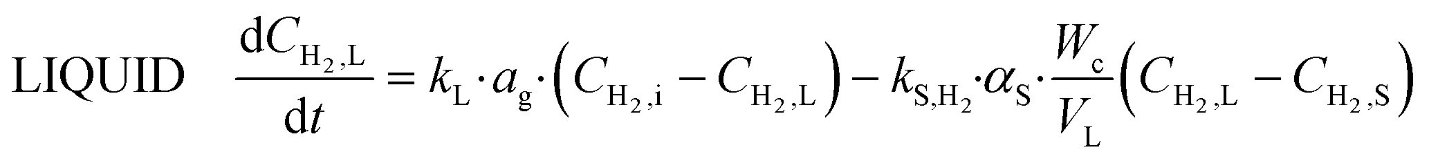
| (13) |

| (14) |
Styrene

| (15) |

| (16) |
Ethylbenzene

| (17) |
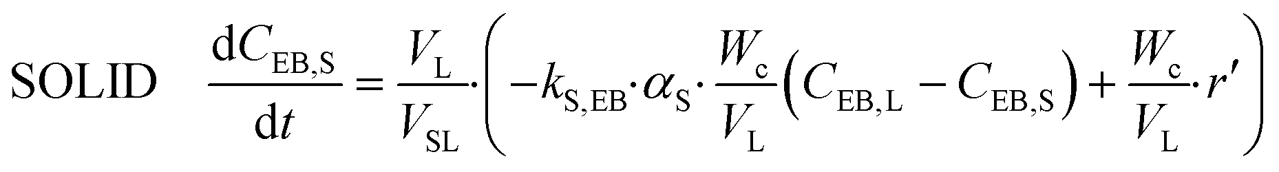
| (18) |
3. Results and discussion
The reactor model is described by the differential equations eqn (15)–(21). To overcome the stiffness of the reactor's model, the ODE15s MATLAB solver was used for simulating the progression of concentrations of species over time in the reactor. Seven different experiments were used under various agitation speeds, catalyst concentrations and pressures, each one repeated three times. All experiments were conducted at 32 °C; hence, temperature effects are not included in the model. One experiment was used for estimating the model parameters (training data set), which are described below, while the other six experiments were used to validate the model (validation data) since their data which were not used in the parameter estimation procedure which is described below.The model consists of eight different parameters; four are related to the external mass transfer, three are related to the adsorption/desorption of the molecules on the catalyst active sites, and one is related to the intrinsic chemical reaction kinetics. The adsorption constants of styrene, KSt, hydrogen, KH2, and ethylbenzene, KEB, and the intrinsic reaction rate constant,  , were estimated by using the MATLAB Global Search algorithm to fit the numerical solution of the reactor model described by the differential equations eqn (12)–(18) to the experimentally observed styrene concentration profile in experiment 1. The numerical solution was obtained using the implicit ODE15s MATLAB solver, which is capable of handling the stiffness of the reactor's model. The resulting fitting parameters were then validated using experiments 2–7 (Table 2), which were not used in the fitting procedure. It is assumed that the external mass transfer parameters do not affect the surface reaction kinetics.
| Training | Validation | |||||||
|---|---|---|---|---|---|---|---|---|
| Exp. 1 | Exp. 2 | Exp. 3 | Exp. 4 | Exp. 5 | Exp. 6 | Exp. 7 | ||
| N | (rpm) | 1200 | 1200 | 1000 | 1000 | 700 | 500 | 400 |
| P | (Bara) | 3 | 7 | 3 | 5 | 3 | 3 | 3 |
| T | (°C) | 32 | 32 | 32 | 32 | 32 | 32 | 32 |
| C cat. | (g L−1) | 0.05 | 0.05 | 0.1 | 0.1 | 0.2 | 0.085 | 0.125 |
| k L a g | (s−1) | 0.0873 | 0.0873 | 0.1094 | 0.1094 | 0.0710 | 0.0558 | 0.0299 |
| ±95% C. I | 0.0216 | 0.0216 | 0.0099 | 0.0099 | 0.0050 | 0.0021 | 0.0004 | |
| k S,H2 α S | (L s−1 g−1) | 2.85 | 2.82 | 1.5530 | 1.5530 | 0.6327 | 0.9760 | 0.5837 |
| 95% C. I | 1.95 | 1.95 | 0.7745 | 0.7745 | 0.1721 | 0.2782 | 0.0838 | |
| k S,St α S | (L s−1 g−1) | 1.14 | 1.14 | 0.6212 | 0.6212 | 0.2531 | 0.3904 | 0.2335 |
| ±95% C. I | 0.78 | 0.78 | 0.3098 | 0.3098 | 0.0688 | 0.1113 | 0.0335 | |
| k S,EB α S | (L s−1 g−1) | 1.20 | 1.20 | 0.6523 | 0.6523 | 0.2657 | 0.4099 | 0.2452 |
| ±95% C. I | 0.82 | 0.82 | 0.3253 | 0.3253 | 0.0723 | 0.1168 | 0.0352 | |
The styrene concentration profile was calculated by using the accumulative consumption curve of hydrogen and it is given by eqn (19).
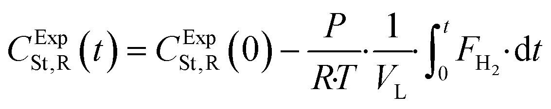 | (19) |
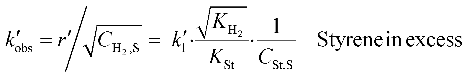
The data for calculating the mass transfer coefficients of hydrogen were found in the work of Stamatiou and Muller,4 while the liquid–solid mass transfer coefficients of styrene and ethylbenzene were correlated to the liquid–solid mass transfer coefficient of hydrogen based on the values of the square root of their diffusion coefficients in methanol, since the surface renewal model suggests that  . The values of mass transfer coefficients have been calculated using the data which correspond to periods for which styrene is in a large excess. Therefore, the observed chemical reaction constant is given by eqn (11). All the mass transfer coefficients and the experimental conditions are summarised in Table 2.
Objective function and constrains
The objective function minimised is the sum of squared errors between the experimental and simulated concentrations of styrene under the conditions of experiment 1, CExpSt,L and CSimSt,L, respectively, and it is described by eqn (20).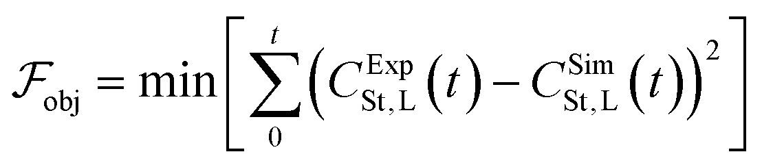 | (20) |
There are two sets of constrains which the optimum solution needs not to violate; the first set is associated with the observed chemical reaction constant and its 95% confidence intervals, while the second comes from the Langmuir–Hinshelwood model and the competition between hydrogen and styrene molecules for active sites.
Regarding the first set of constrains, the observed chemical reaction constant,  , and its 95% confidence intervals were calculated from the data in the work of Stamatiou and Muller.4 The
  needs to lie between 0.059
  and 0.103
  . Taking into account eqn (11), the constraints are given by eqn (21).
 | (21) |
Regarding the second set of constrains, the concentration profile of styrene is divided into two different regimes (Fig. 4). Initially, the styrene consumption rate is constant and the styrene concentration decreases linearly over time indicating that the reaction rate is independent of the styrene concentration. Although the hydrogen concentration is kept constant for the whole course of the reaction, after a threshold value of the styrene concentration, a second regime is developed where the styrene consumption rate decreases over time indicating that the reaction order of styrene has changed from zero to first order.
 | ||
| Fig. 4 Reactant concentration profiles and consumption rate over time; blue dots indicate the styrene concentration in bulk liquid phase, and blue squares indicate the hydrogen concentration in the gas–liquid interface calculated by Henry's law. | ||
The threshold value of styrene concentration depends on the association between the catalyst and the molecules of hydrogen and styrene. From the Langmuir–Hinshelwood model, an indication of this association is given by the adsorption constants.
The second set of constrains comes from the equality (eqn (23)) which defines the regime change. From Fig. 4 the concentrations of styrene and hydrogen at the point where the regime changes were found to be 0.024 mol L−1 and 0.0118 mol L−1, respectively.
Table 3 summarises the different regimes that a heterogeneous reaction can develop according to the Langmuir–Hinshelwood model. The regime change occurs when the styrene and hydrogen terms are almost equal and if the two terms are comparable, both reactants affect the reaction rate.

|
Styrene in excess. Reaction rate independent of styrene concentration | Eqn (22) |

|
Regime change | Eqn (23) |
|
Both reactants affect the reaction rate | Eqn (24) |
Substituting the concentration in eqn (23), the adsorption constant of styrene needs to be almost 4.5 times the square root of the adsorption constant of hydrogen – indicating that active sites adsorb preferably hydrogen against styrene – in order to change the reaction order when the styrene concentration is 0.024 mol L−1 and the hydrogen concentration is 0.0118 mol L−1. Based on this, eqn (26) describes the second set of constrains which the optimum solution needs not to violate.
 | (25) |
 | (26) |
The GlobalSearch built-in MATLAB algorithm was used for the minimisation of the objective function which is given by eqn (20). The algorithm needs an initial guess for the independent variables (KSt, KH2, KEB and  ) and the bounds of each variable. The bounds specify the search space. Due to the lack of any sense about where the constants might lie, the algorithm run with different sets of initial guesses and different sets of bounds. Tables 5 and 4 summarise the initial guesses and bounds which were used in seven different runs.
| Trial | K H2 (L mol−1) | K St (L mol−1) | K Eth (L mol−1) |
|
|---|---|---|---|---|
| 1–2 | 100 | 100 | 100 | 100 |
| 3 | 7000 | 1000 | 100 | 0.01 |
| 4 | 12500 |
1550 | 250 | 0.01 |
| 5 | 15000 |
1200 | 250 | 0.01 |
| 6 | 17500 |
950 | 250 | 0.01 |
| Trial |
K
H2 (Lmol−1) |
K St (L mol−1) | K EB (L mol−1) |
|
||||
|---|---|---|---|---|---|---|---|---|
| LB | UB | LB | UB | LB | UB | LB | UB | |
| 1 | 10−4 | 104 | 10−4 | 104 | 10−4 | 104 | 10−4 | 104 |
| 2 | 10−1 | 104 | 10−1 | 103 | 10−1 | 5 × 10² | 10−3 | 10−1 |
| 3 | 103 | 1.5 × 10⁴ | 10 | 2 × 10³ | 10−1 | 5 × 10² | 10−3 | 10−1 |
| 4 | 5 × 10³ | 2 × 10⁴ | 102 | 3 × 10³ | 10−1 | 5 × 10² | 10−3 | 10−1 |
| 5 | 104 | 2 × 10³ | 4 × 10² | 2 × 10³ | 10 | 5 × 10² | 10−3 | 10−1 |
| 6 | 1.5 × 10⁴ | 2 × 10⁴ | 4 × 10² | 1.5 × 10³ | 10 | 5 × 10² | 10−3 | 10−1 |
Initially, the algorithm searches for the optimal combination of constants which minimises the objective function in a broad search space, while the initial guesses of the adsorption constants have the same value, case 1. In case 2, the initial guesses are kept the same as in case 1 but the search space shrinks around the optimal solution of case 1. From case 3 to 7, the search space of case i + 1 shrinks around the optimal solution of case i and the initial guess of each parameter is given in the centre of the search space of each parameter. In cases 1 to 3, the algorithm converges to different optimum solutions which improve the minimum of the objective function. But in cases 3 to 7, although the search space shrinks around the optimum solution, the minimum of the objective function did not improve sensibly.
Table 6 summarises the optimum solutions and the minimum values of the objective function for each case, and the lowest value among the minima has been highlighted with bold formatting.
Fig. 5 depicts the experimental and simulated concentration profiles of styrene by substituting the values of the optimum solution which correspond to the lowest objective function value. The ±95% confidence bounds of the concentration profile were simulated using the ±95% confidence intervals of the mass transfer coefficients which are given in Fig. 5.
 | ||
| Fig. 5 Experimental and simulated styrene concentrations. | ||
| Trial 1 | Trial 2 | Trial 3 | Trial 4 | Trial 5 | Trial 6 | ||
|---|---|---|---|---|---|---|---|
| min(Fobj) × 10−4 | 1.778 | 1.090 | 0.986 | 0.953 | 0.8762 | 0.988 | |
| % rel. MSE | 28.33 | 24.61 | 24.43 | 24.52 | 23.70 | 24.86 | |
| K H2 | L mol−1 | 2564 | 9841 | 11472 |
12515 |
19![[thin space (1/6-em)]](https://www.rsc.org/images/entities/b_char_2009.gif) 984 984
|
18678 |
| ±95% C. I | 1210.03 | 171.24 | 2250.80 | 814.10 | 706.18 | 2508.90 | |
| K St | L mol−1 | 293.62 | 591.73 | 636.93 | 669.27 | 847.72 | 798.87 |
| ±95% C. I | 9.48 | 9.15 | 220.86 | 19.83 | 195.75 | 99.43 | |
| K Eth | L mol−1 | 38.95 | 100.45 | 107.08 | 113.20 | 148.34 | 132.66 |
| ±95% C.I | 7.43 | 1.57 | 59.01 | 5.43 | 44.61 | 24.06 | |

|
mol gcat−1 s−1 | 0.0522 | 0.0538 | 0.0528 | 0.0541 | 0.0542 | 0.0528 |
| ±95% C. I | 4.2 × 10⁻⁴ | 2.3 × 10⁻⁴ | 0.0194 | 0.6 × 10⁻⁴ | 0.0098 | 0.0037 | |
When the lower 95% confidence intervals of the mass transfer coefficients are used, the three-phase reaction becomes slower due to the higher mass transfer resistance and the upper confidence bound of the styrene concentration is calculated (red lines in Fig. 5 and 7). On the other hand, when the upper 95% confidence intervals of the mass transfer coefficients are used, the three-phase reaction cannot evolve faster because it is limited by the intrinsic chemical reaction kinetics. This explains why the simulated concentration is not in the middle of the ±95% confidence bounds in Fig. 5. In this case, the lower confidence bound of the styrene concentration profile is calculated (blue lines in Fig. 5 and 7).
To evaluate the effect of the liquid volume associated with the catalyst, VSL, we simulated the reactor in a range of VL/VSL. Apart from the extreme case that the liquid volume associated with the catalyst is equal to the bulk liquid volume, the VL/VSL ratio does not affect the concentration profiles and the estimated adsorption constants. Fig. 6 summarises the concentration profiles of the styrene, ethylbenzene and hydrogen in the different phases and for different VL/VSL. All the profiles correspond to the experimental conditions of experiment 1 (Table 2). When VL/VSL = 102, 105 and 107, the system reaches the dynamic equilibrium in less than 5 s. In the extreme case that the liquid volume associated with the catalyst is equal to the bulk liquid volume, the time required for the dynamic equilibrium to be reached is fifty times more.
 | ||
| Fig. 6 Concentration profiles of St (A1 to A4), EB (B1 to B4) and H2 (C1 to C4) in the different phases for four different VL/VSL. A1, B1 and C1 correspond to the extreme case where VL = VLS; A2, B2 and C2 correspond to VL/VSL = 102; A3, B3 and C3 correspond to VL/VSL = 105; A4, B4 and C4 correspond to VL/VSL = 107. Apart from the extreme case, the system reaches the dynamic equilibrium in less than 5 s. | ||
Model validation
To evaluate how the reactor's model performs under conditions of agitation, pressure and catalyst concentration, which have not been included into the fitting procedure, the model parameterised by fitting trial 5 on experiment 1 (Table 2) was validated against experimental data which were obtained under six additional different sets of experimental conditions, described in Table 2 (experiments 2–7).Fig. 7 shows the experimental and simulated concentration profiles of styrene for each of the six different cases of experimental conditions which change the external mass transfer. Although the surface reaction parameter estimation and the model validation have been accomplished under different external mass transfer conditions, for all the cases of model validation, the experimental data lie inside the ±95% confidence bounds of the simulated concentration profiles. This supports the assumption that the external mass transfer does not affect the surface reaction kinetics and indicates that the analysis of a single hydrogenation reaction profile in combination with detailed mass transfer resistance evaluation can provide fundamental system properties and uncouple the external mass transfer effects from the surface reaction kinetics. Although the mass transfer effects have not been eliminated, due to the fast surface reaction kinetics, the adsorption constants and the intrinsic reaction rate constant can be estimated reliably.
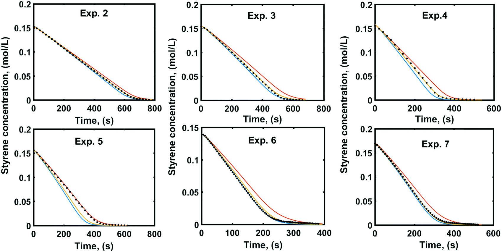 | ||
| Fig. 7 Experimental (dots) and simulated (orange lines) concentration profiles of styrene with the simulated 95% confidence intervals (+95% red lines, −95% blue lines) for model validation. | ||
The confidence bounds of the simulated concentration profiles are calculated based on linear regression models found in the work of Stamatiou and Muller.4
4. Conclusions
The styrene hydrogenation in a three-phase semi-batch stirred tank reactor was simulated by modelling all mass transfer steps, and assuming that the surface chemical reaction follows the Langmuir–Hinshelwood model, hydrogen is dissociatively chemisorbed onto palladium active sites, styrene and hydrogen compete for the same sites and styrene is hydrogenated in two consecutive steps.Curve fitting of three adsorption equilibrium constants, and the rate-limiting reaction on the surface of the metal nanoparticle catalyst to a single reaction profile was shown to provide reliable kinetics. This was validated by prediction of the reaction profiles of three further data sets, each of which remains well within the limits of confidence of previously determined mass transfer constants.
Our work demonstrates that the analysis of the whole hydrogenation reaction profile in combination with detailed mass transfer resistance evaluation can provide fundamental system properties.
Conflicts of interest
There are no conflicts to declare.Acknowledgements
The generous support by Syngenta, EPSRC funding and the University of Leeds is acknowledged.References
- D. M. Roberge, B. Zimmermann, F. Rainone, M. Gottsponer, M. Eyholzer and N. Kockmann, Microreactor Technology and Continuous Processes in the Fine Chemical and Pharmaceutical Industry: Is the Revolution Underway?, Org. Process Res. Dev., 2008, 12, 905–910 CrossRef CAS.
- A. A. C. M. Beenackers and W. P. M. V. Swaaij, Mass transfer in gas-liquid slurry reactors, Chem. Eng. Sci., 1993, 48, 3109–3139 CrossRef CAS.
- E. Dietrich, C. Mathieu, H. Delmas and J. Jenck, Raney-Nichkel catalyzed hydrogenations: g-l mass transfer in gas-induced stirred slurry reactors, Chem. Eng. Sci., 1992, 47, 3597–3604 CrossRef CAS.
- I. K. Stamatiou and F. L. Muller, Determination of mass transfer resistances of fast reactions in three-phase mechanically agitated slurry reactors, AIChE J., 2017, 63, 273–282 CrossRef CAS.
- I. Stamatiou and F. L. Muller, Determination of mass transfer resistances in trickle bed reactors, Chem. Eng. J., 2018 DOI:10.1016/j.cej.2018.08.194.
- G. Biardi and G. Baldi, Three-phase catalytic reactors, Catal. Today, 1999, 52, 223–234 CrossRef CAS.
- M. Herskowitz and J. M. Smith, Trickle Bed Reactors: A Review, AIChE J., 1983, 29, 18 CrossRef.
- P. A. Ramachandran and J. M. Smith, Adsorption of Hydrogen Sulfide in a Slurry Reactor, Ind. Eng. Chem. Fundam., 1978, 17, 17–23 CrossRef CAS.
- R. J. Behm, K. Christmann and G. Ertl, Adsorption of hydrogen on Pd(100), Surf. Sci., 1980, 99, 320–340 CrossRef CAS.
- H. Conrad, G. Ertl and E. E. Latta, Adsorption of hydrogen on palladium single crystal surface, Surf. Sci., 1974, 41, 435–446 CrossRef.
- A. E. Baber, H. L. Tierney, T. J. Lawton and E. C. H. Sykes, An atomic-scale View of palladium alloys and their ability to dissociate molecular hydrogen, ChemCatChem, 2011, 3, 607–614 CrossRef CAS.
- H. Okuyama, W. Siga, N. Takagi, M. Nishijima and T. Aruga, Path and mechanism of hydrogen absorption at Pd(100), Surf. Sci., 1998, 401, 344–354 CrossRef CAS.
Footnote |
| † Electronic supplementary information (ESI) available. See DOI: 10.1039/c8re00132d |
| This journal is © The Royal Society of Chemistry 2019 |