 Open Access Article
A new flexible and ultralight carbon foam/Ti3C2TX MXene hybrid for high-performance electromagnetic wave absorption
Yang Wang ab,
Jian Yang*ab,
Zhaofeng Chen
 c and
Yunlong Hua
aCollege of Materials Science and Engineering, Nanjing Tech University, Nanjing 210009, China. E-mail: yangjian1976@163.com; Tel: +86 13605191742
bJiangsu Collaborative Innovation Center for Advanced Inorganic Function Composites, Nanjing Tech University, Nanjing 210009, China
cJiangsu Collaborative Innovation Center for Advanced Inorganic Function Composites, Nanjing University of Aeronautics and Astronautics, Nanjing 210016, China
First published on 12th December 2019
Abstract
A new ultralight carbon foam/Ti3C2TX (CF/MXene) electromagnetic (EM) absorbing hybrid with three-dimensional network structure was fabricated by vacuum impregnation and freeze-drying process. These hybrids display excellent flexibility and steady compression-resilience properties and also the special three-dimensional structure with ultralow density of only 5–7 mg cm−3 shows higher EM absorption than most foam-based EM absorbers. Studies have shown that the minimum reflection loss of CF/MXene-N2 reaches −45 dB at 8.8 GHz with the Ti3C2TX nanosheets content of 9.8%. In the meanwhile, the effective absorption bandwidth of CF/MXene-N2 can also reach up to 5 GHz (from 6.9 GHz to 11.9 GHz) with the thickness of 4.5 mm. Moreover, the fundamental EM absorption mechanism of CF/MXene hybrids involved to impedance matching, conductive loss and polarization loss is carefully analyzed. Thus, it is expected that the new ultralight carbon foam/Ti3C2TX hybrids with three-dimensional network structure will have great application prospects in the fields of EM absorption.
Introduction
In today's society, with the rapid development of electronic technology, electromagnetic (EM) waves have become a new environmental pollutant and threat, not only influencing the operation of precision instruments and military electronic equipment, but also affecting human health.1–5 Thus, it is urgent to develop new high-performance EM absorbing materials to counteract the hazards.6–9 As an efficient EM absorbing material, three-dimensional (3D) foam can offer ultralow density, abundant pore structure and high specific surface area, which are widely valued in EM absorption.10–15 Reasonable structure and composition optimization are effective ways to improve the electromagnetic parameters and EM wave absorption performance. For example, Dong et al. modified 3D graphene foams by in situ growth of Si3N4 nanowires and SiC nanowires respectively by carbon thermal method, and obtained excellent EM wave absorption effects.13 Ye et al. introduced a novel three-dimensional SiC/carbon-silica aerogel foam, which was fabricated by chemical vapor deposition and the sol–gel method, showing a minimum reflection loss of −18.41 dB at 16.92 GHz with the thickness of 3.65 mm.14 However, the effective absorption bandwidth of this foam was only 1.7 GHz, ranged from 15.80 to 17.52 GHz.The carbon-based material, especially carbon foam (CF) with chemical stability, low density, high porosity and large surface area, is a promising EM wave absorber and carrier, which has attracted a lot of attention in recent years.15–19 Yang et al. investigated the EM absorption properties of mesophase pitch CF by low temperatures treatment.20 It was found out that the pure CF showed weak EM wave absorption performance owing to low dielectric loss. Wang et al. reported a facile template method to prepared an electromagnetic functionalized lightweight CF, which induced the magnetic Fe species in the formation of CF.21 Zhao et al. indicated that the EM absorbing properties of the CF can be significantly improved by introducing Ni nanoparticles into the CF skeleton, owing to the derived interface polarization loss, conductivity loss, weak magnetic loss, and porosity, which have large electromagnetic absorption.22 Therefore, modification of CF is necessary in special fields such as absorbing wave.
As recently reported, Ti3C2TX MXene, as a new type of two-dimensional (2D) materials have attracted tremendous attention in the EM field, owing to their unique 2D laminated structure, ultrahigh electrical conductivity (>4600 S cm−1), active functional groups (–OH, ![[double bond, length as m-dash]](https://www.rsc.org/images/entities/char_e001.gif) O, –F) and native defects.23–27 Typically, Li et al. reported the excellent EM absorption performance of ultralight Ti3C2TX/SiC nws hybrid foams, showing the minimum reflection loss of −55.7 dB and the effective absorption bandwidth of whole X-band at the thickness of 3.5–3.8 mm.28 Qian et al. reported that the EM absorbing performance of ZnO-MXene Ti3C2TX nanocomposite is significantly better than that of pure Ti3C2TX, owing to the unique networks structure and more interfaces.29 Tong et al. found that the Ti3C2TX/PPy hybrids exhibited a minimum reflection loss of −49.2 dB at the thickness of 3.2 mm and an effective absorption bandwidth of 4.9 GHz corresponding to the thickness of 2.0 mm.30 From the above, the Ti3C2TX Mxene hybrids with designed microstructure can enhance the comprehensive performance of electromagnetic wave absorption obviously.
O, –F) and native defects.23–27 Typically, Li et al. reported the excellent EM absorption performance of ultralight Ti3C2TX/SiC nws hybrid foams, showing the minimum reflection loss of −55.7 dB and the effective absorption bandwidth of whole X-band at the thickness of 3.5–3.8 mm.28 Qian et al. reported that the EM absorbing performance of ZnO-MXene Ti3C2TX nanocomposite is significantly better than that of pure Ti3C2TX, owing to the unique networks structure and more interfaces.29 Tong et al. found that the Ti3C2TX/PPy hybrids exhibited a minimum reflection loss of −49.2 dB at the thickness of 3.2 mm and an effective absorption bandwidth of 4.9 GHz corresponding to the thickness of 2.0 mm.30 From the above, the Ti3C2TX Mxene hybrids with designed microstructure can enhance the comprehensive performance of electromagnetic wave absorption obviously.
Herein, we combine the advantages of CF and MXene to prepare a new flexible and ultralight carbon foam/Ti3C2TX MXene hybrids by vacuum impregnation and freeze-drying process, which is simple and efficient for large-scale fabrication. For the hybrids, CF provides a 3D network skeleton with excellent flexibility and steady compression-resilience properties, and the few-layered Ti3C2TX nanosheets are attached to the surface of skeleton uniformly, which can be served as polarizing sites. In addition, the EM absorption performance of carbon foam/Ti3C2TX MXene hybrids and related EM loss mechanisms are fully investigated in the frequency of 2–18 GHz. This work provides the great potential of ultralight carbon foam/Ti3C2TX MXene hybrids as ideal candidates in the field of EM absorption.
Experimental
Preparation of carbon foam and Ti3AlC2 (MAX) powder
Melamine foam (MF; Chengdu Yulong Chemical Co,. Ltd, China) acted as the precursor of CF, a commercially available polymer foam with high porosity of over 99% and low density in the range of 4–8 mg cm−3. The MF was carbonized in vacuum tube furnace at 1100 °C with a heating rate of 3 °C min−1 and holding for about 2 h to get the stable CF sample with a great volume shrinkage. It should be note that when the temperature was heated between 380 °C and 400 °C, MF began to decompose violently, a large number of small molecules overflowed and the network structure became unstable. Therefore, slow heating is beneficial to maintain the stability of the skeleton structure. After that, the density of the obtained CF is about 5 mg cm−3 with extremely high porosity of 99.6%.Ti3AlC2 (MAX) powder was prepared by high-temperature sintering of TiC powder, Ti powder and Al powder (≥99%; Alfa Aesar; USA) after ball milling. First, weigh TiC, Ti powder, Al powder with a molar ratio of 2![[thin space (1/6-em)]](https://www.rsc.org/images/entities/char_2009.gif) :
:![[thin space (1/6-em)]](https://www.rsc.org/images/entities/char_2009.gif) 1
1![[thin space (1/6-em)]](https://www.rsc.org/images/entities/char_2009.gif) :
:![[thin space (1/6-em)]](https://www.rsc.org/images/entities/char_2009.gif) 1, and ball mill for 24 h. Then, the mixed powder was calcined at 1400 °C under an inert atmosphere for 2 hours to obtain Ti3AlC2 block. Finally, the block was manually ground and passed through a 200 mesh sieves to obtain Ti3AlC2 powder as shown in Fig. 1(a). By XRD analysis, the obtained Ti3AlC2 powder contained a small amount of TiC, which can be used in subsequent experiments.
1, and ball mill for 24 h. Then, the mixed powder was calcined at 1400 °C under an inert atmosphere for 2 hours to obtain Ti3AlC2 block. Finally, the block was manually ground and passed through a 200 mesh sieves to obtain Ti3AlC2 powder as shown in Fig. 1(a). By XRD analysis, the obtained Ti3AlC2 powder contained a small amount of TiC, which can be used in subsequent experiments.
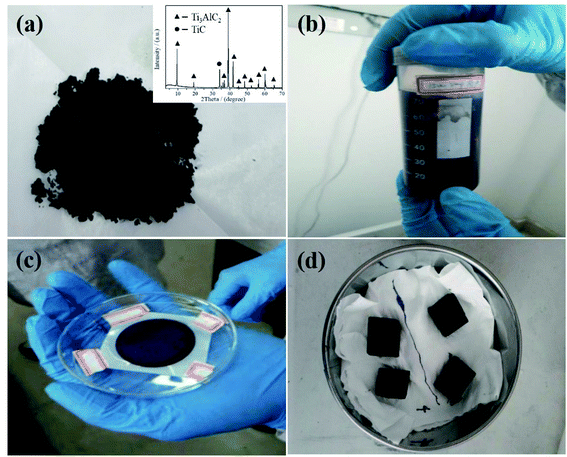 | ||
| Fig. 1 As-prepared Ti3AlC2 MAX powder (a); f-Ti3C2TX solution (b); f-Ti3C2TX film (c); as-prepared CF/MXene and CF samples (d). | ||
Preparation of few-layered Ti3C2TX MXene nanosheets
The few-layered Ti3C2TX nanosheets denoted as f-Ti3C2TX were fabricated via a facile synthesis process.31 First of all, 1 g LiF powder (≥99%; Alfa Aesar; USA) was dissolved in 20 ml HCl solution with a concentration of 9 mol L−1 (Aladdin reagent), followed by stirring for about 10 min until the LiF is completely dissolved at room temperature. After that, slowly pour 1 g Ti3AlC2 MAX powder into the above solution. Then, the solution was stirring for 24 h in a 35 °C water bath with sealed condition. After 24 h, the solution was washed 3 times with deionized water and 2 times with alcohol (Aladdin reagent) by centrifugal treatment (3500 rpm and 5 min for each cycle) until the pH of the solution reached 6–7. Finally, the sediment was subjected to ultrasonic oscillation in deionized water for 1 h and centrifuged for 1 h with 3500 rpm. At the end of the centrifugation, the upper dark green suspension was the f-Ti3C2TX solution as shown in Fig. 1(b). A certain volume of upper dark green suspension was filtered into a film to measure the weight (Fig. 1(c)), which was used to calculate the concentration of the obtained f-Ti3C2TX suspension. According to the calculation, the initial concentration of f-Ti3C2TX suspension was 3 mg ml−1. Subsequently, the f-Ti3C2TX suspension of 3 mg ml−1, 1 mg ml−1 and 0.2 mg ml−1 were separately prepared by adding deionized water to dilute the original f-Ti3C2TX suspension.Preparation of carbon foam/f-Ti3C2TX hybrids
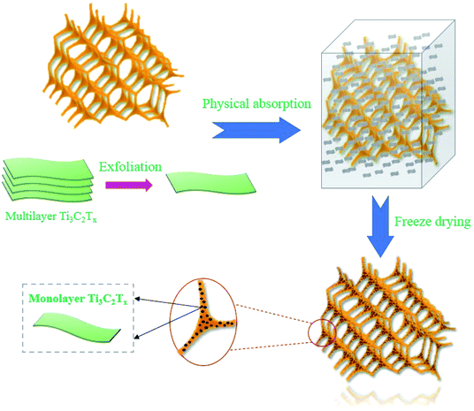
The carbon foam/f-Ti3C2TX hybrids as shown in Fig. 1(d) denoted as CF/MXene were prepared via vacuum impregnation and freeze-drying process. The key fabrication process is shown in Fig. 2. First, four as-prepared CF samples were placed in four vacuum vessels. Three of the CF samples were inhaled with 0.2 mg ml−1, 1 mg ml−1, 3 mg ml−1 f-Ti3C2TX suspensions, respectively. For the contrast, another CF sample was inhaled with deionized water. After that these samples were taken out and put into a beaker. Liquid nitrogen was slowly poured to the beaker and immersed the four samples until the residual solution inside the foam was completely frozen. Then, the samples were transferred an airtight container for vacuum drying under 0.1 Pa pressure. After 24 h, the CF/MXene samples were obtained and named as CF/MXene-N1, CF/MXene-N2, CF/MXene-N3 respectively to the different concentration of impregnation f-Ti3C2TX solution (0.2 mg ml−1, 1 mg ml−1, 3 mg ml−1). Meanwhile, the contents of adsorbed Ti3C2TX nanosheets in CF/MXene-N1, CF/MXene-N2 and CF/MXene-N3 can be expressed by their weight gain rates (the weight of adsorbed Ti3C2TX nanosheets divided by the weight of original carbon foam), which were measured by using a high-precision balance and shown in Fig. 3. The higher the weight gain rate, the more f-Ti3C2TX nanosheets are adsorbed in samples.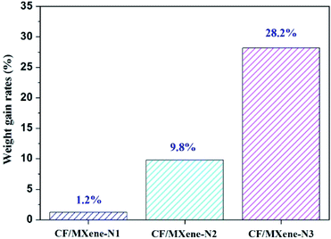 | ||
| Fig. 3 Different contents of adsorbed Ti3C2TX nanosheets in CF/MXene-N1, CF/MXene-N2 and CF/MXene-N3. | ||
Characterization
X-ray diffraction (XRD; SmartLab, Japan) is used to analyze the phase composition of the samples with a range of 5–70° and a step scan of 0.02° per step. The 3D network microstructures and Ti3C2TX nanosheets were characterized by scanning electron microscopy (SEM; JEM-2100F, Japan), and transmission electron microscopy (TEM; JEM 2100, Japan). Compression performances of the samples were tested by electron universal testing machines (CMT-8102, China). The specific surface area (SSA) of the freeze-drying CF/MXene samples were measured on nitrogen adsorption instrument (Belsorp-max, USA) at 77 K, the calculated SSA values were based on the Brunauer–Emmett–Teller (BET) method. The vector network analyzer (Agilent, N5244A) was employed to test the electromagnetic parameters of the CF/MXene-wax composite using the transmission/reflection method. In addition, the reflection loss was calculated by the transmission method within the frequency of 2–18 GHz.Results and discussion
The morphologies and microstructures of CF and Ti3C2TX MXene nanosheets are revealed in Fig. 4. Fig. 4(a) shows the as-prepared CF with porous and isotropic structure. Fig. 4(b and c) exhibit the in-depth structural details of CF. It can be seen clearly that the pore size is between 20–40 μm and the size of the skeleton is about 2 μm. The carbon skeleton with extremely high aspect ratio of 10–20 makes CF have excellent flexibility. Meanwhile, the CF has a large specific surface area and low density, which can be used as a substrate for carrying Ti3C2TX nanosheets. Fig. 4(d–f) shows the TEM images of Ti3C2TX nanosheets with different concentrations of suspensions. It can be seen that the aggregation and stacking effect of Ti3C2TX nanosheets with the sizes between 500 and 1000 nm becomes more pronounced as the concentration of MXene suspension increases from 0.2 mg ml−1 to 3 mg ml−1.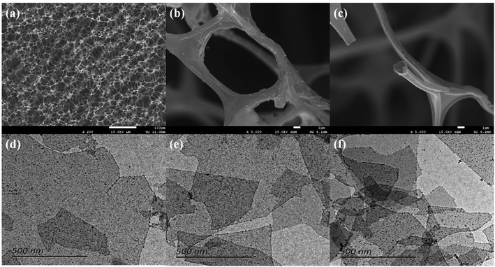 | ||
| Fig. 4 Typical microstructure SEM images of carbon foam (a–c); TEM images of Ti3C2TX suspension with 0.2 mg ml−1 (d), 1 mg ml−1 (e), 3 mg ml−1 (f). | ||
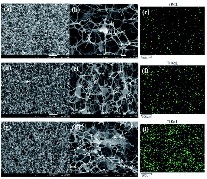
Fig. 5(a, d and g) show the cross-sectional microstructure of CF/MXene-N1, CF/MXene-N2 and CF/MXene-N3. It can be seen that the CF/MXene samples still maintain the 3D skeleton structure with high porosity (about 99.4%) and the ultralow densities of only 5–7 mg cm−3. The magnified images in Fig. 5(b, d and f) show the distribution of Ti3C2TX nanosheets in the CF. For CF/MXene-N1, Ti3C2TX nanosheets are sparse in CF as shown in Fig. 5(b), but for CF/MXene-N2 and CF/MXene-N3, the content of Ti3C2TX nanosheets are gradually increasing (Fig. 5(e and h)). A large amount of flake-like Ti3C2TX MXene is present inside the CF, which is not only attached to the surface of the carbon skeleton but also filled in the cells of the CF. EDS map analysis Ti element was used to determine the distribution of Ti3C2TX nanosheets in the samples. The distribution of Ti element in the foam skeleton in Fig. 5(c) is very rare and uniform, indicating that the content of Ti3C2TX nanosheets in CF/MXene-N1 is sparse but uniform. As can be seen from Fig. 5(f and i), the distribution of Ti element becomes denser, indicating that the content of Ti3C2TX nanosheets is gradually higher. More important, the distributions of Ti3C2TX nanosheets in CF/MXene-N2 and CF/MXene-N3 are still fairly uniform.
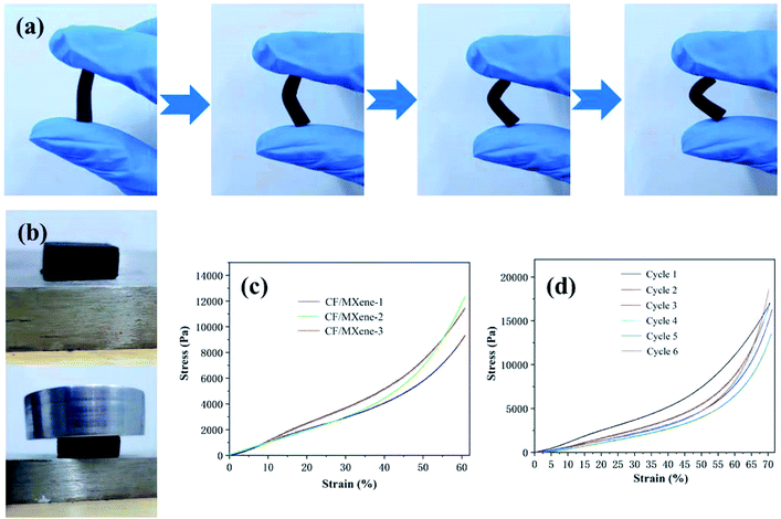
In Fig. 6(a), a CF/MXene specimen is bent over 90° and still has no fracture, showing excellent flexibility. This is mainly because the CF/MXene still retains the 3D structure and the high aspect ratio of the CF, which shown in Fig. 5(b, e and h). Moreover, the CF/MXene specimen can also be compressed without cracking as shown in Fig. 6(b). Fig. 6(c) shows typical elastic compressive stress–strain curves of CF/MXene-1, CF/MXene-2 and CF/MXene-3. It can be seen that even if the strain of the three samples exceeds 60%, there is no break. During the experiment, the CF/MXene-3 sample was compressed by 70% and then unloaded. After the sample was restored to its original shape, it was continuously pressed 6 times with the same strain cycle, and the stress–strain curve was measured each time as shown in Fig. 6(d). It can be seen that the stress of the sample did not decrease significantly, indicating the CF/MXene sample has excellent resilience and flexibility.
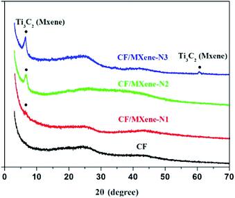
Fig. 7 shows the XRD patterns of CF, CF/MXene-N1, CF/MXene-N2 and CF/MXene-N3. It can be seen that CF has no obvious diffraction peak, indicating the CF is a kind of amorphous carbon.32 In addition, CF/MXene-N1, CF/MXene-N2 and CF/MXene-N3 samples show the characteristic peaks at 7.17° corresponding to the f-Ti3C2TX peak of (002) plane.33 However, as the content of Ti3C2TX nanosheets in CF/MXene decreased, the diffraction peaks intensity of Ti3C2TX gradually decreased.
Fig. 8 shows the N2 adsorption–desorption isotherms of CF, CF/MXene-N1, CF/MXene-N2 and CF/MXene-N3 samples that have changed greatly with the different content of Ti3C2TX nanosheets. Calculation suggests that the SSA value of CF is 8.1376 m2 g−1. However, after adsorbing Ti3C2TX nanosheets, the values of CF/MXene-N1, CF/MXene-N2 and CF/MXene-N3 specific surface area are significantly increased, reaching up to 35.6227 m2 g−1, 51.6036 m2 g−1 and 72.4327 m2 g−1, respectively, which are 4–9 times more than that of pure CF. The increased SSA due to the abundant interfaces and defects is beneficial to EM dissipation.34 Therefore, the introduction of Ti3C2TX nanosheets into CF is benefit to improve the absorption efficiency of EM waves.
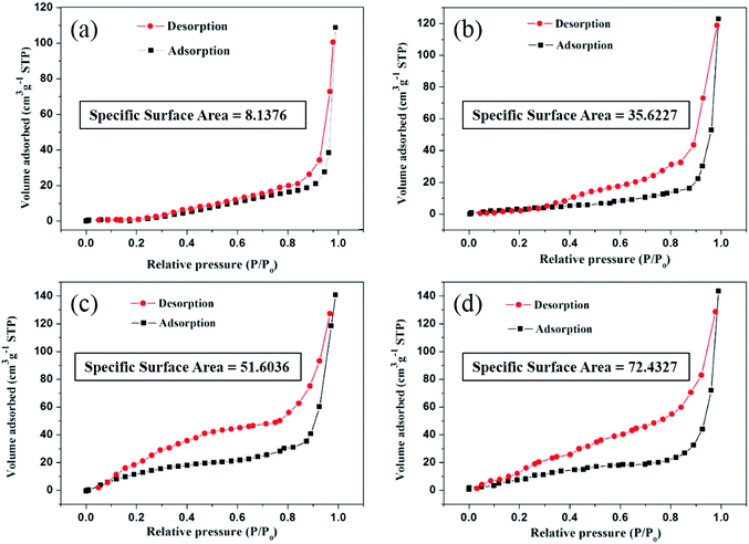 | ||
| Fig. 8 N2 adsorption–desorption isotherms of CF (a), CF/MXene-N1 (b), CF/MXene-N2 (c) and CF/MXene-N3 (d). | ||
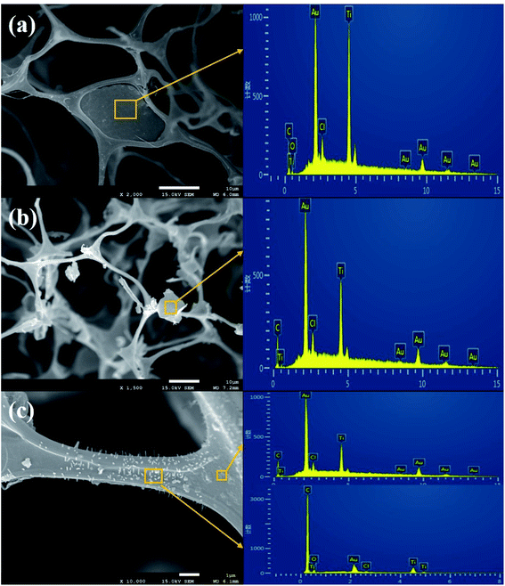
Fig. 9 shows three typical states of Ti3C2TX nanosheets in CF/MXene samples. In Fig. 9(a), a film formed by agglomeration of Ti3C2TX nanosheets covers the whole micropores of CF. Meanwhile, the O and Cl elements peaks are detected in the result of EDS analysis, indicating the Cl− and O2− functional groups are present in the prepared Ti3C2TX MXene. In addition, the existence of the Au element is due to the gold sputtering process. As shown in Fig. 9(b), some small sized Ti3C2TX nanosheet aggregates verified by EDS hang on the CF skeleton. In Fig. 9(c), a large number of Ti3C2TX nanosheets arranged in a vertical array or in a flat arrangement closely attach to the CF skeleton. The three states of Ti3C2TX nanosheets in the hybrids are formed during the freeze-drying process, which are affected by the Ti3C2TX suspension concentration and the freezing rate. It should be noted that the Ti3C2TX nanosheets or aggregates are isolated from each other, which makes it possible to generate local electric fields and polarization, thereby facilitating the absorption of EM waves.
The relative complex permittivity of CF/MXene and CF samples, including the real part ε′, imaginary part ε′′, and tangent loss tan δ = ε′′/ε′, was investigated in the coverage frequency ranging from 2 to 18 GHz, as shown in Fig. 10. The ε′ represents the ability to store electromagnetic waves, while the ε′′ represents the ability to consume electromagnetic waves. As illustrated in Fig. 10(a and b), the ε′ and ε′′ values show a downward trend at the same time with the increase of the frequency obviously. In Fig. 10(a), the ε′ are increasing with the increase of the Ti3C2TX nanosheet contents, while for the ε′′, the values increase first, and then decrease as shown in Fig. 9(b). In addition, there is a significant difference between CF and the CF/MXene samples, the ε′′ and ε′′ values of CF sample are lowest, indicating that its EM absorbing performance is weaker than others. Based on the Debye theory, ε′ and ε′′ were calculated by the following equations:14,35
| ε′ = ε∞ + (εs − ε∞)/(1 + ω2τ2) | (1) |
| ε′′ = (εs − ε∞)ωτ/(1 + ω2τ2) + σac/ωε0 | (2) |
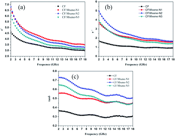 | ||
Fig. 10 Frequency dependence of (a) the real part ε′ and (b) imaginary part ε′′, (c) tangent loss (tan![[thin space (1/6-em)]](https://www.rsc.org/images/entities/char_2009.gif) δ). δ). | ||
What is more, Fig. 10(c) also shows the variation tendency of tan![[thin space (1/6-em)]](https://www.rsc.org/images/entities/char_2009.gif) δ values, which represent the EM dissipation capability of different samples.28,36 It can be seen the EM dissipation capability enhanced significantly with the addition of Ti3C2TX nanosheets, but if the content of Ti3C2TX nanosheets is too high, the tan
δ values, which represent the EM dissipation capability of different samples.28,36 It can be seen the EM dissipation capability enhanced significantly with the addition of Ti3C2TX nanosheets, but if the content of Ti3C2TX nanosheets is too high, the tan![[thin space (1/6-em)]](https://www.rsc.org/images/entities/char_2009.gif) δ values will decrease again, as shown in the curve of CF/MXene-N3. In fact, EM absorption performance not only relates to the dissipation of EM waves, but also closely depends on the impedance matching, which determines the ability of incident EM to enter the absorber.37,38 Zin values represent the input impedance at the interface between the air and the absorber based on the transmission line theory in eqn (3).39,40
δ values will decrease again, as shown in the curve of CF/MXene-N3. In fact, EM absorption performance not only relates to the dissipation of EM waves, but also closely depends on the impedance matching, which determines the ability of incident EM to enter the absorber.37,38 Zin values represent the input impedance at the interface between the air and the absorber based on the transmission line theory in eqn (3).39,40
Zin = (μ/ε)1/2![[thin space (1/6-em)]](https://www.rsc.org/images/entities/char_2009.gif) tanh[j(2πfd/c)(με)1/2] tanh[j(2πfd/c)(με)1/2]
| (3) |
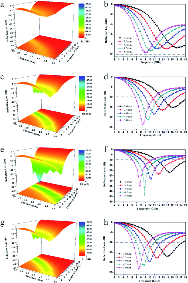
Reflection loss values (RL) of CF, CF/MXene-N1, CF/MXene-N2 and CF/MXene-N3 represent the EM absorption performance of samples, which has been demonstrated in Fig. 11. In general, a material with an RL value of <−10 dB is considered to be an effective EM absorber, which means that >90% incident EM is absorbed and the corresponding frequency range is called the effective absorption bandwidth (EAB).
Fig. 11(a and b) shows the 3D representations and curves variation of RL values with thickness (0–5 mm) and frequency (2–18 GHz) of CF. Clearly, the RL values of the CF don't reach −10 dB in the whole frequency range at any thickness, which indicate the EM absorption performance of CF is poor. Remarkably, with the addition of Ti3C2TX nanosheets, the EM absorption performance of CF/MXene-N1 is significantly improved, as illustrated in Fig. 10(c and d). When the matching thickness is 5 mm, the minimum RL (RLmin) goes up to −24.6 dB at 8 GHz with the effective absorption bandwidth (EAB) of 4.5 GHz from 6.7 GHz to 11.2 GHz. It can also be seen from Fig. 11(d) that the RLmin transfers to a lower frequency with increasing matching thickness according with the law of quarter-wavelength attenuation.41–43 More importantly, the EAB is always wide enough, when the thicknesses distribute between 3 and 5 mm. For the CF/MXene-N2, as shown in Fig. 10(e and f), the RLmin is further reduced to −45 dB at 8.8 GHz with the thickness of 4.5 mm, demonstrating superior EM absorbing performance. What is more, the EAB can also reach up to 5 GHz (6.9–11.9 GHz). This is because more Ti3C2TX nanosheets adsorbing on the CF skeleton further increase the specific surface area, resulting in more defects and interfaces, which is more conducive to the dissipation of EM waves. However, for CF/MXene-N3 as shown in Fig. 11(g and h), the RLmin values increase to −24.1 dB at the thickness of 5 mm, indicating the further increase of Ti3C2TX nanosheets is not conducive to the absorption of EM waves. The decrease of absorbing performance of CF/MXene-N3 can be attributed to the bad impedance matching, which is caused by the high conductivity of excess Ti3C2TX nanosheets.
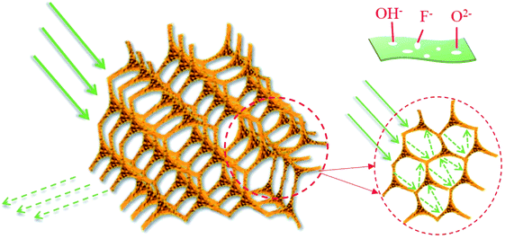
Fig. 12 presents the associated EM absorption mechanism of carbon foam/Ti3C2TX hybrids. 3D CF provides a large number of micropores, not only reduces the density but also effectively prevent the agglomeration of Ti3C2TX nanosheets. First, the Ti3C2TX nanosheets deposited on the surface of CF skeleton can provide more surface area and interface structure. At the same time, the 3D structure greatly increases the propagation path of EM waves, causing the incident EM waves to be attenuated through zigzag reflection and scattering.44,45 Second, the residual OH−, F− and O2− functional groups and localized defects in Ti3C2TX nanosheets act as polarized centers.46,47 Third, there is a large amount of electron migration at the defects and interfaces between Ti3C2TX nanosheets and CF skeleton in the alternated EM environment, thereby forming a rich field-induced microcurrent.28 Furthermore, the microcurrents improves the conductivity and enhance the conductive loss. However, the increased conductivity with the increasing content of Ti3C2TX nanosheets will inevitably lead to a bad impedance matching, resulting in a decline in the overall EM absorption performance. This can explain the reason of the EM absorption performance degradation for CF/MXene-N3.
Table 1 summarizes and compares the representative foam-based EM absorption materials reported in recent years. It can be seen the RGO foam has ultra-low density, but the thickness is high reached to 10 mm. The C/Fe foam and RGO/CNT foam have excellent absorption intensity, but their density is relatively high, and the EAB is narrow. Notably, the CF/MXene-N2 in this work possesses better EM absorption performance than most current foam-based EM absorbers, which has strong absorption intensity (RLmin = −45.0 dB), broad EAB (5.0 GHz), ultra-low density (only 0.006 g cm−3) and low thickness (4.5 mm), indicating the carbon foam/Ti3C2TX hybrids have a huge potential as an excellent EM absorption materials.
| Sample | Matrix | Density (g cm−3) | RL ≤ −10 dB | RLmin (dB) | Ref. | |
|---|---|---|---|---|---|---|
| d (mm) | EAB (GHz) | |||||
| RGO foam | Wax | 0.9 | 10 | 4.2 | −27.0 | 3 |
| RGO/PPy/Fe3O4 | Wax | 0.900 | 3 | 4.2 | −49.2 | 11 |
| SiC/CF-aerogel | Wax | 0.112 | 3.5 | 1.6 | −18.4 | 14 |
| RGO/SiCnws foam | PDMS | 0.097 | 3.00 | 4.2 | −19.6 | 19 |
| C foam | Epoxy | 1.600 | 1.2 | 2.0 | −10.0 | 20 |
| C/Fe foam | Air | 0.130 | 10.4 | 0.2 | −45.0 | 21 |
| Ti3C2TX/SiCnws foams | None | 0.029 | 3.5–3.8 | 4.2 | −55.7 | 28 |
| Fe3O4/TiO2/EP | Epoxy | 1.600 | 1.2 | 4.2 | −22.0 | 36 |
| C/SiCnws foam | Epoxy | 1.600 | 3.30 | 4.2 | −31.0 | 48 |
| RGO/CNT foam | PDMS | 0.097 | 2.75 | 3.5 | −55.0 | 49 |
| RGO/ZnOnws foam | PDMS | 0.097 | 4.8 | 4.2 | −27.8 | 50 |
| CF/MXene-N2 | Wax | 0.006 | 4.5 | 5 | −45.0 | This work |
Conclusions
In summary, a new flexible and ultralight carbon foam/Ti3C2TX MXene hybrid was prepared by vacuum impregnation and freeze-drying process. The Ti3C2TX nanosheets are uniformly dispersed inside the 3D CF, which significantly increases the specific surface area of the hybrid. Also, the hybrid has excellent resilience and flexibility, even if the strain exceeds 70% after 6 cycles. This is mainly because the CF/MXene hybrid retains the 3D structure and the high aspect ratio of the carbon skeleton. For the CF/MXene-N2, when the content of Ti3C2TX nanosheets is 9.8%, the RLmin is significantly reduced to −45 dB at 8.8 GHz with the thickness of 4.5 mm, and the EAB can also reach up to 5 GHz, indicating the new carbon foam/Ti3C2TX hybrid has huge potential to be used as new high performance EM absorption materials.Conflicts of interest
The authors declare no conflict of interest.Acknowledgements
This work was supported by the priority Academic Program Development of Jiangsu Higher Education Institutions (PAPD), Qing Lan Project of Jiangsu Province, the Program for Chang jiang Scholars and Innovative Research Team in University (PCSIRT), IRT1146 and IRT15R35, and the Top–notch Academic Programs Project of Jiangsu Higher Education Institutions (TAPP, PPZY2015B128).References
- X. Liang, W. Liu, Y. Cheng, J. Lv, S. Dai, D. Tang, B. Zhang and G. Ji, J. Alloys Compd., 2018, 749, 887–899 CrossRef CAS.
- B. Dai, B. Zhao, X. Xie, T. Su, B. Fan, R. Zhang and R. Yang, J. Mater. Chem. C, 2018, 6, 5690–5697 RSC.
- Y. Zhang, Y. Huang, H. Chen, Z. Huang, Y. Yang, P. Xiao, Y. Zhou and Y. Chen, Carbon, 2016, 105, 438–447 CrossRef CAS.
- W. Duan, X. Yin, Q. Li, L. Schlier, P. Greil and N. Travitzky, J. Eur. Ceram. Soc., 2016, 36, 3681–3689 CrossRef CAS.
- K. Zhang, H. O. Yu, Y. D. Shi, Y. F. Chen, J. B. Zeng, J. Guo, B. Wang, Z. Guo and M. Wang, J. Mater. Chem. C, 2017, 5, 2807–2817 RSC.
- Y. Z. Wei, G. S. Wang, Y. Wu, Y. H. Yue, J. T. Wu, C. Lu and L. Guo, J. Mater. Chem. A, 2014, 2, 5516–5524 RSC.
- X. Yin, L. Kong, L. Zhang, L. Cheng, N. Travitzky and P. Greil, Int. Mater. Rev., 2014, 59, 326–355 CrossRef CAS.
- W. Liu, H. Li, Q. Zeng, H. Duan, Y. Guo, X. Liu, C. Sun and H. Liu, J. Mater. Chem. A, 2015, 3, 3739–3747 RSC.
- J. Zhu, S. Wei, N. Haldolaarachchige, D. P. Young and Z. Guo, J. Phys. Chem. C, 2011, 115, 15304–15310 CrossRef CAS.
- P. Xie, H. Li, B. He, F. Dang, J. Lin, R. Fan, C. Hou, H. Liu, J. Zhang, Y. Ma and Z. Guo, J. Mater. Chem. C, 2018, 6, 8812–8822 RSC.
- C. Zhang, Y. Chen, H. Li, R. Tian and H. Liu, ACS Omega, 2018, 3, 5735–5743 CrossRef CAS PubMed.
- C. Zhang, H. Li, Z. Zhuo, R. Dugnani, C. Sun, Y. Chen and H. Liu, RSC Adv., 2017, 7, 41321–41329 RSC.
- S. Dong, J. Song, X. Zhang, P. Hu, B. Sun, S. Zhou and X. Luo, J. Mater. Chem. C, 2017, 5, 11837–11846 RSC.
- X. Ye, Z. Chen, S. Ai, B. Hou, J. Zhang, X. Liang, Q. Zhou, H. Liu and S. Cui, ACS Sustainable Chem. Eng., 2019, 7, 2774–2783 CrossRef CAS.
- X. Sun, J. He, G. Li, J. Tang, T. Wang, Y. Guo and H. Xue, J. Mater. Chem. C, 2013, 4, 765–777 RSC.
- Y. Lu, Y. Wang, H. Li, Y. Lin, Z. Jiang, Z. Xie, Q. Kuang and L. Zheng, ACS Appl. Mater. Interfaces, 2015, 7, 13604–13611 CrossRef CAS PubMed.
- C. Wang, Y. Ding, Y. Yuan, X. He, S. Wu, S. Hu, M. Zou, W. Zhao, L. Yang, A. Cao and Y. Li, J. Mater. Chem. C, 2015, 3, 11893–11901 RSC.
- F. Moglie, D. Micheli, S. Laurenzi, M. Marchetti and V. M. Primiani, Carbon, 2012, 50, 1972–1980 CrossRef CAS.
- M. Han, X. Yin, Z. Hou, C. Song, X. Li, L. Zhang and L. Cheng, ACS Appl. Mater. Interfaces, 2017, 9, 11803–11810 CrossRef CAS PubMed.
- J. Yang, Z. M. Shen and Z. B. Hao, Carbon, 2004, 6, 1882–1885 CrossRef.
- S. Wang, N. Xiao, Y. Zhou, Z. Ling, M. Li and J. Qiu, Carbon, 2016, 105, 224–226 CrossRef.
- H. B. Zhao, Z. B. Fu, H. B. Chen, M. L. Zhong and C. Y. Wang, ACS Appl. Mater. Interfaces, 2016, 8, 1468–1477 CrossRef CAS PubMed.
- M. Naguib, V. N. Mochalin, M. W. Barsoum and Y. Gogotsi, Adv. Mater., 2014, 26, 992–1005 CrossRef CAS PubMed.
- M. Han, X. Yin, H. Wu, Z. Hou, C. Song, X. Li, L. Zhang and L. Cheng, ACS Appl. Mater. Interfaces, 2016, 8, 21011–21019 CrossRef CAS PubMed.
- X. Li, X. Yin, M. Han, C. Song, X. Sun, H. Xu, L. Cheng and L. Zhang, J. Mater. Chem. C, 2017, 5, 7621–7628 RSC.
- Y. Qing, W. Zhou, F. Luo and D. Zhu, Ceram. Interfaces, 2016, 42, 16412–16416 CrossRef CAS.
- M. Han, X. Yin, X. Li, B. Anasori, L. Zhang, L. Cheng and Y. Gogotsi, ACS Appl. Mater. Interfaces, 2017, 9, 20038–20045 CrossRef CAS PubMed.
- X. Li, X. Yin, H. Xu, M. Han, M. Li, S. Liang, L. Cheng and L. Zhang, ACS Appl. Mater. Interfaces, 2018, 10, 34524–34533 CrossRef CAS PubMed.
- Y. Qian, H. Wei, J. Dong, Y. Du, X. Fang, W. Zheng, Y. Sun and Z. Jiang, Ceram. Int., 2017, 43, 10757–10762 CrossRef CAS.
- Y. Tong, M. He, Y. Zhou, X. Zhong, L. Fan, T. Huang, Q. Liao and Y. Wang, Appl. Surf. Sci., 2018, 434, 283–293 CrossRef CAS.
- C. J. Zhang, S. Pinilla, N. McEvoy, C. P. Cullen, B. Anasori, E. Long, S. Park, A. Seral-Ascaso, A. Shmeliov, D. Krishnan, C. Morant, X. Liu, G. Duesberg, Y. Gogotsi and V. Nicolosi, Chem. Mater., 2017, 29, 4848–4856 CrossRef CAS.
- Z. Fang, C. Li, J. Sun, H. Zhang and J. Zhang, Carbon, 2007, 45, 2873–2879 CrossRef CAS.
- O. Mashtalir, M. Naguib and V. N. Mochalin, Nat. Commun., 2013, 4, 1716 CrossRef PubMed.
- H. Xu, X. Yin, M. Zhu, M. Han, Z. Hou, X. Li, L. Zhang and L. Cheng, ACS Appl. Mater. Interfaces, 2017, 9, 6332–6341 CrossRef CAS PubMed.
- X. Liang, B. Quan, J. Chen, D. Tang, B. Zhang and G. Ji, Sci. Rep., 2017, 7, 9462 CrossRef PubMed.
- J. Liu, R. Che, H. Chen, F. Zhang, F. Xia, Q. Wu and M. Wang, Small, 2012, 8, 1214–1221 CrossRef CAS PubMed.
- F. X. Qin, C. Brosseau and H. X. Peng, Chem. Phys. Lett., 2013, 579, 40–44 CrossRef CAS.
- L. Quan, F. X. Qin, D. Estevez, H. Wang and H. X. Peng, Carbon, 2017, 125, 630–639 CrossRef CAS.
- C. Zhou, X. Wang, H. Luo, L. Deng, S. Wei, Y. Zheng, Q. Jia and J. Liu, Chem. Eng. J., 2019, 123095, DOI:10.1016/j.cej.2019.123095.
- C. Zhou, X. Wang, H. Luo, L. Deng, S. Wang, S. Wei, Y. Zheng, Q. Jia and J. Liu, Appl. Surf. Sci., 2019, 494, 540–550 CrossRef CAS.
- B. Zhao, G. Shao, B. Fan, W. Zhao and R. Zhang, J. Mater. Chem. C, 2015, 3, 10862–10869 RSC.
- B. Zhao, B. Fan, Y. Xu, G. Shao, X. Wang, W. Zhao and R. Zhang, ACS Appl. Mater. Interfaces, 2015, 7, 26217–26225 CrossRef CAS PubMed.
- W. She, H. Bi, Z. Wen, Q. Liu, X. Zhao, J. Zhang and R. Che, ACS Appl. Mater. Interfaces, 2016, 8, 9782–9789 CrossRef CAS PubMed.
- B. Zhao, X. Guo, W. Zhao, J. Deng, G. Shao, B. Fan, Z. Bai and R. Zhang, ACS Appl. Mater. Interfaces, 2016, 8, 28917–28925 CrossRef CAS PubMed.
- B. Zhao, J. Deng, C. Zhao, C. Wang, Y. Chen, M. Hamidinejad, R. Li and C. Park, J. Mater. Chem. C, 2019 10.1039/C9TC04575A.
- C. Mo, L. Zhang and G. Wang, Nanostruct. Mater., 1995, 6, 823–826 CrossRef.
- H. Xu, X. Yin, M. Zhu, M. Han, Z. Hou and X. Li, ACS Appl. Mater. Interfaces, 2017, 9, 6332–6341 CrossRef CAS PubMed.
- S. Xiao, H. Mei, D. Han, K. G. Dassios and L. Cheng, Carbon, 2017, 122, 718–725 CrossRef CAS.
- C. Song, X. Yin, M. Han, X. Li, Z. Hou, L. Zhang and L. Cheng, Carbon, 2017, 116, 50–58 CrossRef CAS.
- L. Kong, X. Yin, X. Yuan, Y. Zhang, X. Liu, L. Cheng and L. Zhang, Carbon, 2014, 73, 185–193 CrossRef CAS.
| This journal is © The Royal Society of Chemistry 2019 |

