 Open Access Article
Broadband microwave absorber constructed by reduced graphene oxide/La0.7Sr0.3MnO3 composites†
Kelan Yana,
Feng Yina,
Chao Panga,
Xiuhui Zuoa,
Qitu Zhangb,
Liming Shena,
Runhua Fanc and
Ningzhong Bao *a
*a
aState Key Laboratory of Material-Oriented Chemical Engineering, College of Chemical Engineering, Nanjing Tech University, Nanjing, Jiangsu 210009, P. R. China. E-mail: nzhbao@njtech.edu.cn; Fax: +86 25 83172244; Tel: +86 25 83172244
bCollege of Materials Science and Engineering, Nanjing Tech University, Nanjing, Jiangsu 210009, P. R. China
cCollege of Ocean Science and Engineering, Shanghai Maritime University, Shanghai 201306, China
First published on 17th December 2019
Abstract
High-performance microwave absorbing materials require optimized impedance matching and high attenuation ability. Here we meet the challenge by incorporating electric loss with magnetic loss materials to prepare carbon-based/magnetic hybrids. The reduced graphene oxide (rGO)/La0.7Sr0.3MnO3 (LSMO) composites were prepared by dispersing the LSMO powders into 4.25, 6.25, 8.16, and 10 wt% of the graphene oxide aqueous solution, then the rGO/LSMO composites were formed by hydrothermal method. The pure rGO, LSMO, and rGO/LSMO composites were studied using X-ray diffraction and SEM. Microwave absorption properties were investigated by using coin method. Simulation studies show that 6.25 wt% of rGO/LSMO in a wax matrix exhibits the strongest reflection loss of −47.9 dB @ 10.7 GHz at a thickness of 2.5 mm. Moreover, the effective absorption bandwidth with the reflection loss below −10 dB is up to 14.5 GHz, ranged from 3.5 to 18 GHz for the composites with a thickness of 1.5–5.5 mm, due to a synergism between dielectric loss of rGO and magnetic loss of magnetic LSMO, which is an interesting exploration in the applications of rGO and LSMO. This method can be extended to design and fabricate hybrid absorbers with effective microwave absorption.
Introduction
Microwave absorbing materials have attracted broad interest because of their prospective applications in the electronics industry, information technology, and military affairs.1–3 During the past decades, considerable efforts have been made to develop high-performance microwave absorbing materials with low density, tiny thickness, strong wave absorption, and broad bandwidth, especially in the gigahertz (GHz) band range.4 Magnetic metals or alloys, magnetic oxides, and their composites have been widely used as fillers to fabricate microwave absorbing materials.5 However, their drawbacks, such as high density, poor chemical and thermal stability, and large loading content, have severely hindered their practical applications. Carbon-based materials as electric loss fillers with lightweight and efficient absorption have been extensively studied, especially for the carbon nanotubes with a low specific gravity, high aspect ratios, and excellent electrical conductivities and ultra-low loadings.6 However, the microwave absorbing ability of CNTs is relatively weak. For instance, both the CNT@TiO2 and CNT@SiO2 exhibit minimum reflection loss value of −31.8 dB @ 10.35 GHz and −10.22 dB @ 9.90 GHz with the thickness of 2 mm and 5 mm.7,8As the thinnest material of the carbon family, graphene has shown great potential for microwave absorption materials,9 due to its unique two-dimensional structure and desirable properties such as low density, high thermal and chemical stability, and high carrier mobility.10,11 However, the microwave attenuation by pure graphene is difficult due to poor impedance matching from the single dielectric loss. Excellent microwave absorption generally requires efficient synergism between the relative permittivity and permeability. One of the effective ways is the combination of a magnetic material with graphene.12,13 Additionally, the permeability is very low due to the weak magnetic characteristic in the microwave band, the permittivity must be low for good impedance matching, so abundant defects and hydroxyl, epoxy, and carboxyl groups of reduced graphene oxide (rGO) result in low permittivity, which is beneficial for the microwave absorption.14
La0.7Sr0.3MnO3 (LSMO) is a kind of important magnetic material with the metallicity and ferromagnetism.15 Thus, LSMO has wide applications in various fields such as gas sensors, optoelectronic and spintronics, etc.16–21 Compared to the magnetic metals and ferrites, LSMO exhibits remarkably improved microwave absorption properties, due to the metallicity, chemical and thermal stability. However, pure magnetic LSMO as a microwave absorber exhibits very weak absorption ability due to its impedance mis-matching.22 The carriers of LSMO can travel within the majority band, derived from Mn 3d eg and O 2p orbitals when neighboring Mn core spins are aligned, but in a general environment, it is difficult for LSMO to facilitate charge transport due to the spin channel gap. Until now, there have been no useful ways to improve the charge transport, and thus previous researchers found that incorporation of dielectric-loss materials of graphene with high carrier mobility into LSMO is an effective strategy to enhanced microwave absorption abilities.23,24
To further investigate the wave absorption property of LSMO, we prepared LMSO by a simple sol–gel method and combined them with rGO using hydrothermal process to form rGO/LMSO composites. As a result, 6.25 wt% of rGO/LSMO in wax matrix exhibits the strongest reflection loss of −47.9 dB @ 10.7 GHz at a thickness of 2.5 mm. Moreover, the effective absorption bandwidth with the reflection loss below −10 dB is up to 14.5 GHz, ranged from 3.5 to 18 GHz for the composites with the thickness in 1.5–5.5 mm, due to a synergism between dielectric loss of rGO and magnetic loss of magnetic LSMO, which is an interesting exploration in the physical application of rGO and LSMO. It is meaningful for the design and fabrication of hybrid absorbers with effective microwave absorption.
Experimental
Materials
Crystalline flake graphite (100 mesh) was purchased from Qingdao Meizhen Company (China). Potassium permanganate (KMnO4) reagent (99%), H2SO4 (98%), HNO3 (70%) and strontium acetate Sr(OAc)2 (99.0%) were purchased from Sigma-Aldrich. Lanthanum nitrate La(NO3)3 (99.0%), anhydrous ethanol (99.7%), glacial acetic acid (99.5%), ethanolamine (99.5%), and manganese acetate Mn(OAc)2 (99.0%) were supplied by Sinopharm Chemical Reagent Co. (China).Synthesis of La0.7Sr0.3MnO3 (LSMO)
The La0.7Sr0.3MnO3 (LSMO) powders were prepared by the sol–gel method. In a typical experiment, lanthanum nitrate La(NO3)3 (99.0%) was first dissolved in anhydrous ethanol (99.7%), strontium acetate Sr(OAc)2 (99.0%) and manganese acetate Mn(OAc)2 (99.0%) were fully dissolved in glacial acetic acid (99.5%), and then the above two solutions were mixed together, the mixed solution was stabilized by adding ethanolamine (99.5%) as a chelating agent, and then stirred to become transparent sol. The sol was dried at 80 °C in an oven, and then calcinated at 1100 °C to get polycrystalline oxide powders with a particle size of ∼100 nm, shown in Fig. 2 and S1(a).†Synthesis of graphene oxide (GO)
The graphene oxide (GO) was prepared by oxidation of natural graphite powders using a modified Hummers' method, according the reported procedure.25–27Synthesis of reduced graphene oxide/LSMO composites
The rGO/LSMO composites were prepared by hydrothermal method. As shown in Fig. 1, the details of the experimental procedure are as follows: the GO aqueous solution (4, 6, 8, and 10 mg mL−1) mixed with La0.7Sr0.3MnO3 powder was hydrothermally treated in a custom Teflon-lined autoclave (φ160 × 25 mm) at 180 °C for 3 hours, a water-filled intermediate rGO/LSMO solid composites (as shown in Fig. S1b†) were formed by in situ self-assembling, and the water-filled composites with initial 4.25, 6.25, 8.16, and 10 wt% of GO were freeze-dried to remove the remaining water inside, and the samples were marked as 4.25 wt% rGO/LSMO, 6.25 wt% rGO/LSMO, 8.16 wt% rGO/LSMO, and 10 wt% rGO/LSMO, respectively.Characterizations
The crystalline phase of samples was examined with X-ray diffraction (XRD) by using a D8-Advance, Bruker AXS diffractometer (Cu-Kα radiation, λ = 1.5418 Å) in the continuous scan mode over 10–45° (2θ) with a scan rate of 0.3° s−1, operating at 40 kV and 40 mA. The morphology and microstructure of samples were characterized by field-emission scanning electron microscopy (FESEM, HITACHI S-4800).Based on the transmission/reflection method, the relative complex permittivity (ε′ and ε′′), permeability (μ′ and μ′′), and the electromagnetic absorption performance (reflection loss RL) were evaluated in the range 2–18 GHz using an Agilent HP8722E vector network analyzer. A 30 wt% of paraffin was used as the supporting matrix due to its minor complex electromagnetic parameters approximating those of air. The toroidal test sample (3 mm i.d., 7 mm o.d., and 2 mm thickness) was fabricated. The incident microwave direction was perpendicular to the test samples.
Results and discussion
The synthesis of the rGO/LSMO composites is illustrated in Fig. 1. To reveal the morphology and microstructure of the obtained samples, SEM analyses were carried out. Fig. 2 show a typical SEM images of rGO/LSMO composites with different weight percentages of rGO (4.25, 6.25, 8.16, and 10.0 wt%). It can be found that the LSMO particles distribute in flaky structure of rGO, and attach closely on the surface of a lamellar structure of alternating plates as shown in Fig. 2(a–d). Moreover, the two-dimensional rGO sheets with a large specific surface area formed a conductive network in the composites with the increasing of rGO content, clearly shown in Fig. 2(c and d).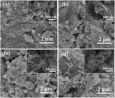 | ||
| Fig. 2 SEM images of rGO/LSMO composites with different weight percentages of rGO; (a) 4.25 wt%, (b) 6.25 wt%, (c) 8.16 wt%, and (d) 10.0 wt%. | ||
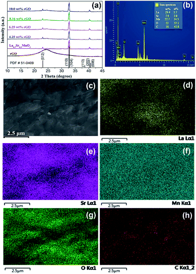
As shown in Fig. 3(a), the major diffraction peaks at 23.10°, 32.70°, 32.91°, 38.61°, 40.34°, and 40.68° marked by Miller indices of (012), (110), (104), (113), (202), and (006) respectively, can be indexed to lanthanum strontium manganese oxide (La0.7Sr0.3MnO3, PDF#51-0409); and weak diffraction peaks of rGO suggesting that LSMO in the composites are well-crystallized, without detectable secondary phase within the sensitivity limits of the experiment. The chemical components of 6.25 wt% rGO/LSMO composite are analyzed by energy-dispersive X-ray spectroscopy (EDS). From the EDS images (Fig. 3(b–h)), it can be found that the La, Sr, Mn, O, and C elements are all homogenously distributed, and the molar ratio of La/Sr is around 2.
Here we firstly investigate the microwave absorption properties of rGO/LSMO composites with different weight percentages of rGO (4.25, 6.25, 8.16, and 10.0 wt%). Fig. 4(a) shows the real part ε′ and imaginary part ε′′ of the relative complex permittivity (ε) for rGO/LSMO composites in the frequency range of 2–18 GHz. The ε′ values are decreasing as the frequency increasing in the range of 7.1–14.1 over 2–18 GHz, and the ε′′ values decrease from 6.8 to 3.4, exhibiting obvious frequency-dependent dielectric response. This may arise from the lag of the induced charges to follow the reversing external field at high frequencies, and finally causes a reduction in the electronic oscillations, indicating a typical form of conduction dominance, which is similar to the results of 2D carbide MXene films.28,29 The ε′ values of rGO/LSMO composites are significantly smaller than that of rGO (40–80) and LSMO (25–32), as shown in Fig. S2(a) and S3.† Conventionally, the permittivity can generally be represented by the Debye dipolar relaxation expression of Cole–Cole semicircle. The ε′ and ε′′ of permittivity are shown as follows,30
 | (1) |
 | (2) |
| (ε′ − ε∞)2 + (ε′′)2 = (εs − ε∞)2 | (3) |
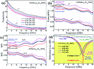 | ||
| Fig. 4 The permittivity, permeability, dielectric loss (tgδε), magnetic loss (tgδμ), and reflection loss (RL) of rGO, LSMO and rGO/LSMO with different weigh percentages of rGO. | ||
The curve characteristics of ε′ versus ε′′ for rGO/LSMO composites are shown in Fig. 5, in which the presence of clear segment of semicircle and a tail suggesting the existence of dielectric relaxation processes and the influence of leakage conductance, while the semicircle is representative of a Debye dipolar relaxation and the tail is related to the conductance effect derived from the rGO.
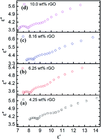 | ||
| Fig. 5 The Cole–Cole plots of rGO/LSMO composites with different rGO content; (a) 4.25 wt%, (b) 6.25 wt%, (c) 8.16 wt%, (d) 10.0 wt%. | ||
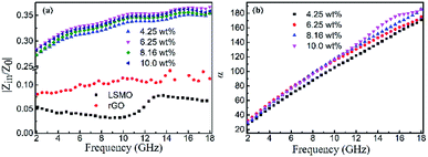
Fig. 4(b) shows the real part μ′ and imaginary part μ′′ of the relative complex permeability (μr) for rGO/LSMO composites in the frequency range of 2–18 GHz. The μ′ values are in the range of 0.96–1.1 over 2–18 GHz, while the μ′′ values decrease from 0.06 to −0.08. It is interesting that the μ′ values of rGO/LSMO composites are significantly higher than that of rGO (∼0.6) and LSMO (0.1–0.2), as shown in Fig. S2(b) and S3.† Interestingly, within the frequency range of 7.4–18 GHz, the microwave permeability with negative imaginary parts (μ′′) has also been observed. The phenomenon of the negative μ′′ within the high frequency microwave range have been observed in many composite systems, such as hierarchical Ni nanostrucutres, multiwalled carbon nanotube composites, porous Fe3O4/SnO2 core/shell nanorods, hollow cobalt nanochains, mesoporous carbon–silica nanocomposites, SiC nanowires, core double-shelled FeCo/C/Fe2.5Cr0.5Se4 nanocomposites and polymer-derived SiCN ceramics.31–38 Theoretically, in the case of diamagnetics (μ′ < 1), there is a strong indication that the negative imaginary part of the magnetic permeability does not contradict the second law of thermodynamics, nor any other conceivable physical constraints.39 Typically, the permeability is very low due to the weak magnetic characteristic in the microwave band, so for rGO/LSMO composites, the decrease of ε′ values and the increase of μ′ values benefit the impedance matching, as shown in Fig. 6(a). According the free electron theory, the low resistivity would result in high permittivity. For the metallic magnetic materials of metals or alloys, too low resistivity (ρ = 10−10–10−8 Ω cm) severely limits their applications in the microwave range, due to the high permittivity and the large eddy-current effects. However, for the insulating ferrites with high resistivity (ρ = 102–1010 Ω cm), too low permittivity is difficult to match permittivity and permeability. When the ferrites incorporate with the electric loss materials, and thus the length of matching layer is very thick to enhance the absorption ability, which is harmful to achieve lightweight absorber with strong absorption properties and broad absorption bandwidth. Fe3O4 possessing moderate resistivity (ρ ∼ 10−2 Ω cm) are highly desirable for microwave absorption applications. However, they face challenges preventing their further applications such as rapid agglomeration, oxidation.40 Moderate resistivity (ρ ∼ 10−2 Ω cm) of metallic ferromagnetic LSMO can conquer these barriers with improved microwave absorption properties. Fig. 4(c) shows the dielectric loss and magnetic loss (tgδε and tgδμ) of the rGO/LSMO composites. It is interesting that the tgδε values are significantly larger than the tgδμ values in the range of 2–18 GHz. It implies that rGO/LSMO composite is a kind of material with strong dielectric loss, due to the decrease of magnetization and coercivity with the increasing of the rGO and gradually showed the paramagnetic characteristic (shown in Fig. S4†). To clarify the EM absorption properties of the composites, the term of reflection loss (RL), are achieved from the complex permittivity and permeability via the relations, according to the transmit line theory,41
 | (4) |
 | (5) |
The layer thickness of absorbers is also an important factor influencing the absorption properties. The reflection loss curves of the rGO/LSMO composites with different thickness varied from 1.5 to 5.5 mm are shown in Fig. 7. It indicates that the maximum reflection loss of 6.25 wt% rGO/LSMO composites reaches −47.9 dB @ 10.7 GHz with the thickness of 2.5 mm. Moreover, the effective absorption bandwidth with the reflection loss below −10 dB is up to 14.5 GHz, ranged from 3.5 to 18 GHz for the composite with the thickness in 1.5–5.5 mm.
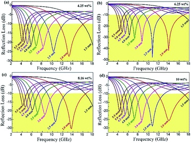 | ||
| Fig. 7 The reflection loss of rGO/LSMO composites with the thickness of 1.5–5.5 mm; (a) 4.25 wt%, (b) 6.25 wt%, (c) 8.16 wt%, (d) 10.0 wt%. | ||
It is worth noting that microwave absorption peaks shifted toward the low frequency regions as the thickness of the absorber increased from 1.5 to 5.5 mm. This phenomenon can be explained by the 1/4 wavelength equation:42,43
 | (6) |
 | (7) |
It is noticeable that the value of α increases with rise in the concentration of rGO, which is in accordance with the fact the delaminated Ti3C2Tx nanosheets.45
Three factors affect absorbing properties, including dielectric loss, magnetic loss, and impedance matching characteristic. Firstly, the two-dimensional sheet of rGO with a large specific surface area formed a conductive network in the composites, resulting in high dielectric loss tangent. After the hydrothermal reduction, GO cannot be deoxidized completely and its electrical properties cannot be restored to the level of the graphite. However, too high a permittivity of absorber is harmful to the impedance match and results in strong reflection and weak absorption. Thus, the electrical properties of composites are good enough for microwave absorption. Secondly, the magnetic loss tangent was attributed to the outstanding magnetic properties of LSMO, including domain wall resonance, natural resonance and hysteresis loss. In addition, due to the difference in complex permittivity between rGO and LSMO, interface scattering would be generated, leading to more microwave absorption.
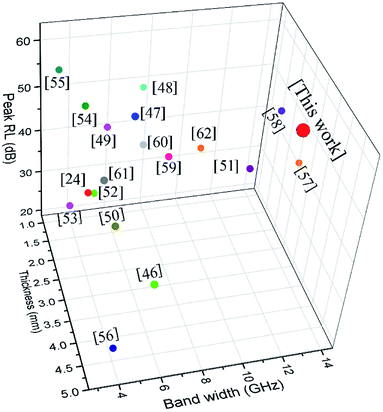
Some other similar absorbents are presented in Table 1, covering LSMO and graphene-based materials. All the corresponding materials have enhanced microwave absorption abilities. Among these specific absorbers, the synthesized rGO/LSMO shows the first-class performance for the broader bandwidth and thinner thickness, as shown in Fig. 8.
| Composites | Loading (wt%) | Thickness (mm) | RL (dB) | Band width (GHz) | Range (GHz) | Ref. |
|---|---|---|---|---|---|---|
| rGO/LSMO | 70 | 2.5 | 47.9 | 14.5 | 3.5–18.0 | This work |
| rGO/LSMO | 60 | 2.5 | 38.8 | 4.0 | 14–18.0 | 24 |
| rGO/NiFe2O4 | 70 | 5.0 | 42.0 | 5.3 | 11.6–17.2 | 46 |
| rGO/CoFe2O4 | 50 | 2.8 | 57.7 | 5.8 | 8.3–14.1 | 47 |
| rGO/CoFe2O4/PVP | 50 | 2.0 | 56.8 | 6.8 | 10.6–17.4 | 48 |
| rGO/SrFe12O19/PANI | 50 | 1.5 | 45.0 | 5.5 | 12.8–18.0 | 49 |
| rGO/Fe3O4 | 50 | 3.9 | 44.6 | 4.3 | 12.2–16.5 | 50 |
| rGO/Fe3O4/PANI | 20 | 3.0 | 45.0 | 11.4 | 6.6–18.0 | 51 |
| rGO/Y-Fe2O3 | 30 | 2.0 | 34.2 | 4.6 | 10.6–15.2 | 52 |
| rGO/Co3O4/MDCF | 10 | 2.0 | 31.9 | 3.4 | 10.6–14.0 | 53 |
| rGO/Co3O4/SiO2 | 50 | 1.8 | 52.6 | 4.2 | 8.2–12.4 | 54 |
| rGO/CoNi | 7 | 0.8 | 53.3 | 3.5 | 14.5–18.0 | 55 |
| rGO/NiCoP | 50 | 4.4 | 20.6 | 4.1 | 13.9–18.0 | 56 |
| rGO/FeCo | 50 | 2.5 | 40.2 | 14.6 | 3.4–18.0 | 57 |
| rGO/FeCo | 30 | 2.5 | 52.9 | 13.2 | 4.8–18.0 | 58 |
| rGO/FeCO3 | 60 | 2.4 | 44.5 | 7.9 | 10.1–18.0 | 59 |
| rGO/Ni | 10 | 2.4 | 47.9 | 6.6 | 10.0–16.6 | 60 |
| rGO/Ni | 20 | 3.5 | 51.1 | 4.0 | 7.3–11.3 | 61 |
| rGO/Co | 15 | 1.9 | 41.1 | 10.0 | 8.0–18.0 | 62 |
Conclusions
Reduced graphene oxide/La0.7Sr0.3MnO3 (rGO/LSMO) composites were successfully prepared by hydrothermal method. Studies show that 6.25 wt% of rGO/LSMO in wax matrix exhibits high values of reflection loss (>10 dB) over a wide frequency range from 11.9 to 16.9 GHz (5 GHz bandwidth) at a thickness of 2.0 mm, and the strongest reflection loss is −47.9 dB at 10.7 GHz at a thickness of 2.5 mm. Moreover, the effective absorption bandwidth with the reflection loss below −10 dB is up to 14.5 GHz, ranged from 3.5 to 18 GHz for the composites with the thickness in 1.5–5.5 mm, due to a synergism between dielectric loss of rGO and magnetic loss of magnetic LSMO, which is an interesting and valuable exploration in the physical application of rGO and LSMO.Conflicts of interest
There are no conflicts to declare.Acknowledgements
This research was supported by the Natural Science Foundation of China (No. 51772150, 51902154), Key Research and Development Program of Jiangsu Province (No. BK20160093, BE2018008-1), the China Postdoctoral Science Foundation (No. 2017-62-1738).Notes and references
- R. C. Che, L. M. Peng, X. F. Duan, Q. Chen and X. L. Liang, Adv. Mater., 2004, 16(5), 401–405 CrossRef CAS.
- M. K. Han, X. W. Yin, L. Kong, M. Li, W. Y. Duan, L. T. Zhang and L. F. Cheng, J. Mater. Chem. A, 2014, 2(39), 16403–16409 RSC.
- M. S. Cao, C. Han, X. X. Wang, M. Zhang, Y. L. Zhang, J. C. Shu, H. J. Yang, X. Y. Fang and J. Yuan, J. Mater. Chem. C, 2018, 6, 4586–4602 RSC.
- X. Jian, X. Y. Xiao, L. J. Deng, W. Tian, X. Wang, N. Mahmood and S. X. Dou, ACS Appl. Mater. Interfaces, 2018, 10, 9369–9378 CrossRef CAS PubMed.
- L. B. Kong, Z. W. Li, L. Liu, R. Huang, M. Abshinova and Z. H. Yang, Int. Mater. Rev., 2013, 58(4), 203–259 CrossRef CAS.
- Y. Liu, Y. Zhang, C. Zhang, B. Huang and X. Liu, J. Mater. Chem. C, 2018, 6(35), 9399–9409 RSC.
- Z. C. Mo, R. L. Yang, D. W. Lu, L. L. Yang, Q. M. Hu and H. B. Li, Carbon, 2019, 144, 433–439 CrossRef CAS.
- M. S. Cao, W. L. Song, Z. L. Hou, B. Wen and J. Yuan, Carbon, 2010, 48, 788–796 CrossRef CAS.
- B. Wen, M. S. Cao, M. M. Lu, W. Q. Cao, H. L. Shi, J. Liu, X. X. Wang, H. B. Lin, X. Y. Fang, W. Z. Wang and J. Yuan, Adv. Mater., 2014, 26, 3484–3489 CrossRef CAS PubMed.
- H. L. Lv, Y. H. Guo, Z. H. Yang, Y. Cheng, L. Y. Wang, B. S. Zhang, Y. Zhao, Z. C. Xu and G. B. Ji, J. Mater. Chem. C, 2017, 5(3), 491–512 RSC.
- O. Balci, E. O. Polat, N. Kakenov and C. Kocabas, Nat. Commun., 2015, 6(1–9), 6628 CrossRef CAS PubMed.
- X. F. Yu, L. Wang, J. W. Liu, S. Y. Xue, L. T. Yang, X. Li, J. Zhang, L. S. Xing, G. Y. Chen, M. Wang and R. C. Che, J. Mater. Chem. C, 2019, 7, 2943–2953 RSC.
- L. Wang, J. Zhang, M. Wang and R. C. Che, J. Mater. Chem. C, 2019, 7, 11167–11176 RSC.
- C. Wang, X. J. Han, P. Xu, X. L. Zhang, Y. C. Du and S. R. Hu, Appl. Phys. Lett., 2011, 98(7), 072906 CrossRef.
- B. Quan, X. H. Liang, G. B. Ji, J. Lv, S. S. Dai, G. Y. Xu and Y. W. Du, Carbon, 2018, 129, 310–320 CrossRef CAS.
- S. Q. Jiao, M. Z. Wu, X. X. Yu, H. B. Hu, Z. M. Bai, P. Dai, T. T. Jiang, H. Bi and G. Li, Mater. Res. Bull., 2018, 108, 89–95 CrossRef CAS.
- A. M. Haghiri-Gosnet, J. Wolfman, B. Mercey, C. Simon, P. Lecoeur and M. Korzenski, J. Appl. Physiol., 2000, 88(7), 4257–4264 CrossRef CAS.
- G. Q. Gong, C. Canedy, G. Xiao, J. Z. Sun, A. Gupta and W. J. Gallagher, Appl. Phys. Lett., 1995, 67, 1783 CrossRef CAS.
- R. Ramamoorthy, S. A. Akbar and P. K. Dutta, Sens. Actuators, B, 2006, 113(1), 162–168 CrossRef CAS.
- M. C. Wu, C. M. Chuang, J. F. Lin, Y. C. Huang, F. C. Yang and F. S. Wei, J. Mater. Res., 2009, 24(2), 395–404 CrossRef.
- M. P. De Jong, V. A. Dediu, C. Taliani and W. R. Salaneck, J. Appl. Phys., 2010, 94(11), 7292–7296 CrossRef.
- K. L. Yan, R. H. Fan, Z. C. Shi, M. Chen, L. Qian and Y. L. Wei, J. Mater. Chem. C, 2014, 2(6), 1028–1033 RSC.
- J. Lloyd-Hughes, C. D. Mosley, S. P. Jones, M. R. Lees, A. Chen and Q. X. Jia, Nano Lett., 2017, 17(4), 2506–2511 CrossRef CAS PubMed.
- S. Dai, B. Quan, B. Zhang, X. Liang and G. B. Ji, Dalton Trans., 2019, 48, 2359–2366 RSC.
- D. F. He, L. M. Shen, X. Zhang, Y. Wang, N. Z. Bao and H. Kung, AIChE J., 2014, 60(8), 2757–2764 CrossRef CAS.
- C. Li, Y. X. Shi, X. Chen, D. F. He, L. M. Shen and N. Z. Bao, Chem. Eng. Sci., 2018, 176, 319–328 CrossRef CAS.
- D. F. He, L. X. Li, F. J. Bai, C. Y. Zha, L. M. Shen and H. H. Kung, Chem.–Eur. J., 2016, 22(13), 4454–4459 CrossRef CAS PubMed.
- P. He, X. X. Wang, Y. Z. Cai, J. C. Shu, Q. L. Zhao, J. Yuan and M. S. Cao, Nanoscale, 2019, 11, 6080–6088 RSC.
- P. He, M. S. Cao, Y. Z. Cai, J. C. Shu, W. Q. Cao and J. Yuan, Carbon, 2020, 157, 80–89 CrossRef CAS.
- H. J. Yang, J. Yuan, Y. Li, Z. L. Hou, H.-B. Jin, X. Y. Fang and M. S. Cao, Solid State Commun., 2013, 163, 1–6 CrossRef CAS.
- C. Wang, X. J. Han, P. Xu, J. Y. Wang, Y. C. Du, X. H. Wang, W. Qin and T. Zhang, J. Phys. Chem. C, 2010, 114, 3196–3203 CrossRef CAS.
- L. J. Deng and M. G. Han, Appl. Phys. Lett., 2007, 91, 023119 CrossRef.
- Y. J. Chen, P. Gao, R. X. Wang, C. L. Zhu, L. J. Wang, M. S. Cao and H. B. Jin, J. Phys. Chem. C, 2009, 113, 10061–10064 CrossRef CAS.
- X. L. Shi, M. S. Cao, J. Yuan and X. Y. Fang, Appl. Phys. Lett., 2009, 95, 163108 CrossRef.
- J. H. Zhou, J. P. He, G. X. Li, T. Wang, D. Sun, X. C. Ding, J. Q. Zhao and S. C. Wu, J. Phys. Chem. C, 2010, 114, 7611–7617 CrossRef CAS.
- S. C. Chiu, H. C. Yu and Y. Y. Li, J. Phys. Chem. C, 2010, 114, 1947–1952 CrossRef CAS.
- D. Li, Y. Feng, D. S. Pan, L. W. Jiang, Z. M. Dai, S. J. Li, Y. Wang, J. He, W. Liu and Z. D. Zhang, RSC Adv., 2016, 6, 73020–73027 RSC.
- Y. R. Feng, X. Guo, H. Y. Gong, Y. J. Zhang, Y. Liu, X. Lin and J. J. Mao, Ceram. Int., 2018, 44, 10420–10425 CrossRef CAS.
- B. Alavikia, A. Kabiri and O. M. Ramahi, J. Opt. Soc. Am. A, 2015, 32(4), 522–532 CrossRef PubMed.
- N. Zhu, H. Ji, P. Yu, J. Q. Niu, M. U. Farooq and M. W. Akram, Nanomaterials, 2018, 8(10), 810 CrossRef PubMed.
- H. J. Yang, M. S. Cao, Y. Li, H. L. Shi, Z. L. Hou and X. Y. Fang, Adv. Opt. Mater., 2014, 2(3), 214–219 CrossRef.
- X. Qiu, L. Wang and H. Zhu, Nanoscale, 2017, 9, 7408 RSC.
- L. X. Wang, P. Zhou, Y. Guo, J. Zhang, X. Qiu and Y. K. Guan, RSC Adv., 2019, 9, 9718 RSC.
- P. He, M. S. Cao, J. C. Shu, Y. Z Cai, X. X. Wang, Q. L. Zhao and J. Yuan, ACS Appl. Mater. Interfaces, 2019, 11, 12535–12543 CrossRef CAS PubMed.
- M. S. Cao, X. X. Wang, W. Q. Cao, X. Y. Fang, B. Wen and J. Yuan, Small, 2018, 14(1–8), 1800987 CrossRef PubMed.
- J. Z. He, X. X. Wang, Y. L. Zhang and M. S. Cao, J. Mater. Chem. C, 2016, 4, 7130 RSC.
- Y. Liu, Z. Chen, Y. Zhang, R. Feng, X. Chen, C. X. Xiong and L. J. Dong, ACS Appl. Mater. Interfaces, 2018, 10, 13860–13868 CrossRef CAS PubMed.
- T. Zhu, S. C. Chang, Y. F. Song, M. Lahoubi and W. Wang, Chem. Eng. J., 2019, 373, 755–766 CrossRef CAS.
- J. H. Luo, P. Shen, W. Yao, C. F. Jiang and J. G. Xu, Nanoscale Res. Lett., 2016, 11, 141 CrossRef PubMed.
- M. Zong, Y. Huang, Y. Zhao, X. Sun, C. Qu and D. Luo, RSC Adv., 2013, 3(45), 23638 RSC.
- Y. B. Ma, Y. Y. Zhou, Y. Y. Sun, H. Chen, Z. Y. Xiong, X. L. Li, L. Y. Shen and Y. Q. Liu, J. Alloys Compd., 2019, 796, 120–130 CrossRef CAS.
- S. S. Wang, Q. Z. Jiao, X. F. Liu, Y. C. Xu, Q. Shi, S. Yue, Y. Zhao, H. B. Liu, C. H. Feng and D. X. Shi, ACS Sustainable Chem. Eng., 2019, 7(7), 7004–7013 CrossRef CAS.
- Y. Li, S. Li, T. Zhang, L. L. Shi, S. T. Liu and Y. Zhao, J. Alloys Compd., 2019, 792, 424–431 CrossRef CAS.
- J. R. Ma, J. C. Shu, W. Q. Cao, M. Zhang, X. X. Wang, J. Yuan and M. S. Cao, Composites, Part B, 2019, 166, 187–195 CrossRef CAS.
- H. B. Zhao, J. B. Cheng, J. Y. Zhu and Y. Z. Wang, J. Mater. Chem. C, 2019, 7, 441–448 RSC.
- Y. J. Wang, Y. Sun, Y. Zong, L. X. Zhang, Y. Y. Lan, H. N. Xing, X. H. Li and X. L. Zheng, J. Solid State Chem., 2019, 277, 201–208 CrossRef CAS.
- X. Li, J. Feng, Y. Du, J. Bai, H. Fan and H. Zhang, J. Mater. Chem. A, 2015, 3(10), 5535–5546 RSC.
- Y. Wang, X. Gao, C. H. Lin, L. Y. Shi, X. H. Li and G. L. Wu, J. Alloys Compd., 2019, 785, 765–773 CrossRef CAS.
- W. Huang, S. C. Wei, Y. J. Wang, B. Wang, Y. Liang, Y. W. Huang and B. S. Xu, Materials, 2019, 12, 2206 CrossRef PubMed.
- J. M. Tang, N. Liang, L. Wang, J. Li, G. Tian, D. Zhang, S. H. Feng and H. J. Yue, Carbon, 2019, 152, 575–586 CrossRef CAS.
- K. Xu, W. H. Ma, Y. N. Liu, Y. F. Bai, J. W. Xue, Y. Liu, G. Z. Zhao and Y. Q. Liu, J. Mater. Sci.: Mater. Electron., 2019, 30, 9133–9142 CrossRef CAS.
- H. Y. Liao, D. Li, C. Zhou and T. Liu, J. Alloys Compd., 2019, 782, 556–565 CrossRef CAS.
Footnote |
| † Electronic supplementary information (ESI) available. See DOI: 10.1039/c9ra09474a |
| This journal is © The Royal Society of Chemistry 2019 |


