 Open Access Article
Double-layer carbon protected CoS2 nanoparticles as an advanced anode for sodium-ion batteries†
Xiang Yao,
Hui Cheng,
Yuping Huang,
Zhouyang Jiang,
Qingyue Han and
Suqing Wang *
*
School of Chemistry and Chemical Engineering, Guangdong Provincial Key Lab of Green Chemical Product Technology, South China University of Technology, Guangzhou 510640, P. R. China. E-mail: cesqwang@scut.edu.cn
First published on 11th December 2019
Abstract
Cobalt disulfides with high theoretical capacity are regarded as appropriate anode materials for sodium ion batteries (SIBs), but their intrinsically low conductivity and large volume expansion lead to a poor electrochemical performance. In this work, graphitic carbon coated CoS2 nanoparticles are encapsulated in bamboo-like carbon nanotubes by pyrolysis and sulfidation process. Graphitic carbon can improve the electrical conductivity and prevent the agglomeration of CoS2 nanoparticles. Meanwhile, bamboo-like carbon nanotubes can serve as conductive skeleton frames to provide rapid and constant transport pathways for electrons and offer void space to buffer the volume change of CoS2 nanoparticles. The advanced anode material exhibits a long-term capacity of 432.6 mA h g−1 at 5 A g−1 after 900 cycles and a rate capability of 419.6 mA h g−1 even at 10 A g−1 in the carbonate ester-based electrolyte. This avenue can be applicable for preparing other metal sulfide/carbon anode materials for sodium-ion batteries.
Introduction
The energy shortage and environmental pollution have disrupted global development. Renewable energy has been urgently used to substitute fossil fuel. Although lithium-ion batteries (LIBs) and lithium metal batteries (LMBs) have been developed in fundamental research as an industrial application, the fewer lithium resources on Earth and hence their high cost restrict the long-term usage of LIBs.1–3 However, sodium-ion batteries (SIBs) have lowered the concerns, thanks to the abundant sodium sources and cheaper sodium salt.4,5 On the other hand, commercial graphite anode is not suitable for SIBs because its interlayer spacing is smaller than the diameter of Na+.6,7 Thus, exploring suitable anode materials is urgently required for SIBs. In contrast to transition metal oxides, transition metal sulfides are kinetically favorable for conversion reactions, which makes them have more potential with other anode materials.8,9 Furthermore, they possess high specific capacity and easily-controlled morphology and are regarded as prospective anode materials for SIBs.10 More importantly, compared with other cobalt sulfides (CoS, Co3S4, and Co9S8),11 CoS2 has a great advantage in virtue of high theoretical capacity of 872 mA h g−1 because of a four-electron conversion reaction represented as CoS2 + 4Na+ + 4e− ↔ Co + 2Na2S.12 Owing to the drastic volume change of conversion-type mechanism, CoS2 always exhibits a poor cycling performance.13 Numerous researches have been dedicated to mitigate the issue. Downsizing the particle size is one common way to decrease the length of ion diffusion and relieve the pressure of volume expansion.14 Liu et al. reported that CoS2 with hollow microstructures was used as an anode for SIBs, which retained 690 mA h g−1 at 1 A g−1 after 100 cycles.15 Another effective way is to incorporate CoS2 particles with a carbon material, which can not only provide electron transport pathways but also buffer volume expansion. Zhang et al. revealed the production of CoS2 nanoparticles with a spongy carbon matrix and also stated that the SIB anode material displayed a rate capability of 330 mA h g−1 at 0.5 A g−1 after 60 cycles.16 Cheng et al. bound nanosized CoS2 in graphene and the material could retain 394 mA h g−1 at 1 A g−1 after 2500 cycles, which can be attributed to the highly conductive graphene network and short diffusion length of electrons and ions within the electrode.17 Xie et al. displayed the preparation of CoS2 nanoparticles enclosed in rGO, and the material can reach to about 400 mA h g−1 at 0.1 A g−1 after 100 cycles.18 These studies suggested that a reasonable electrode structure design and incorporation of CoS2 nanoparticles with a carbon material can exhibit good sodium storage performance. However, an unstable structure of electrode in carbon material and serious side effects of nanoparticles and electrolyte could impair the performance of CoS2.19–21Here, we prepared a double-layered carbon structure as the anode material in which graphitic carbon-coated CoS2 nanoparticles were encapsulated in bamboo-like carbon nanotubes (CoS2@GC@B-CNT). In this preparation, graphitic carbon (GC) could serve as an appropriate coating layer because the electrical conductivity of GC is higher than that of amorphous carbon layers and the GC layer can prevent the agglomeration of CoS2 nanoparticles. Furthermore, bamboo-like carbon nanotubes (B-CNTs) serve as conductive skeleton frames to provide continuous and fast transport pathways for electrons and offer sufficient voids to buffer the volume expansion of CoS2 nanoparticles, which could maintain a steady structure during the sodiation/desodiation process. Therefore, the obtained CoS2@GC@B-CNT showed excellent long-term cycling performance and high rate capability when used as an anode in a carbonate ester-based electrolyte for SIBs.
Experimental
Material synthesis
The CoS2@GC@B-CNT samples were obtained by a two-step formation process. First, cobalt nitrate hexahydrate (0.8 g), glucose (0.1 g) and melamine (8.0 g) were blended together in 50 mL deionized water under stirring for 1 h. The solution was dried at 80 °C for 1 h and annealed at 800 °C for 2 h in Ar gas to produce Co@GC@B-CNT. Then, 0.1 g of Co@GC@B-CNT and an appropriate amount of thiourea were placed in two separate crucible boats and treated at 450 °C for 4 h with thiourea at the upstream side in the pipe furnace under Ar atmosphere. In order to prepare B-CNT, the CoS2@GC@B-CNT samples were treated in 6.0 M HCl solution for 8 h under stirring, washed by deionized water, and dried at 80 °C for 12 h. To gain bare CoS2, 1.0 g of cobalt nitrate hexahydrate and an appropriate amount of thiourea powder were annealed by the same protocol as for the synthesis of CoS2@GC@B-CNT. For the CoS2/CNT composite, 0.0581 g CoS2 was mixed with 0.0419 g commercial multi-walled carbon nanotube.Material characterization
The structures were detected through an XRD (Bruker D8 Advanced) operated within the 2θ range of 10–70°. The percentage of carbon in CoS2@GC@B-CNT was measured by Thermogravimetric Analysis. The samples were oxidized and annealed from 30 to 850 °C in air by a TG equipment (NETZSCH STA44C). The morphology was studied by SEM (HITACHI-SU8220) and TEM (JEM-2100F) with an EDS elemental mapping. XPS was tested by an ESCALAB 250 X-ray photoelectron spectrometer. N2 adsorption/desorption experiments were performed on a Micromeritics Analyzer ASAP 2460 equipment.Electrochemical tests
The anode electrodes were obtained by mixing the active material, Super-P and polyvinylidene fluoride (8![[thin space (1/6-em)]](https://www.rsc.org/images/entities/char_2009.gif) :
:![[thin space (1/6-em)]](https://www.rsc.org/images/entities/char_2009.gif) 1
1![[thin space (1/6-em)]](https://www.rsc.org/images/entities/char_2009.gif) :
:![[thin space (1/6-em)]](https://www.rsc.org/images/entities/char_2009.gif) 1 by weight). The slurry was coated on a Cu foil and dried in a vacuum oven at 80 °C for 12 h. The mass loading of active materials based on the total weight of CoS2 and carbon was about 1.0–1.5 mg cm−2. The separator was a Whatman (GF/B) glass fiber. The electrolyte was 1 M NaClO4 in a mixture of ethylene carbonate and diethyl carbonate (v/v = 1
1 by weight). The slurry was coated on a Cu foil and dried in a vacuum oven at 80 °C for 12 h. The mass loading of active materials based on the total weight of CoS2 and carbon was about 1.0–1.5 mg cm−2. The separator was a Whatman (GF/B) glass fiber. The electrolyte was 1 M NaClO4 in a mixture of ethylene carbonate and diethyl carbonate (v/v = 1![[thin space (1/6-em)]](https://www.rsc.org/images/entities/char_2009.gif) :
:![[thin space (1/6-em)]](https://www.rsc.org/images/entities/char_2009.gif) 1) with 5 wt% fluoroethylene carbonate. Sodium discs were the opposite electrode. Coin cells (CR 2032) were fabricated in an Ar-filled glovebox. Constant current charge/discharge measurements were checked on a battery test station (Neware Electronic Co.) from 0.01 to 3.00 V. CV was performed on an electrochemical workstation (CHI760D) between 0.01 and 3.00 V at a scan rate of 0.2 mV s−1. EIS was performed at frequencies ranging from 0.01 to 0.1 MHz.
1) with 5 wt% fluoroethylene carbonate. Sodium discs were the opposite electrode. Coin cells (CR 2032) were fabricated in an Ar-filled glovebox. Constant current charge/discharge measurements were checked on a battery test station (Neware Electronic Co.) from 0.01 to 3.00 V. CV was performed on an electrochemical workstation (CHI760D) between 0.01 and 3.00 V at a scan rate of 0.2 mV s−1. EIS was performed at frequencies ranging from 0.01 to 0.1 MHz.
Results and discussion
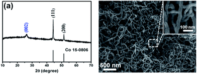
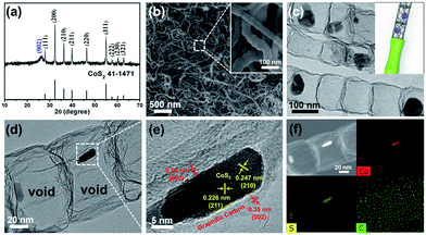
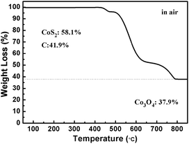
The CoS2@GC@B-CNT anode material was obtained by a two-step formation process (Scheme 1). In the first step, cobalt nitrate hexahydrate, glucose, and melamine were annealed at 800 °C to produce Co@GC@B-CNT. The XRD pattern is displayed in Fig. 1a, in which the diffraction peaks are in good accordance with metallic Co. Then, CoS2@GC@B-CNT was acquired after thermal treatment via a sulfidation process. From the XRD pattern of CoS2@GC@B-CNT (Fig. 2a), the major peaks of CoS2@GC@B-CNT corresponded to CoS2. The wide diffraction peak at 26.1° is observed and corresponds to the (002) plane of graphite. The morphology of the carbon nanotubes is unchanged before and after the sulfidation process (Fig. 1b and 2b). The TEM images confirm that CoS2 nanoparticles are completely encapsulated in B-CNT (Fig. 2c and d) and the void in the B-CNT could buffer the volume change of CoS2 in the course of the conversion reaction. Furthermore, B-CNT could provide facile electronic and ionic transport, improving the conductivity of the material. Fig. 2e shows that the CoS2 nanoparticles are surrounded by GC, and the lattice spacing of 0.247 and 0.226 nm associate with the interplanar distance of the (210) and (211) planes, respectively. In the meantime, the lattice spacing of 0.35 nm ascribes to the interplanar distance of the (002) plane of carbon. The GC originating from the catalysis of Co nanocrystals during the thermal treatment can improve the electrical conductivity and prevent the agglomeration of CoS2 nanoparticles.22–25 The elemental mapping images (Fig. 2f) further demonstrate that the CoS2 nanoparticles were encapsulated in B-CNT. The carbon content in CoS2@GC@B-CNT is confirmed to be 41.9% (Fig. 3). For comparison, bare CoS2 particles and CoS2 composite mixed with commercial CNT (CoS2/CNT) were prepared and the XRD patterns are displayed in Fig. S1.† To characterize the porous structure in detail, N2 adsorption–desorption measurements were carried out (Fig. 4). The Co@GC@B-CNT possesses a mesoporous structure and the size of the majority of pores is about 2.0 nm (Fig. 4a). After the sulfidation process, the pore size distribution curve of the CoS2@GC@B-CNT displays that the pore size of samples is about 3.5 nm (Fig. 4b). The increased pore volume is due to the etching effect of H2S derived from thiourea decomposition during the sulfidation process, which can expand the contact area between the electrode and electrolyte, contributing to the sodiation/desodiation process.26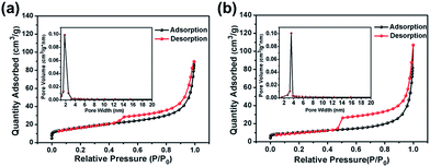 | ||
| Fig. 4 Nitrogen adsorption–desorption isotherm and pore size distribution of (a) Co@GC@B-CNT; (b) CoS2@GC@B-CNT. | ||
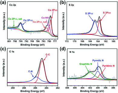
The surface chemistry of CoS2@GC@B-CNT was analysed by XPS (Fig. S2†). The Co 2p spectrum (Fig. 5a) is divided into two groups of peaks. The first group of peaks at 779.2, 780.0, and 781.4 eV is associated with the spin–orbit peaks of Co 2p3/2. The peak at 779.2 eV is assigned to Co2+ and 781.4 eV is put down to the satellite peak of Co 2p3/2. Additionally, the peak at 780.0 eV is attributed to the existence of Co–NH bonds. Another group of peaks at 795.0 is assigned to the Co 2p1/2 level and 799.0 eV corresponds to its satellite peak.27 The S 2p spectrum is made up of two peaks (Fig. 5b), the peak at 163.6 eV is assigned to S 2p3/2, while the peak at 164.8 eV is contributed by S 2p1/2.28 The C 1s spectrum includes two fitting peaks (Fig. 5c); they are C–C (284.8 eV) and C–N (285.8 eV).29,30 On the basis of XPS analysis, it can be confirmed that CoS2 nanoparticles have been favorably prepared, which is unanimous in the previous XRD and TEM analyses. Fig. 5d shows that the N 1s spectrum evinces the attendance of pyridinic (399.3 eV), pyrrolic (400.0 eV) and graphitic (401.9 eV) types of N. N doping could introduce more defective sites, which boost the sodium storage performance.31
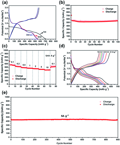
The CV test of CoS2@GC@B-CNT was conducted at 0.2 mV s−1 (Fig. S3†). The oxidation and reduction peaks are presented in the first cycle. The oxidation peaks are put down to the production of NaxCoS2 and CoS2. Moreover, the reduction peaks in the first cycle are different from those in the later cycles, which mainly ascribes to the activation process. In the second and third cycles, the peaks (0.89 and 1.36 V) stem from the conversion reaction (CoS2 + 4Na → Co + 2Na2S) and the peak at 0.52 V implies that Na+ intercalates into the GC. Fig. 6a displays first three charge and discharge curves. CoS2@GC@B-CNT delivers a reversible capacity of about 550 mA h g−1 at 0.1 A g−1. To clarify the capacity contribution of B-CNT, CoS2@GC@B-CNT was treated by an acid to remove CoS2. The XRD pattern (Fig. S4a†) shows that most of the CoS2 particles were removed by HCl and the morphology of the carbon nanotubes is not varied (Fig. S4b†). The electrochemical performance of individual B-CNT was measured at 0.1 A g−1 (Fig. S4c and d†); the capacity was approximately 150 mA h g−1 during 100 cycles. The carbon content of CoS2@GC@B-CNT is 41.9% (Fig. 3). Through calculation, the capacity contribution of carbon is about 62 mA h g−1, which indicates that the main capacity of CoS2@GC@B-CNT is contributed to CoS2. In Fig. 6b and S5,† the cycling performances of CoS2@GC@B-CNT, CoS2/CNT and bare CoS2 are measured at 0.1 A g−1. It is obvious that the cycling stability of CoS2@GC@B-CNT is the best among them. The CoS2/CNT and bare CoS2 present significant capacity fading during cycling, which indicates that CoS2 is the main capacity source of CoS2@GC@B-CNT.
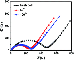
Fig. 6c shows the rate performance of CoS2@GC@B-CNT. CoS2@GC@B-CNT shows the discharge capacities of 564.3, 518.5, 486.5, 471.0, 455.9, 438.0, 419.6 mA h g−1 at the rates of 0.1, 0.2, 0.5, 1, 2, 5 and 10 A g−1, respectively. The CoS2@GC@B-CNT electrode can hold 512.6 mA h g−1 at 0.1 A g−1. Fig. 6d displays the relevant charge and discharge curves of CoS2@GC@B-CNT, which suggests its superior rate capability. In contrast, CoS2/CNT and bare CoS2 electrodes show much lower capacities (Fig. S6†). The CoS2/CNT and bare CoS2 samples retained capacities of 58.9 and 36.2 mA h g−1 at 1 A g−1, respectively. Fig. 6e exhibits a long-term cycling property of CoS2@GC@B-CNT, which demonstrates a capacity of 432.6 mA h g−1 after 900 cycles at 5 A g−1 and the capacity retention of 95.9%. In particular, the electrochemical property of CoS2@GC@B-CNT is eminent among other cobalt sulfide-based electrodes in the carbonate ester-based electrolyte for SIBs (Table S1†). The outstanding electrochemical performance is ascribed to the novel structure design of CoS2@GC@B-CNT. The synergetic actions of GC and B-CNT can improve the electrical conductivity, prevent the particle agglomeration and maintain structural stability of CoS2@GC@B-CNT during the sodiation/desodiation process. The EIS tests were investigated before and after different numbers of cycles. The Nyquist plots of the CoS2@GC@B-CNT electrode exhibit a semicircle and a following linear slope (Fig. 7). The semicircle region ascribes to the charge transfer resistance (Rct).32 The Rct decreases after 50 cycles. Furthermore, after 100 cycles, the Rct displays just a small increase, suggesting a stable structure and good conductivity of the electrode.33,34 The reason can be ascribed to the composite electrode decorated with GC and B-CNT.
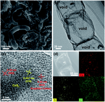
To investigate the cause of the good cycling stability of CoS2@GC@B-CNT electrode, the cells were disassembled at 0.1 A g−1 after 100 cycles. The CoS2@GC@B-CNT sustains structural integrity (Fig. 8a), further confirming the outstanding cycling performance of CoS2@GC@B-CNT. The detailed inner structure is shown in Fig. 8b where the CoS2 nanoparticles are encapsulated in B-CNT. Fig. 8c displays that the CoS2 nanoparticles are still surrounded by GC, which confirms that GC is stable during the charge/discharge process. Therefore, high stability is observed due to the double protection of GC and B-CNT. The elemental mapping images give the elemental distribution of Co, S, and C, which indicates that the CoS2 particles are still encapsulated in B-CNT (Fig. 8d). In contrast, CoS2/CNT and bare CoS2 present large volume expansion during the sodiation/desodiation process (Fig. S7†), which results in poor electrochemical properties.
Conclusions
In summary, CoS2@GC@B-CNT was successfully synthesized by pyrolysis and sulfidation process. Double-layer carbon can improve the electrical conductivity and maintain structural stability during the sodiation/desodiation process, which can enhance electrochemical performances. CoS2@GC@B-CNT displayed a high rate capability of 419.6 mA h g−1 at 10 A g−1 and eminent long-term cycling performance with 95.9% capacity retention at 5 A g−1 after 900 cycles. This avenue could be widely applied for preparing other anode materials using metal sulfides and carbon for high-performance SIBs.Conflicts of interest
There are no conflicts to declare.Acknowledgements
This work was financially supported by the National Natural Science Foundation of China (No. 21576100, and 21776098), National Key R&D Program of China: (No. 2016YFA0202600), Guangdong Natural Science Funds for Distinguished Young Scholar (2017A030306022) and Pearl River S&T Nova Program of Guangzhou (201610010062) and the Fundamental Research Funds for the Central Universities.Notes and references
- H. Pan, Y.-S. Hu and L. Chen, Energy Environ. Sci., 2013, 6, 2338–2360 RSC.
- X. Chen, W. He, L.-X. Ding, S. Wang and H. Wang, Energy Environ. Sci., 2019, 12, 938–944 RSC.
- Z. Jiang, H. Xie, S. Wang, X. Song, X. Yao and H. Wang, Adv. Energy Mater., 2018, 8, 1801433 CrossRef.
- D. Wang, Q. Wei, J. Sheng, P. Hu, M. Yan, R. Sun, X. Xu, Q. An and L. Mai, Phys. Chem. Chem. Phys., 2016, 18, 12074–12079 RSC.
- Y. An, J. Feng, L. Ci and S. Xiong, RSC Adv., 2016, 6, 103579–103584 RSC.
- Y. Zhang, N. Wang, P. Xue, Y. Liu, B. Tang, Z. Bai and S. Dou, Chem. Eng. J., 2018, 343, 512–519 CrossRef CAS.
- S. Liu, J. Feng, X. Bian, J. Liu and H. Xu, Energy Environ. Sci., 2016, 9, 1229–1236 RSC.
- Q. Zhou, L. Liu, Z. Huang, L. Yi, X. Wang and G. Cao, J. Mater. Chem. A, 2016, 4, 5505–5516 RSC.
- X. Song, X. Li, Z. Bai, B. Yan, D. Li and X. Sun, Nano Energy, 2016, 26, 533–540 CrossRef CAS.
- Z. Hu, Q. Liu, S.-L. Chou and S.-X. Dou, Adv. Mater., 2017, 29, 1700606 CrossRef PubMed.
- X. Wang, Y. Chen, Y. Fang, J. Zhang, S. Gao and X. Lou, Angew. Chem., Int. Ed., 2019, 58, 2675–2679 CrossRef CAS PubMed.
- Z. Shadike, M.-H. Cao, F. Ding, L. Sang and Z. Fu, Chem. Commun., 2015, 51, 10486–10489 RSC.
- S. Qi, D. Wu, Y. Dong, J. Liao, C. W. Foster, C. O'Dwyer, Y. Feng, C. Liu and J. Ma, Chem. Eng. J., 2019, 370, 185–207 CrossRef CAS.
- F. Zhao, S. Shen, L. Cheng, L. Ma, J. Zhou, H. Ye, N. Han, T. Wu, Y. Li and J. Lu, Nano Lett., 2017, 17, 4137–4142 CrossRef CAS PubMed.
- X. Liu, K. Zhang, K. Lei, F. Li, Z. Tao and J. Chen, Nano Res., 2016, 9, 198–206 CrossRef CAS.
- Y. Zhang, N. Wang, C. Sun, Z. Lu, P. Xue, B. Tang, Z. Bai and S. Dou, Chem. Eng. J., 2018, 332, 370–376 CrossRef CAS.
- X. Cheng, D. Li, F. Liu, R. Xu and Y. Yu, Small Methods, 2018, 1800170 Search PubMed.
- K. Xie, L. Li, X. Deng, W. Zhou and Z. Shao, J. Alloys Compd., 2017, 726, 394–402 CrossRef CAS.
- J. Zhang, Y.-S. Hu, J.-P. Tessonnier, G. Weinberg, J. Maier, R. SchlÖgl and D. Su, Adv. Mater., 2008, 20, 1450–1455 CrossRef CAS.
- J. Cho, K. L. Jung and Y. Kang, Sci. Rep., 2016, 6, 23699 CrossRef CAS PubMed.
- L. J. Fu, H. Liu, H. P. Zhang, C. Li, T. Zhang, Y. P. Wu, R. Holze and H. Q. Wu, Electrochem. Commun., 2006, 8, 1–4 CrossRef CAS.
- S.-K. Park, J.-K. Lee and Y. Kang, Adv. Funct. Mater., 2018, 28, 1705264 CrossRef.
- Z. Liu, Y. Zhao, R. He, W. Luo, J. Meng, Q. Yu, D. Zhao, L. Zhou and L. Mai, Energy Storage Materials, 2019, 19, 299–305 CrossRef.
- W. Yang, W. Yang, F. Zhang, G. Wang and G. Shao, Small, 2018, 14, 1802221 CrossRef PubMed.
- H. Liu, W. Li, D. Shen, D. Zhao and G. Wang, J. Am. Chem. Soc., 2015, 137, 13161–13166 CrossRef CAS PubMed.
- Y. Bao, Y. Huang, X. Song, J. Long, S. Wang, L. XDing and H. Wang, Electrochim. Acta, 2018, 276, 304–310 CrossRef CAS.
- Z. Li, W. Feng, Y. Lin, X. Liu and H. Fei, RSC Adv., 2016, 6, 70632–70637 RSC.
- W. Zhao, C. Guo and C. Li, J. Mater. Chem. A, 2017, 5, 19195–19202 RSC.
- W. Qiu, J. Jiao, J. Xia, H. Zhong and L. Chen, Chem.–Eur. J., 2015, 21, 4359–4367 CrossRef CAS PubMed.
- Z.-H. Sheng, L. Shao, J.-J. Chen, W.-J. Bao, F.-B. Wang and X.-H. Xia, ACS Nano, 2011, 5, 4350–4358 CrossRef CAS PubMed.
- F. Xie, L. Zhang, D. Su, M. Jaroniec and S.-Z. Qiao, Adv. Mater., 2017, 29, 1700989 CrossRef PubMed.
- S. Wang, J. Tu, Y. Yuan, R. Ma and S. Jiao, Phys. Chem. Chem. Phys., 2016, 18, 3204–3213 RSC.
- S. Chen, F. Wu, L. Shen, Y. Huang, S. K. Sinha, V. Srot, P. A. van Aken, J. Maier and Y. Yu, ACS Nano, 2018, 12, 7018–7027 CrossRef CAS PubMed.
- H. Xiang, J. Chen, Z. Li and H. Wang, J. Power Sources, 2011, 196, 8651–8655 CrossRef CAS.
Footnote |
| † Electronic supplementary information (ESI) available. See DOI: 10.1039/c9ra08558k |
| This journal is © The Royal Society of Chemistry 2019 |


