DOI:
10.1039/C9RA08148H
(Paper)
RSC Adv., 2019,
9, 36907-36914
Mesoporous hollow black TiO2 with controlled lattice disorder degrees for highly efficient visible-light-driven photocatalysis†
Received
8th October 2019
, Accepted 29th October 2019
First published on 12th November 2019
Abstract
Black TiO2 has received tremendous attention because of its lattice disorder-induced reduction in the TiO2 bandgap, which yields excellent light absorption and photocatalytic ability. In this report, a highly efficient visible-light-driven black TiO2 photocatalyst was synthesized with a mesoporous hollow shell structure. It provided a higher specific surface area, more reaction sites and enhanced visible light absorption capability, which significantly promoted the photocatalytic reaction. Subsequently, the mesoporous hollow black TiO2 with different lattice disorder-engineering degrees were designed. The structure disorder in the black TiO2 obviously increased with reduction temperature, leading to improved visible light absorption. However, their visible-light-driven photocatalytic efficiency increased first and then decreased. The highest value can be observed for the sample reduced at 350 °C, which was 2-, 1.4- and 5-fold that of the samples reduced at 320 °C, 380 °C and 400 °C, respectively. This contradiction can be ascribed to the varied functions of the surface defects with different concentrations in the black TiO2 during the catalytic process. In particular, the defects at low concentrations boost photocatalysis but reverse photocatalysis at high concentrations when they act as charge recombination centers. This study provides significant insight for the fabrication of high-efficiency visible-light-driven catalytic black TiO2 and the understanding of its catalysis mechanism.
1. Introduction
Titanium dioxide, with its high light-harvesting, high chemical stability, low cost, non-toxicity and high resistance to photo corrosion, has been deeply investigated over the years.1–3 This has led to its wide potential applications in photocatalysis,4,5 self-cleaning coatings,6,7 hydrogen generation8,9 and photocatalytic sensors,10,11 etc. However, due to its wide bandgap of 3.2 eV, it can work under the ultraviolet band only, which accounts for less than 5% of the entire solar energy.12 The poor visible light absorption limits its application in photocatalysis. Therefore, the preparation of high-efficiency TiO2 catalysts remains a challenge.
To date, many strategies have been proposed to improve the catalytic ability of TiO2. The introduction of impurities or defects is a basic approach, including metal-ion-doping,13,14 nonmetal-ion-doping9,12,15 and semiconductor recombination.3,16 The doping could produce mid-gap states and increase the visible light absorption of TiO2, but generally the overall photocatalytic efficiency was still insufficient. Recently, Chen et al.1 synthesized a new titanium polymorph, black TiO2, which was formed by introducing a disordered amorphous layer on the surface of TiO2 using hydrogen as a reducing agent; the discolored TiO2 exhibited a preferable catalytic effect of five times that before solar light irradiation. Since then, the fabrication of black TiO2 and the mechanisms related to its photochemical properties have attracted increasing attention due to the unique visible light absorption characteristics and its great application potential in photocatalysis and hydrogen generation. However, the initial method for the fabrication of black TiO2 requires harsh experimental conditions, such as a rigorous reducing atmosphere using H2 at high temperatures. Therefore, some other strategies have been developed to seek milder preparation conditions, such as aluminum reduction,15,17 plasma treatment,18,19 electrochemical reduction–anodization,20,21 and solvothermal synthesis.22,23 In particular, the solid-state chemical reduction approach to the lattice disorder-engineering of TiO2 using NaBH4 (ref. 24 and 25) as the reducing agent works at mild temperatures (300–350 °C), which makes it more practical and suitable for large-scale production. Moreover, such low temperatures make it more convenient to design some special nanostructures in black TiO2, such as nanorods.26 It should be noted that the microstructure design of TiO2 has been widely regarded as an efficient method for improving catalytic ability. For example, surface engineering is a vital tool for enhancing the high photocatalytic ability;27 mesoporous TiO2 (ref. 28) and self-supported TiO2 hollow spheres29 also boost the photocatalysis efficiency. Nevertheless, very few studies on the morphology design of black TiO2 have been reported.
Most of the previous studies focused on the design of black TiO2 with high visible-light absorption and highly efficient visible-light catalytic ability.17,23 Nevertheless, several recent discoveries have indicated that the visible-light catalytic ability of black TiO2 is not dependent on its visible-light absorption. For example, the sample with the highest photoabsorption did not have the most efficient photocatalytic properties.24,30 As such, the catalytic mechanism in black TiO2 with a disordered structure needs further exploration.
Herein, a mesoporous black TiO2 hollow sphere with large specific surface area was prepared via a facile evaporation-induced self-assembly (EISA) method. We designed black TiO2 hollow spheres with different lattice disorder-engineering degrees and elucidated the contradiction between their visible light absorption and photocatalytic ability. The sample with a suitable concentration of surface defects, combined with the special mesoporous hollow structure, demonstrated a significant improvement in its visible light catalytic ability. In this study, we report the synthesis of a novel nanostructured black TiO2 and propose an improved photocatalytic mechanism for the development of black TiO2 with enhanced visible-light-driven photocatalytic properties.
2. Experimental section
2.1 Materials
Tetraethyl orthosilicate (TEOS, 99%) was purchased from Shanghai http://Aladdin-e.com, China. Absolute ethanol (EtOH), sodium hydroxide (NaOH), ammonia solution (NH4OH), and titanium(IV) tetrabutoxide (TBOT) were purchased from Chengdu Kelong Reagent Company, China. Polyvinylpyrrolidone K60 (PVP) and hydroxypropyl cellulose (HPC 150–400 mPa s) were purchased from Tokyo Chemical Industry Co. Ltd. p-Phthalic acid (PTA) was purchased from Shanghai Aladdin Biochemical Technology Co. Ltd. Analytical grade chemicals were employed as received without further purification, and deionized (DI) water was used for all experiments.
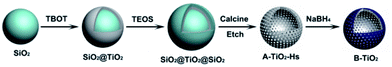
2.2 The preparation of mesoporous black TiO2 hollow spheres
Colloidal silica particles were prepared via a modified Stöber method.31 Briefly, 3.5 mL of TEOS was mixed with a solution of ethanol (90 mL), water (17.5 mL) and ammonia (2.5 mL) under vigorous magnetic stirring (700 rpm, WH220-HT) for 4 h. The formed colloidal silica particles were collected by centrifuging twice with ethanol and re-dispersed in 40 mL of ethanol under ultrasonication (500 W, JY92-2D). The coating of the silica particles with a TiO2 layer was conducted according to a previous report32 with minor modification. Briefly, the silica particles (10 mL) were mixed with 0.4 mL of water in 90 mL ethanol, and 0.4 g of HPC was added to the mixture under vigorous stirring. 30 min later, 4 mL of TBOT in 20 mL ethanol was added dropwise by the peristaltic pump within 40 min, followed by refluxing for 120 min at 90 °C under magnetic stirring. The particles were collected by centrifuging twice with ethanol and once with water. Subsequently, the particles were re-dispersed in 60 mL of water to give a SiO2@TiO2 suspension followed by adding 0.8 g of PVP and stirring overnight for the absorption of PVP on the surfaces of TiO2, which facilitated subsequent SiO2 coating on the TiO2 surfaces. The particles treated with PVP were washed once with water and twice with ethanol by way of centrifugation, and then re-dispersed in a solution of 100 mL of ethanol, 17.5 mL of water, 3.44 mL of TEOS and 2.5 mL of ammonia under vigorous stirring. Four hours later, the suspension was centrifuged three times, and the precipitates were re-dispersed in ethanol and dried at 70 °C. Finally, the precipitates were calcined at 800 °C for 4 h to crystallize the amorphous TiO2 to anatase TiO2 grains.
The crystalline SiO2@TiO2@SiO2 (0.5 g) particles obtained from the above calcination were dispersed in 150 mL of water, and then 1.0 g of NaOH was added to the suspension to etch the outermost and innermost SiO2 of the particles at 90 °C for 5 h. This produced well-defined mesoporous TiO2 hollow spheres that were collected by centrifuging 5 times with ethanol to wash out the residuals, and then dried at 70 °C.
The hollow TiO2 spheres were converted to black TiO2 using a modified NaBH4-reduction method.24,25 Briefly, 0.5 g of TiO2 hollow spheres were mixed with 0.5 g of NaBH4 (the ratio of TiO2 and NaBH4 was 1![[thin space (1/6-em)]](https://www.rsc.org/images/entities/char_2009.gif) :1) and ground thoroughly. The mixture was put into a porcelain boat and then transferred to a tube furnace (CHY-1200), then heat-treated at 320 °C, 350 °C, 380 °C and 400 °C under the protection of Ar atmosphere for 40 min (the samples thus obtained were named T320, T350, T380, and T400, respectively). After the samples were cooled naturally, the formed black TiO2 hollow spheres were collected and then washed twice with ethanol and three times with water. The final precipitates were re-dispersed in water, separated and then dried at −52 °C using a vacuum freeze dryer (FD-1A-50). About 12 h later, the powders were collected. The whole synthesis procedure is shown in Scheme 1.
:1) and ground thoroughly. The mixture was put into a porcelain boat and then transferred to a tube furnace (CHY-1200), then heat-treated at 320 °C, 350 °C, 380 °C and 400 °C under the protection of Ar atmosphere for 40 min (the samples thus obtained were named T320, T350, T380, and T400, respectively). After the samples were cooled naturally, the formed black TiO2 hollow spheres were collected and then washed twice with ethanol and three times with water. The final precipitates were re-dispersed in water, separated and then dried at −52 °C using a vacuum freeze dryer (FD-1A-50). About 12 h later, the powders were collected. The whole synthesis procedure is shown in Scheme 1.
 |
| | Scheme 1 Schematic of the formation of black TiO2 hollow spheres. | |
2.3 Characterization
The optical properties were detected by UV-Vis diffuse reflectance spectroscopy (UV-3600). The crystallinity was evaluated by X-ray diffraction (XRD) analysis (DX-2700, Dandong Fangyuan Corp., Liaoning, China). The morphology of the sample was characterized by transmission electron microscopy (TEM) (FEI Titan G2 60-300) and high-resolution transmission electron microscopy (HRTEM) (FEI Titan G2 60-300). X-ray photoelectron spectroscopy (XPS) (Thermo Fisher Scientific K-Alpha) was applied to analyze the valence state of the Ti element and the different binding states. Electron paramagnetic resonance (EPR) spectroscopy (Bruker E500) was employed to characterize the defects on the surfaces. An FL spectrophotometer (F-4600) was used to evaluate the concentration of ˙OH radicals using terephthalic acid photo-luminescence (TA-PL) with an excitation wavelength of 332 nm.
2.4 Photocatalytic degradation
The sample was used for the photocatalytic degradation of rhodamine B (RhB), for which a 300 W Xenon-lamp with a 400 nm cut-off filter was used as the visible light source. In a typical experiment, 30 mg of the sample was added to 250 mL of RhB aqueous solution (0.005 mM) and then dispersed under ultrasonication. A 60 min adsorption test under stirring in the dark was carried out to achieve an adsorption–desorption equilibrium before the visible light was turned on. Next, 4 mL of the suspension was sampled at a certain time interval and then filtered (1825-025) and centrifuged (8000 rpm for 2 min) for measuring the concentration of RhB using a UV 2000 spectrophotometer operating at 554.5 nm.
2.5 Photoelectrochemical experiments
Photocurrent measurements were done with a CHI 660E electrochemical workstation. The light source consisted of a 300 W Xe lamp with a cut off filter at 400 nm. Photocurrent measurements were performed with a CHI 660E electrochemical workstation. The light source consists of a 300 W Xe lamp with a cut off filter at 420 nm. The mixture was dip-coated onto a 1 cm × 2 cm FTO-glass to form a film as the working electrode. Pt foil, a saturated Hg/HgO electrode, and 0.5 M Na2SO3 were used as the counter electrode, reference electrode, and electrolyte, respectively. For electrochemical impedance spectroscopic (EIS) measurements, a three-electrode supercapacitor, composed of a Pt electrode and standard Hg/HgO reference electrode, was used; 3 M KOH was used as the electrolyte.
3. Results and discussion
3.1 The morphology of black hollow TiO2 photocatalysts
The morphology of the prepared samples was characterized by TEM. Fig. 1a–c shows the SiO2 spheres, TiO2-coated SiO2 spheres, and SiO2–TiO2-coated SiO2 spheres, respectively. The SiO2 spheres exhibit good monodispersibility and smooth surface, with a uniform size of ∼150 nm (Fig. 1a). Fig. 1b shows that the TiO2-coated SiO2 spheres have a rough surface with a diameter of about 250 nm, demonstrating the successful coating of TiO2 outer layers on SiO2 spheres. As shown in Fig. 1c, the surfaces of the particles became smooth again after coating the TiO2 layer with SiO2, and these particles were larger than the pure SiO2 particles in Fig. 1a. Thus, one can conclude that the SiO2@TiO2@SiO2 structure was formed for the particles and they had good mono-dispersity. Furthermore, the mono-disperse TiO2 hollow sphere (Fig. 1d) formed by etching using NaOH had a size of ∼250 nm, which is consistent with the previous report.32 The TEM image of a black TiO2 particle (T350) formed by the reduction of the TiO2 hollow spheres using NaBH4 is shown in Fig. 1e; the particle still maintained the hollow sphere morphology. The HRTEM image of the particle (Fig. 1f) shows that there is an amorphous layer on the surface of the hollow TiO2 particle (Fig. 1e), which could be attributed to the formation of black TiO2.1,15 In contrast, the internal section has high crystallinity with the lattice spacing of ∼0.35 nm, which coincides with the (101) spacing of the anatase phase.
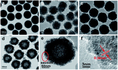 |
| | Fig. 1 TEM of SiO2 spheres (a), SiO2@TiO2 spheres (b), SiO2@TiO2@SiO2 spheres (c), TiO2 hollow spheres (d), T350 (e), and the HRTEM of T350 (f). | |
3.2 Structure and composition of hollow black TiO2 photocatalysts
The elemental distribution was characterized by TEM line scanning and map scanning. Fig. 2a shows a typical black TiO2 hollow sphere and Fig. 2b–d shows the distribution of Ti, Si and Na elements, respectively. According to the mapping density of each element, the major component is Ti, followed by Si. As shown in Fig. 2d, elemental Na is still present, which could be due to the NaOH for etching or NaBH4 for Ti4+-reduction. The arrows in Fig. 2f shows the line scanning direction and the corresponding element content were shown in Fig. 2e. The Si content was very low, thus the vast majority of the SiO2 was removed by etching using NaOH. The content of element B was also very low, making it negligible in the black TiO2 hollow spheres, which is consistent with previous works.24,25
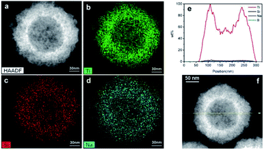 |
| | Fig. 2 The map scanning (a–d) and the line scanning (e and f) of the black TiO2 hollow sphere (T350). | |
3.3 The effect of mesoporous hollow structure and catalyst concentration on photocatalytic performance
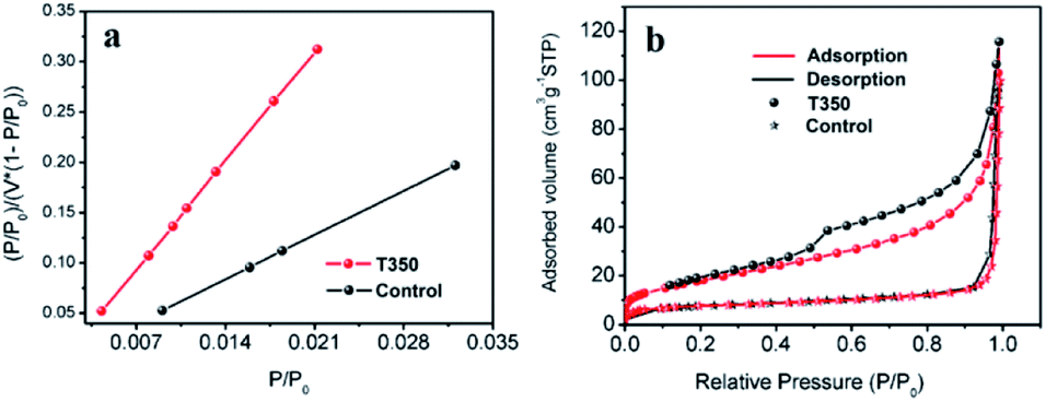
The effect of the specific surface area on the photocatalytic performance has been reported in many works.33,34 In our work, SiO2@black TiO2, the core–shell solid spheres, were chosen as the control group. The sample was obtained by reducing the SiO2@TiO2 spheres with NaBH4 at 350 °C, with the same reduction process as the black TiO2 hollow spheres (T350). The specific surface areas of the T350 and control samples were ∼66 m2 g−1 and ∼27 m2 g−1, respectively, similar to previous reports,33,34 as determined by the BET method (see Fig. 3a and Table S1†). The adsorption–desorption isotherm (Fig. 3b) was used to characterize the porosity of the samples. The formed hysteresis loop illustrates the richer pore structure on the surface of T350.34 Moreover, the distribution of the pores of the control sample and T350 are shown in Fig. S1.† There is a big difference between the control sample and T350 both in 2–10 nm and ∼120 nm, which means that a hierarchical porosity composed of mesopores (2–10 nm) connected with macropores (∼120 nm) was formed in the T350. Hierarchical porosity has been proven to favor multi-light scattering/reflection and facilitate fast mass transport, resulting in improved performance both in the enhanced harvesting of the exciting light and the improved photocatalytic activity.35,36 The large differences in specific surface area and pore structure make the hollow structure more suitable for photocatalysis because of more reaction sites and unique light absorption.
 |
| | Fig. 3 BET-adsorption-test results (a) and adsorption–desorption isotherms (b) of T350 and the control sample. | |
The visible-light-driven photocatalysis of the black TiO2 hollow spheres (T350) and the control sample with different catalyst concentrations was investigated. RhB, a well-known organic pollutant, was chosen to test the photocatalytic performance of the samples. As shown in Fig. 4a, the black TiO2 hollow spheres exhibited improved photocatalytic properties. The catalyst concentration has an obvious influence on the catalytic efficiency, i.e., catalytic efficiency increases as the catalyst concentration increases. When the catalyst content was increased to 0.28 mg mL−1, RhB was nearly fully catalyzed in 40 minutes, which is higher than the previous report.37 In contrast, the control group (0.28 mg mL−1) catalyzed only ∼50% in 90 minutes. The variation in the −ln(C/C0) versus the visible-light irradiation time is shown in Fig. 4b; it should be noted that the catalytic performance of T350 is ∼6 fold higher than that of the control group. The big difference in photocatalysis between the two cases can be ascribed to the hollow structure of the catalyst, as it can provide a larger specific surface area and more reactive sites.34
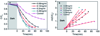 |
| | Fig. 4 Photocatalytic degradation of RhB under visible-light irradiation of T350 with different concentrations, and the control sample (a); variations of −ln(C/C0) versus visible-light irradiation time (b). | |
3.4 Structure and composition of hollow black TiO2 photocatalysts with different degrees of lattice disorder
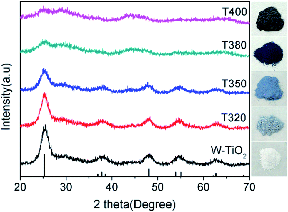
To further elucidate the photocatalytic mechanism, a series of black TiO2 hollow spheres were reduced with NaBH4 at different temperatures to engineer different degrees of lattice disorder in the shells of the samples. The samples thus derived were examined using XRD for their crystalline structures, as shown in Fig. 5. The standard card (JCPDS no. 21-1272) of anatase TiO2 was used as a reference. As seen from Fig. 5, the white titanium dioxide (W-TiO2) exhibits high crystallinity, and its XRD pattern is consistent with the anatase phase of TiO2.33 Furthermore, the crystallinity of the samples became lower as the reduction temperature increased. Their optical images (right side of Fig. 5) show that the initial sample (W-TiO2) was white, whereas, with increasing reduction temperature, the samples became light blue, blue, black and dark brown. The change in color is an indication of the formation of black TiO2, due to the increased degree of surface lattice disorder and the decrease in Ti valence from Ti4+ to Ti3+ after treatment with NaBH4;24 the blacker the TiO2, the lower the ratio of O/Ti and the greater the lower valence state amount, similar to the previous report.38 This change is consistent with the evolution of XRD patterns in Fig. 5.
 |
| | Fig. 5 The XRD patterns of different samples and corresponding optical images. | |
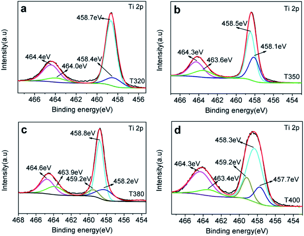
XPS was used to detect the surface chemical binding of the powders reduced at different temperatures. The elements Ti, O, C and Si appeared in the full-scale XPS spectra, as shown in Fig. S2.† The appearance of C is due to the carbonation of organic molecules on the particle surfaces in heat treatment. Furthermore, the XPS peaks of Ti 2p in T320 can be fitted with four peaks centered at 458.4 eV, 458.7 eV, 464.0 eV, and 464.4 eV, and those in T350 with peaks centered at 458.1 eV, 458.5 eV, 463.6 eV, and 464.3 eV. These correspond to the binding energies of Ti3+ 2p3/2, Ti4+ 2p3/2, Ti3+ 2p1/2, and Ti4+ 2p1/2, respectively. Ti3+ emerged due to the effect of hydrogen reduction induced by the thermal decomposition of NaBH4.24,25 Besides, the ratios of Ti3+ to Ti4+ were about 32.5% (T320) and 51.4% (T350), as shown in Table 1, which were higher than most of the reports.24,39,40 Similarly, as shown in Fig. 6c and d, the peak of the T380 can fit to five peaks centered at 458.8 eV, 458.2 eV, 459.2 eV, 463.9 eV and 464.6 eV, and 458.3 eV, 457.7 eV, 459.2 eV, 463.4 eV and 464.3 eV in T400. The peaks centered at 458.8 eV (458.3 eV in T400), 458.2 eV (457.7 eV in T400), 463.9 eV (463.4 eV in T400), and 464.6 eV (464.3 eV in T400) correspond to the Ti4+ 2p3/2, Ti3+ 2p3/2, Ti3+ 2p1/2, and Ti4+ 2p1/2 respectively, and the peak centered at 459.2 eV belongs to Ti2+.41 It should be noted that Ti3+ emerges when the reduction temperature is 320 °C, as shown in Fig. 4a. The amount of Ti3+ increased when the reduction temperature increased to 350 °C. Ti2+ first appeared in the sample when the temperature increased further to 380 °C, and its content increased further when the reduction temperature was increased to 400 °C.24 The emergence of Ti3+ and Ti2+ can be due to the reduction of Ti4+, which could lead to the formation of oxygen vacancies. It indicated that the number of surface defects increased with increasing reduction temperature, as also suggested by the XRD data shown in Fig. 5, and by EPR data. The valence band (VB) XPS spectra of T350 and W-TiO2 are shown in Fig. S5.†
Table 1 Details of Ti 2p of the samples
| Valence |
Sample |
| T320 |
T350 |
T380 |
T400 |
| Ti4+ |
75.5% |
66% |
62.2% |
70.8% |
| Ti3+ |
24.50% |
34% |
27.3% |
14.3% |
| Ti2+ |
— |
— |
10.5% |
14.9% |
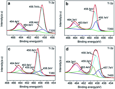 |
| | Fig. 6 Ti 2p XPS spectra for (a) T320, (b) T350, (c) T380 and (d) T400. | |
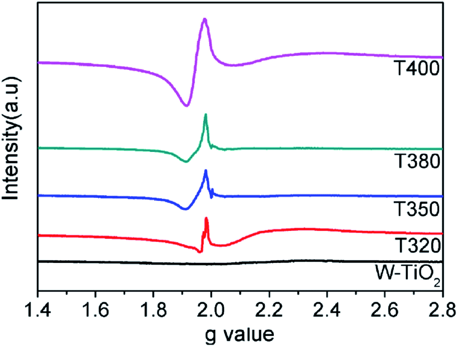
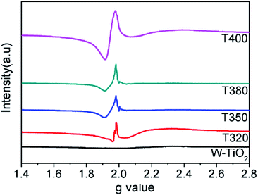
EPR spectra were adopted to detect unpaired spins and magnetism on the surface of the sample, specifically the existence of Ti3+ ions and oxygen vacancies. As shown in Fig. 7, compared with the W-TiO2, the peaks centered at g = 1.945 emerged in the reduced samples. The intensities of these peaks increased as the reduction temperature increased, denoting that there were more defects formed on the surfaces. Theoretically, the peaks centered at g = 1.945 originated from the paramagnetic Ti3+ state, and the peaks at g = 2.002 in T350 and T380 correspond to unpaired electrons trapped by oxygen vacancies;42 both peaks are relevant to the photocatalysis. In T320 and T400, the signal from g = 2.002 is absent, which means that the peak at g = 1.945 can be composed of Ti3+ and some lower valence states, such as Ti2+,24 also seen in other materials.43 No EPR signal was detected in W-TiO2, indicating that the surface defects on black TiO2 particles were produced when the samples were treated with NaBH4, which corresponds to other reports.24,25
 |
| | Fig. 7 EPR spectra of the W-TiO2, T320, T350, T380 and T400. | |
3.5 Optical properties of hollow black TiO2 photocatalysts
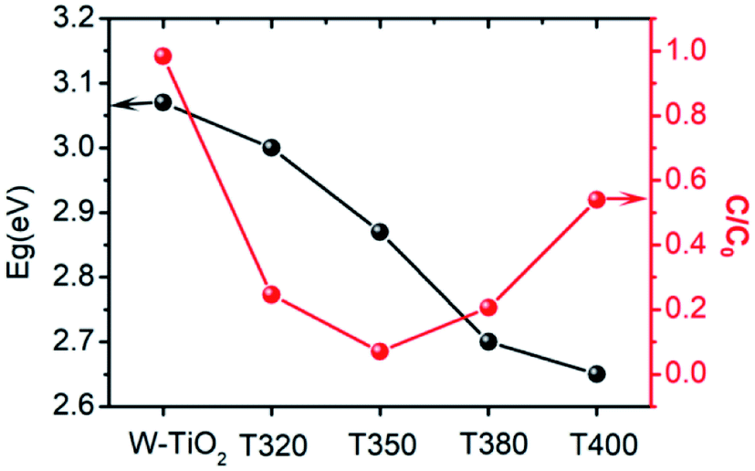
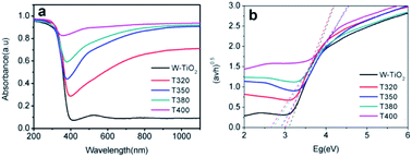
The photo-absorption properties of the samples were characterized by UV-Vis, as shown in Fig. 8a. W-TiO2 possesses high absorption under ultraviolet irradiation, but weak absorption in visible light. In contrast, the reduced samples (T320, T350, T380, and T400) exhibited obvious absorption in visible light, and the intensity of the absorption increased as the reduction temperature gradually increased. The incredible changes in optical properties can be attributed to the treatment with NaBH4, which can produce Ti3+ and oxygen vacancies, similar to previous work.24 The values of the bandgap were also calculated according to the previous report44 and the corresponding results are shown in Fig. 8b. The as-prepared W-TiO2 has a bandgap of 3.07 eV, and the band gap values of T320, T350, T380 and T400 are 3.0 eV, 2.87 eV, 2.7 eV and 2.65 eV, respectively. It is commonly regarded that black TiO2 exhibits decreased band gap and improved visible-light absorption, which leads to enhanced and efficient visible light catalysis.17 We tried to verify this assertion using our photocatalytic experiments as described below.
 |
| | Fig. 8 The UV-Vis absorption (a), and the corresponding value of band gap (b) of the samples. | |
3.6 Visible-light-driven catalytic activity and electrochemical properties
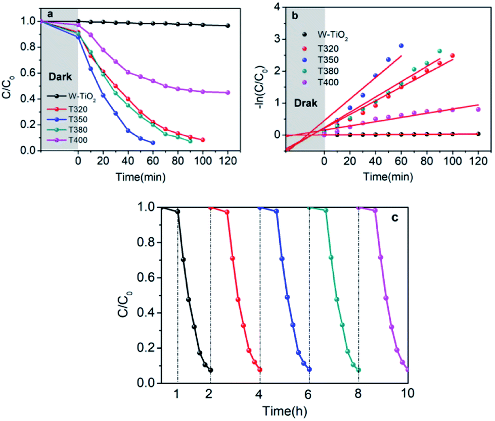
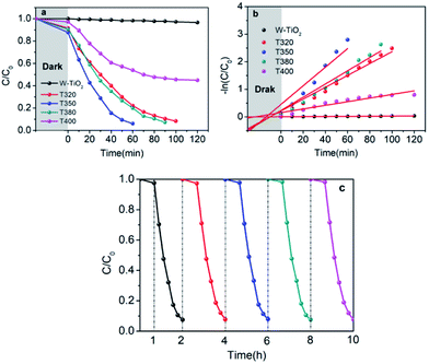
It can be seen from Fig. 9 that the samples obtained by reduction with NaBH4 at different temperatures have different visible-light photocatalytic effects. W-TiO2 was used as a control sample. As shown in Fig. 9a, using T320, T350, T380 and T400 as the photo-catalysts, the quantity of RhB was reduced by 75.5%, 93.1%, 79.6% and 46.2%, respectively, with a reaction time of 1 h. The variation of the −ln(C/C0) versus the visible-light irradiation time is shown in Fig. 9b, which suggests the degradation reaction is a first-order reaction. It is noted that the catalytic performance of T350 is ∼5 fold higher than that of T400, ∼1.4 fold that of T380 and ∼2 times that of T320. The cycling tests revealed that the T350 was very stable in five photocatalysis cycles shown in Fig. 9c. Generally, the higher visible light degradation performances in black TiO2 can attribute to the relatively high concentrations of defects and the smaller band gaps in the black TiO2 samples.18 As shown in Fig. 10, the values of the band gap decrease regularly with the reduction temperature. This tendency is consistent with that of the visible-light absorption properties. However, the catalytic efficiency is not proportional to the band gap, as observed in previous works.24 This demonstrates a contradiction between the visible-light degradation performance and band gap in black TiO2.
 |
| | Fig. 9 Photocatalytic degradation of RhB under visible-light irradiation (a), variations of −ln(C/C0) versus visible-light irradiation time (b) with a catalyst concentration of 0.12 mg mL−1. (c) Cycling tests of the visible-light-driven photocatalytic activity of T350. | |
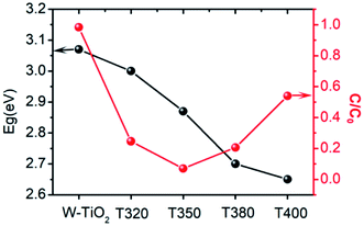 |
| | Fig. 10 The change in band gap (black line) and catalytic efficiency in 1 h (red line) for different samples. | |
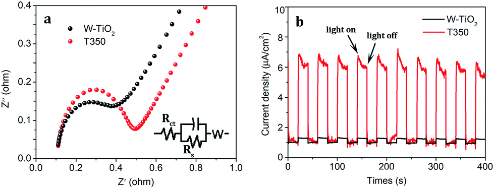
Moreover, the EIS of the obtained samples is also characterized as shown in Fig. 11a. T350 has the smaller circular arc radius and the larger slope, which means that it has a higher separation efficiency of photoexcited electron–hole pairs than W-TiO2.37 The transient photocurrent responses of W-TiO2 and T350 are shown in Fig. 11b. The photocurrent response of T350 is about 5 times that of W-TiO2, which is consistent with the above properties, suggesting that photoexcited electron–hole pairs are highly separated.35,45,46 So the appearance of surface defects is considered to be the real factor that mainly affects photocatalysis.
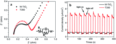 |
| | Fig. 11 The (a) electrochemical impedance spectra and (b) photocurrent responses for W-TiO2 and T350. | |
3.7 Theoretical analysis and photocatalytic mechanism
According to the above description, we tried to identify the factors that predominantly determine the photocatalysis reaction. As shown in Fig. S3,† the concentration of surface OH species in T350 is lower than that in other samples. Nonetheless, it has the highest photocatalytic performance. Thus, surface OH species are not a determining factor. As shown in Fig. 8 and 9, the photocatalytic ability of a black TiO2 is not directly proportional to the visible light absorption (or the bandgap). Hence, the photo-absorption and band gap are also non-critical to the photocatalytic properties. As shown in Fig. 5, the amount of surface defects increases with the heat-treatment temperature,24 which would enhance the photocatalytic ability. However, the photocatalytic ability of black TiO2 is not proportional to the intensity of EPR either. The type of surface defects may also influence the photocatalysis by black TiO2. As shown in the XPS of Ti 2p (Fig. 4), the intensities of Ti3+ peaks increase from W-TiO2 (Fig. S4a†) to T350, but decrease from T350 to T400, whereas the Ti2+ species appear in T380 and its intensity increases with reduction temperature in T400. On correlating these facts with the photo-catalytic data in Fig. 7, we infer that Ti3+ plays a critical role in the catalysis when Ti3+ is present as in T320 and T350. However, when Ti2+ appears, such as in T380 and T400, it offsets the positive effect of Ti3+ and restrains the photocatalysis; thus, the relative concentrations of Ti3+ and Ti2+ species predominantly determine the catalytic capability of the black TiO2 under study.
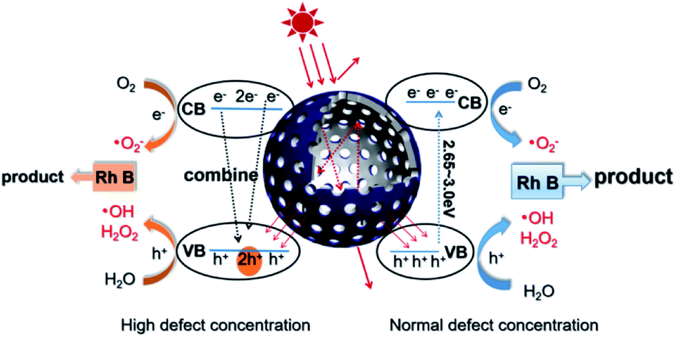
Based on the above discussions, a visible-light-driven photocatalytic mechanism can be proposed as shown in Scheme 2. The light pathways are shown in the particle. The efficiency of light utilization is greatly increased due to the multiple refractions of the hollow black TiO2 structure when compared to a solid sphere. The high specific surface area of the hollow spheres can provide more reaction sites, which also contributes to the enhanced photocatalysis.33,34
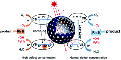 |
| | Scheme 2 Schematic of the visible-light-driven photocatalytic mechanism and the light pathway in the hollow structure. | |
With a normal defect concentration as in the T320 or T350 samples, the photon-excited electrons (e−) are transferred from the VB to the CB when the photons (hv > Eg) hit the surface of the sample, leaving holes (h+) in the VB and the formed electrons (e−) in the CB.47 The photon generated electrons (e−) can react with the oxygen dissolved in a solution to produce superoxide anion radicals (˙O2−), while the absorbed water can be oxidized by the holes (h+) to form hydroxide anions (˙OH) and hydrogen peroxide (H2O2) (see Fig. S6†). Both radicals (˙O2− and ˙OH) can participate in the degradation of organic pollutants. The relevant reactions are shown below.34,48
With a high defect concentration as in the T380 or T400 samples, the defects can also act as charge recombination centers, as shown in Scheme 2. The excited electrons (e−) will fall back to the VB, which will decrease the photocatalytic ability of the sample. As stated above, we think defects associated with Ti2+ play the role of charge recombination centers,49 so the emergence of Ti2+ is harmful to photocatalysis. The formation process of Ti2+ is shown in Fig. S7.†
4. Conclusions
In this work, black TiO2 with mesoporous hollow shell structures were synthesized using the EISA method integrated with etching by NaOH and reduction by NaBH4. The unique structured black TiO2 exhibited significantly improved visible-light-driven photocatalytic properties, due to higher specific surface area, more reaction sites, and enhanced visible light absorption capability. Moreover, the black TiO2 hollow spheres with different lattice disorder-engineering degrees were designed by reducing the samples at 320 °C, 350 °C, 380 °C and 400 °C, respectively. It was found that the higher the reduction temperature, the greater the disorder in the black TiO2 samples, accompanied by higher visible light absorption. However, the photocatalytic efficiency changed with the processing temperature non-monotonically: it increased first and then decreased. This phenomenon can be explained by the varied functions of the surface defects at different concentrations in the black TiO2 during the catalytic process. Our work provides significant insight into the mechanism accounting for the high efficiency in the visible-light-driven catalysis by hollow black TiO2 spheres, which may guide the development of new applications for the newly fabricated black TiO2 materials.
Conflicts of interest
There are no conflicts to declare.
Acknowledgements
This work was financially supported by the National Natural Science Foundation of China (No. 11404226 and 61771327), NSFC (No. U1730138), Science and Technology Project of Sichuan Province (No. 2018GZ0328) and the Fundamental Research Funds for Central Universities.
Notes and references
- X. B. Chen, L. Liu, Y. Y. Peter and S. S. Mao, Science, 2011, 311, 746–750 CrossRef.
- W. Zhou, W. Li, J. Q. Wang, Y. Qu, Y. Yang, Y. Xie, K. F. Zhang, L. Wang, H. G. Fu and D. Y. Zhao, J. Am. Chem. Soc., 2014, 136, 9280–9283 CrossRef CAS.
- T. H. Zhou, W. Lv, J. Li, G. G. Zhou, Y. Zhao, S. X. Fan, B. L. Liu, B. H. Li, F. Y. Kang and Q. H. Yang, Energy Environ. Sci., 2017, 10, 1694–1703 RSC.
- H. Zhang, X. J. Lv, Y. M. Li, Y. Wang and J. H. Li, ACS Nano, 2010, 4, 380–386 CrossRef CAS PubMed.
- S. G. Ullattil and P. Periyat, J. Mater. Chem. A, 2016, 4, 5854 RSC.
- S. Banerjee, D. D. Dionysiou and S. C. Pillai, Appl. Catal., B, 2015, 176–177, 396–428 CrossRef CAS.
- B. M. Kale, J. Wiener, J. Militky, S. Rwawiire, R. Mishra, K. I. Jacob and Y. J. Wang, Carbohydr. Polym., 2016, 150, 107–113 CrossRef CAS.
- B. H. Wu, D. Y. Liu, S. Mubeen, T. T. Chuong, M. Moskovits and G. D. Stucky, J. Am. Chem. Soc., 2016, 138, 1114–1117 CrossRef CAS PubMed.
- A. Sinhamahapatra, H. Y. Lee, S. H. Shen, S. S. Mao and J. S. Yu, Appl. Catal., B, 2018, 237, 613–621 CrossRef CAS.
- J. Warnan, J. Willkomm, Y. Farré, Y. Pellegrin, M. Boujtita, F. Odobel and E. Reisner, Chem. Sci., 2019, 10, 2758 RSC.
- E. Sundin and M. Abrahamsson, Chem. Commun., 2018, 54, 5289 RSC.
- X. B. Chen and C. Burda, J. Am. Chem. Soc., 2008, 130, 5018–5019 CrossRef CAS.
- Y. F. Xu, C. Zhang, L. X. Zhang, X. H. Zhang, H. L. Yao and J. L. Shi, Energy Environ. Sci., 2016, 9, 2410 RSC.
- Z. W. Seh, S. H. Liu, M. Low, S. Y. Zhang, Z. L. Liu, A. Mlayah and M. Y. Han, Adv. Mater., 2012, 24, 2310–2314 CrossRef CAS.
- T. Q. Lin, C. G. Yang, Z. Wang, H. Yin, X. J. Lü, F. Q. Huang, J. H. Lin, X. M. Xie and M. H. Jiang, Energy Environ. Sci., 2014, 7, 967 RSC.
- Y. Fang, M. G. Sun, Y. Wang, S. F. Sun and J. He, Mater. Res. Bull., 2016, 74, 265–270 CrossRef CAS.
- Z. Wang, C. Y. Yang, T. Q. Lin, H. Yin, F. Q. Huang, J. H. Lin, X. M. Xie and M. H. Jiang, Energy Environ. Sci., 2013, 6, 3007 RSC.
- Z. Wang, C. Y. Yang, T. Q. Lin, H. Yin, P. Chen, D. Y. Wan, F. F. Xu, F. Q. Huang, X. M. Xie and M. H. Jiang, Adv. Funct. Mater., 2013, 23, 5444–5450 CrossRef CAS.
- Y. Yan, M. Han, A. Konkin, T. Koppe, D. Wang, T. Andreu, G. Chen, U. Vetter, J. R. Morante and P. Schaaf, J. Mater. Chem. A, 2014, 2, 12708 RSC.
- J. Dong, J. Han, Y. Liu, A. Nakajima, S. Matsushita, S. Wei and W. Gao, ACS Appl. Mater. Interfaces, 2014, 6, 1385 CrossRef CAS.
- H. Li, Z. Chen, C. K. Tsang, Z. Li, X. Ran, C. Lee and B. Pan, J. Mater. Chem. A, 2014, 2, 229 RSC.
- M. W. Shah, Y. Zhu, X. Fan, J. Zhao, Y. Li, S. Asim and C. Wang, Sci. Rep., 2015, 5, 15084 CrossRef.
- G. Shu, H. Wang, H. X. Zhao and X. J. Zhang, ACS Appl. Mater. Interfaces, 2019, 11, 3323–3333 CrossRef CAS.
- H. Q. Tan, Z. Zhao, M. Niu, C. Y. Mao, D. P. Cao, D. J. Cheng, P. Y. Feng and Z. C. Sun, Nanoscale, 2014, 6, 10216 RSC.
- Y. Cao, Z. P. Xin, Y. C. Shen, Z. Z. Li, X. Y. Wu, X. Yan, J. L. Zou, S. L. Yan and W. Zhou, Chem. Eng. J., 2017, 325, 199–207 CrossRef CAS.
- Y. Zhang, Z. P. Xing, X. F. Liu, M. Li, Q. Zhu and W. Zhou, ACS Appl. Mater. Interfaces, 2016, 8, 26851–26859 CrossRef CAS.
- W. J. Xu, Y. C. Bai and Y. D. Yin, Adv. Mater., 2018, 30, 1802091 CrossRef.
- W. Zhang, H. He, Y. Tian, K. Lan, Q. Liu, C. Y. Wang, Y. Liu, A. Elzatahry, R. C. Che, W. Li and D. Y. Zhao, Chem. Sci., 2019, 10, 1664 RSC.
- X. Wang, L. C. Bai, H. Y. Liu, X. F. Yu, Y. D. Yin and C. B. Gao, Adv. Funct. Mater., 2017, 1704208 Search PubMed.
- N. Liu, X. M. Zhou, N. T. Nguyen, K. Peters, F. Zoller, I. Hwang and P. Schmuki, ChemSusChem, 2017, 10, 62–67 CrossRef CAS.
- W. Stöber, A. Fink and E. Bohn, J. Colloid Interface Sci., 1968, 26, 62 CrossRef.
- J. B. Joo, Q. Zhang, M. Dahl, I. Lee, J. Goebl, F. Zaera and Y. D. Yin, Energy Environ. Sci., 2012, 5, 6321 RSC.
- Ji. B. Joo, I. Lee, M. Dahl, G. D. Moon, F. Zaera and Y. D. Yin, Adv. Funct. Mater., 2013, 23, 4246–4254 CrossRef CAS.
- H. Y. Liu, H. Ma, J. B. Joo and Y. D. Yin, Sci. China Mater., 2016, 59(12), 1017–1026 CrossRef CAS.
- B. Z. Fang, A. Bonakdarpour, K. Reilly, Y. L. Xing, F. Taghipour and D. P. Wilkinson, ACS Appl. Mater. Interfaces, 2014, 6, 15488–15498 CrossRef CAS.
- B. Z. Fang, J. H. Kim, M. S. Kim and J. S. Yu, Acc. Chem. Res., 2013, 46, 1397–1406 CrossRef CAS.
- Y. Cao, Z. P. Xing, M. Q. Hu, Z. Z. Li, X. Y. Wu, T. Y. Zhao, Z. Y. Xiu, S. L. Yan and W. Zhou, J. Catal., 2017, 356, 246–254 CrossRef CAS.
- M. M. Ye, J. Jia, Z. J. Wu, C. X. Qian, R. Chen, P. G. O'Brien, W. Sun, Y. C. Dong and G. Ozin, Adv. Energy Mater., 2017, 7, 1601811 CrossRef.
- H. L. Cui, W. Zhao, C. Y. Yang, H. Yin, T. Q. Lin, H. Gua and F. Q. Huang, J. Mater. Chem. A, 2014, 2, 8612 RSC.
- X. Chen, D. X. Zhao, K. W. Liu, C. R. Wang, Z. Z. Zhang and D. Z. Shen, ACS Appl. Mater. Interfaces, 2015, 7, 16070–16077 CrossRef CAS.
- T. Hanawa, J. Periodontal Implant Sci., 2011, 41, 263–272 CrossRef CAS.
- C. P. Kumar, N. O. Gopal, T. C. Wang, M. S. Wong and S. C. Ke, J. Phys. Chem. B, 2006, 110, 5223–5229 CrossRef CAS.
- Y. Su, J. Lang, L. Li, K. Guan, C. Du, L. Peng, D. Han and X. J. Wang, J. Am. Chem. Soc., 2013, 135, 11433–11436 CrossRef CAS.
- B. Roose, S. Pathak and U. Steiner, Chem. Soc. Rev., 2015, 44, 8326–8349 RSC.
- W. Zhong, S. Shen, M. He, D. Wang, Z. Wang, Z. Lin and J. Yu, Appl. Catal., B, 2019, 258, 117967 CrossRef CAS.
- W. Zhong, Z. Lin, S. Feng, D. Wang, S. Shen, Q. Zhang and B. Fang, Nanoscale, 2019, 11(10), 4407–4413 RSC.
- X. B. Chen, C. Li, M. Grätzel, R. Kosteckid and S. S. Mao, Chem. Soc. Rev., 2012, 41, 7909–7937 RSC.
- Y. Nosaka and A. Y. Nosaka, Chem. Rev., 2017, 117, 11302–11336 CrossRef CAS.
- R. Su, R. Tiruvalam, Q. He, N. Dimitratos, L. Kesavan, C. Hammond, G. J. Hutchings and F. Besenbacher, ACS Nano, 2012, 6, 6284–6292 CrossRef CAS.
Footnote |
| † Electronic supplementary information (ESI) available: Detail of XPS, VB XPS, specific surface area and fluorescence spectroscopy. See DOI: 10.1039/c9ra08148h |
|
| This journal is © The Royal Society of Chemistry 2019 |
Click here to see how this site uses Cookies. View our privacy policy here. 
 Open Access Article
 This Open Access Article is licensed under a
  b,
Junzheng Gaoa,
Wanxia Huang*a,
Qiwu Shi
b,
Junzheng Gaoa,
Wanxia Huang*a,
Qiwu Shi