 Open Access Article
Synthesis and characterisation of fluorinated epitaxial films of BaFeO2F: tailoring magnetic anisotropy via a lowering of tetragonal distortion†
Akash Nair a,
Stephan Wollstadta,
Ralf Witteb,
Supratik Dasguptac,
Philipp Kehnec,
Lambert Alff
 c,
Philipp Komissinskiy
 *c and
Oliver Clemens
 *ab
*ab
aTechnische Universität Darmstadt, Institute of Materials Science, Materials Design by Synthesis Division, Alarich-Weiss-Straße 2, 64287 Darmstadt, Germany. E-mail: oliver.clemens@md.tu-darmstadt.de; Fax: +49 6151 16 21991
bKarlsruhe Institute of Technology, Institute of Nanotechnology, Hermann-von-Helmholtz-Platz 1, 76344 Eggenstein Leopoldshafen, Germany
cTechnische Universität Darmstadt, Institute of Materials Science, Advanced Thin Film Technology Division, Alarich-Weiss-Straße 2, 64287 Darmstadt, Germany. E-mail: komissinskiy@oxide.tu-darmstadt.de; Fax: +49 6151 16 20699
First published on 13th November 2019
Abstract
In this article, we report on the synthesis and characterisation of fluorinated epitaxial films of BaFeO2F via low-temperature fluorination of thin films of BaFeO2.5+d grown by pulsed laser deposition. Diffraction measurements show that fluoride incorporation only results in a contraction of the film perpendicular to the film surface, where clamping by the substrate is prohibitive for strong in-plane changes. The fluorinated films were found to be homogenous regarding the fluorine content over the whole film thickness, and can be considered as single crystal equivalents to the bulk phase BaFeO2F. Surprisingly, fluorination resulted in the change of the tetragonal distortion to a nearly cubic symmetry, which results in a lowering of anisotropic orientation of the magnetic moments of the antiferromagnetically ordered compound, confirmed by Mössbauer spectroscopy and magnetic studies.
1 Introduction
Perovskite-type and perovskite-related transition metal oxides with stoichiometric ABO3, A2BO4, A3B2O7 and non-stoichiometric ABO3−x compositions, (where A: rare earth or alkali earth ion, and B: 3d, 4d, or 5d transition metal ion) can exhibit fascinating physical and chemical properties, including multiferroicity,1–3 high temperature superconductivity,4 colossal magnetoresistance,5 and photocatalytic activity.6One of the most interesting aspects of these oxides is the ability to engineer/tune their physical properties by tailoring the composition of the cation sites (i.e. the 12-fold coordinated A- and/or the 6-fold coordinated B-site) and/or partially replacing the oxygen by other anionic species such as hydride,7,8 fluoride,9–12 or nitride13 ions. This most often originates from a tuning of the electronic structure and coordination chemistry of the constituent species. One of the methods that has been used to incorporate fluoride ions to change oxidation states of transition metals within perovskite type (or perovskite related) materials are low-temperature topochemical fluorination routes.9–11,14,15
The necessity for using low temperature topotactic fluorination routes originates from the fact that the majority of oxyfluoride perovskites are only metastable and will decompose at elevated temperature to form alkaline earth fluorides or lanthanide oxyfluorides. Therefore, for most of these compounds it is not possible to grow single crystals at elevated temperatures. Within the last years, adopted approaches have been reported for fluoride incorporation into epitaxially grown thin films.14–19 This does not only provide the opportunity to investigate such films as a grain boundary free model system to study bulk related properties, but also to use strain engineering20 to further modify materials' properties.
Bulk BaFeO2.5 (BFO) crystallizes in a complex vacancy ordered modification of the cubic perovskite type structure.21–23 This monoclinic modification is centrosymmetric with space group P21/c. This compound can be fluorinated using polymer-based routes, and BaFeO2.33F0.33 (vacancy ordered, P21/m)24,25 and BaFeO2F (BFOF) (no significant amounts of vacancies, cubic, Pm![[3 with combining macron]](https://www.rsc.org/images/entities/char_0033_0304.gif) m) can be formed depending on the amount of polymer used.26–28 As is common for perovskites with trivalent iron mainly, these compounds show G-type antiferromagnetic ordering with Néel temperatures above 500 K.
m) can be formed depending on the amount of polymer used.26–28 As is common for perovskites with trivalent iron mainly, these compounds show G-type antiferromagnetic ordering with Néel temperatures above 500 K.
Although the structure of BFOF appears simple at first glance, the local structure around the iron seems to deviate significantly from having perfect octahedral symmetry. Heap et al.27,28 were the first to notice an unusual high atomic displacement parameter of the Fe3+ cations, and different configurations of fluoride ions within the FeO4F2 octahedra (cis = both fluoride ions at the same edge; trans = fluoride ions located at opposite corners) were discussed in the context of the compound lacking long-range anion ordering. In combination with Mössbauer spectroscopic studies, a non-centrosymmetric cis environment around a majority of Fe cations from mainly statistic distribution of fluoride ions was concluded.28
The fact that there seems to be chance given for the absence of centrosymmetry around the Fe3+ cations makes the compound of principle interest for possessing multiferroic properties. To approach such applications, an additional understanding of the structure within fluorinated epitaxially grown thin films seems to be appreciable.
Here, we report two different approaches to topochemical fluorination of epitaxially grown BFO thin films on single crystalline (001) oriented substrates of SrTiO3.29,30 We show that the films can be chemically fluorinated via different approaches under formation of BFOF without significant substrate fluorination. Via a combination of structural analysis, Mössbauer spectroscopy as well as magnetic studies, an improved understanding of the structural and magnetic behaviour of the films could be gained.
2 Experimental
2.1 Growth of BFO thin films
The BFO target was prepared using a conventional solid state synthesis route. Stoichiometric ratios of solid BaCO3 (Alfa Aesar, >99.8%) and Fe2O3 (Sigma-Aldrich, >99%) were ground, uniaxially pressed and heated twice to 1100 °C for 24 h under flowing Ar with intermediate regrinding.BFO thin films with a thickness of ∼85 nm were grown on (001)-oriented SrTiO3 (STO) substrates via pulsed laser deposition (PLD) in the custom made ultra-high vacuum PLD system which is a part of the Darmstadt Integrated System for Battery Research (DaISy-Bat). The BFO target was ablated with a KrF excimer laser (λ = 248 nm) at a repetition rate of 1 Hz and at a fluence of 1.4 J cm−2. During deposition, the substrates were heated up to a temperature of 700 °C from their back side, using a high power near infrared diode laser at 938 nm. A background oxygen pressure of 0.018 mbar was used for all depositions. After deposition, the films were cooled down to room temperature at a rate of 50 K min−1. These conditions were chosen in accordance with previous experiments within our group.29,30
2.2 Thin film fluorination
Two fluorination approaches were attempted to fluorinate thin films of BFO to BFOF, which did not show strong differences with respect to the quality, structure and composition of the films reported within this article. In the first approach14 (see Fig. 1), a solution of 10 wt% of poly-(vinylidene difluoride) (PVDF) in acetone is ‘dropped’ onto an as-grown oxygen deficient BFO film. This method will be referred to as “drop fluorination” in the following. The film was then heated in air for 24 h at 375 °C.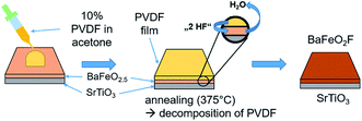 | ||
| Fig. 1 Representation of drop-fluorination method as carried out on BFO films. The figure is recreated and related to the scheme shown in ref. 14. | ||
In a second approach14 (see Fig. 2), a PVDF powder is placed in a tube furnace heated to 240 °C in front of a BFO film with respect to the gas flow direction. Decomposition products of PVDF, such as HF or small chain components, are then carried over the film and fluorinate it. This approach will be referred to as “vapour transport” fluorination in the following. For this process, a large excess of ∼2 g of dry PVDF were used (the estimated amount of polymer necessary for full fluorination of the film is in the order of 1–5 μg).
 | ||
| Fig. 2 Vapour transport process carried out on as-grown oxygen deficient BFO placed downstream from PVDF pellets in a heated alumina tube in the presence of a flowing carrier gas. The figure is recreated and related to the scheme shown in ref. 14. | ||
Within this reaction, the fluorine from the decomposition of PVDF under formation of HF can be expected to occupy the interstitial vacancies and replace oxygen from the lattice equally in the film according to
| OO + Vi + 2HF → FO + Fi + H2O | (1) |
2.3 Structural characterisation
The X-ray diffraction (XRD) θ–2θ measurement of the BFO target was performed using a Bruker D8 Advance diffractometer in Bragg–Brentano geometry showing phase purity of the target material as reported previously.29 The thin-film XRD θ–2θ measurements were performed in parallel beam geometry using a Cu-Kα1 Rigaku SmartLab X-ray diffractometer with a Ge(220) 2-bounce monochromator.2.4 X-ray photoelectron spectroscopy (XPS)
X-ray photoelectron spectroscopy (XPS) measurements were performed within the DAISY-BAT system with a PHI Versaprobe 5000 spectrometer equipped with a monochromated Al Kα X-ray source at 1486.6 eV. All the measurements were carried out at room temperature at a pass energy of 23.5 eV and an energy step size of 0.1 eV. The as-grown BFO films were transferred into the XPS chamber under UHV conditions (<10−8 Torr) and, therefore, were not exposed to ambient atmosphere prior to the XPS measurements. For fluorinated films, adsorbates such as carbon could not be avoided on the surface of the films as the fluorination reaction was performed outside the UHV system. To probe the inward homogenous incorporation of fluoride into the films, XPS depth profile analysis was performed via argon ion sputtering at an accelerating voltage of 4 kV and an ion current of 3 μA. The adventitious carbon contaminations were detected at the surface of the film only before Ar ion sputtering. Following the first sputtering cycle, no carbon peak could be detected.2.5 SQUID magnetometry
Magnetic properties of the samples were measured as a function of the applied magnetic field and temperature using a magnetic property measurement system (MPMS) by Quantum Design, equipped with a superconducting quantum interference device (SQUID). The magnetization data were corrected for diamagnetic contributions from the SrTiO3 substrate. Two different sets of measurements were performed on the same films in non-fluorinated and fluorinated states. Magnetization M for each film was measured as a function of the applied magnetic field H between −2 T and 2 T at 10 K. Magnetization versus temperature curves were recorded between 298 and 10 K at H = 200 Oe in a field cooled (FC) and zero field cooled (ZFC) regimes.2.6 Conversion electron Mössbauer spectroscopy (CEMS)
Conversion Electron Mössbauer Spectroscopy (CEMS) was measured with a 57Co in Rh matrix source (∼50 mCi) and the velocity was varied with a constant acceleration drive. The conversion electrons from the resonant absorption of gamma-rays were detected with a custom-built gas-proportional counter, with a mixture of CH4 (4%) in He as detector gas. The velocity scale was calibrated with a bcc Fe standard and all isomer shifts are given relative to bcc Fe at room temperature.3 Results and discussion
3.1 Structural analysis
In agreement with our previous findings,29,30 the XRD measurements showed that the BFO film can be grown in a pseudo-cubic phase (see black curves in Fig. 3a and b). The extracted out-of-plane lattice parameter c = 4.13 Å of the BFO film differs strongly from the lattice parameter of the STO substrate (a = 3.905 Å). The inset in Fig. 3b shows a rocking curve measurement, showing a full-width at half-maximum (FWHM) of 0.05° for the (002) BFO reflection. The narrow FWHM indicates a high degree of crystallinity and low mosaicity throughout the depth of the film. The value of the lattice parameter c = 4.13 Å lies between the values of 4.11 Å observed by Benes et al.29 for 200 nm thick films and of 4.15 Å reported by Sukkurji et al.30 for 20–30 nm thick films. This indicates that the tetragonal distortion due to the epitaxial strain depends on the film thickness.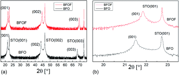 | ||
| Fig. 3 (a) High resolution X-ray diffractograms of an as-deposited BFO (black) and fluorinated BFOF (red) film on SrTiO3 substrates (b) expanded view of the (001) BFO and BFOF reflections. | ||
After fluorination, the BFOF films do not show any significant change in orientation or strong relaxations within the film, as no additional reflections are observed in the XRD patterns. However, strong shifts of the film (00l) XRD reflections are observed independent of the fluorination method used (see red curves in Fig. 3a and b as well as Fig. S1†), which implies a small BFOF lattice parameter c ≈ 4.066 Å. Remarkably, this value is similar to what has been reported for the bulk phase of BFOF by Heap et al.27 (a = 4.058 Å).
For the BFOF film, the slightly larger FWHM = 0.08° has been extracted from the rocking curve of the (002) reflection (see Fig. S2†) than for the BFO film (FWHM = 0.05°), which indicates a small additional broadening after fluorine incorporation. This indicates a small increase of mosaicity after the topochemical incorporation of fluoride ions.
X-ray reciprocal space mapping (RSM) was carried out to determine the in-plane lattice parameter and to understand the topochemical fluorination of the film in better detail. For this purpose, mapping around the STO (103) reflection of the BFO and BFOF films was performed, as shown in Fig. 4a and b.
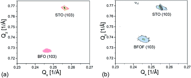 | ||
| Fig. 4 X-ray reciprocal space mapping of the (a) BFO and (b) drop-fluorinated BFOF films measured around the (103) STO reflection. | ||
The shift in the film peak of the BFO film (Fig. 4a) along Qx in comparison with the shift of the peak of STO substrate indicates that the lattice mismatch is too high for the growth of a fully strained film. This observation is in agreement with our previous study30 which showed the presence of dislocations at the film/substrate interface. The in-plane and out-of-plane lattice parameters of a = 4.065 and c = 4.128 Å, respectively, were calculated from the RSM measurements (see Table 1).
| Film | ain-plane | cout-of-plane |
|---|---|---|
| BFO | 4.065(5) Å | 4.128(6) Å |
| BFOF | 4.066(3) Å | 4.066(4) Å |
| STO | 3.902 Å | 3.903 Å |
After fluorination, the BFOF film stays fully strained on the SrTiO3 substrate and the Qx position of the (103) BFOF film reflection is not changed (see Fig. 4b). This fact gives a strong support for the topotactic nature of the fluorination, which does not break clamping of the film to the substrate and allows only relaxation of the film perpendicular to the substrate plane. Meanwhile, significant changes of the RSM pattern of the BFOF are found along Qz, implying a strong decrease of the c value to approximately 4.066 Å (Table 1). Thus, it is remarkable that the film fluorination indeed results in basically cubic cell metrics, with an average lattice parameter being close to what is found for powders of BaFeO2F (a = 4.058 Å (ref. 27 and 28)). Therefore, (taking into account the results of the compositional analysis presented below in Section 3.2), the BFOF films can be considered as being a close approximation to a single crystal of this metastable phase, which cannot be obtained by classic techniques of crystal growth.
3.2 Compositional analysis
Fig. 5 shows a depth profile of the normalized elemental concentration in the BFOF film as extracted from the XPS measurements. In agreement with previous findings,14,16,19,30 fluorine is only observed throughout the complete thickness of the BFOF film. No fluorine is detected in the SrTiO3 substrate within the resolution limit of about 0.1 at% of the XPS system. This is well plausible as PVDF does not have sufficient reductive power to form low-valent Ti species.31 The detected sudden emergence of the Sr 3d and Ti 2p peaks indicates a sharp interface between the film and the substrate with no sign of interdiffusion of the metal species into the BFOF film. Note that in the interface region denoted with the vertical black lines, the elemental concentration is imprecise and not given. Within the BFOF film, a rather homogenous distribution of the elements Ba, Fe, O, and F could be confirmed. The Ba![[thin space (1/6-em)]](https://www.rsc.org/images/entities/char_2009.gif) :
:![[thin space (1/6-em)]](https://www.rsc.org/images/entities/char_2009.gif) Fe ratio of ∼1
Fe ratio of ∼1![[thin space (1/6-em)]](https://www.rsc.org/images/entities/char_2009.gif) :
:![[thin space (1/6-em)]](https://www.rsc.org/images/entities/char_2009.gif) 1 in combination with a O
1 in combination with a O![[thin space (1/6-em)]](https://www.rsc.org/images/entities/char_2009.gif) :
:![[thin space (1/6-em)]](https://www.rsc.org/images/entities/char_2009.gif) F ratio of ∼2
F ratio of ∼2![[thin space (1/6-em)]](https://www.rsc.org/images/entities/char_2009.gif) :
:![[thin space (1/6-em)]](https://www.rsc.org/images/entities/char_2009.gif) 1 indicates the composition of BaFeO2F, indicating a fully fluorinated state of the sample, in agreement with the Mössbauer spectra which indicate the presence of Fe3+ only (see Section 3.3). Deviations from the ideal composition are within the reliability of the method and should be interpreted neither as anion rich films (i.e., lower oxidation states, as ruled out from Mössbauer spectroscopy, see Section 3.3), nor the presence of, e.g. Ruddlesden–Popper related, Ba2FeO4 type defects (not indicated within the XRD analysis, see previous section). We would also like to emphasize that a very similar compositional behaviour is indicated the formation of BaFeO2F films via the second fluorination method (see Fig. S3†). Thus, a BaFeO2.33F0.33 (ref. 24 and 25) phase with intermediate fluorine concentration and ordered anion vacancies could not be synthesized with these methods. This phase is either unstable in the investigated strained BFOF films on the SrTiO3 substrates or requires precise control of the fluorine concentration in the film at the level of about 1 μg (only few μg of fluorine are necessary for a full fluorination of the film), which has not been achieved in the presented fluorination methods.
1 indicates the composition of BaFeO2F, indicating a fully fluorinated state of the sample, in agreement with the Mössbauer spectra which indicate the presence of Fe3+ only (see Section 3.3). Deviations from the ideal composition are within the reliability of the method and should be interpreted neither as anion rich films (i.e., lower oxidation states, as ruled out from Mössbauer spectroscopy, see Section 3.3), nor the presence of, e.g. Ruddlesden–Popper related, Ba2FeO4 type defects (not indicated within the XRD analysis, see previous section). We would also like to emphasize that a very similar compositional behaviour is indicated the formation of BaFeO2F films via the second fluorination method (see Fig. S3†). Thus, a BaFeO2.33F0.33 (ref. 24 and 25) phase with intermediate fluorine concentration and ordered anion vacancies could not be synthesized with these methods. This phase is either unstable in the investigated strained BFOF films on the SrTiO3 substrates or requires precise control of the fluorine concentration in the film at the level of about 1 μg (only few μg of fluorine are necessary for a full fluorination of the film), which has not been achieved in the presented fluorination methods.
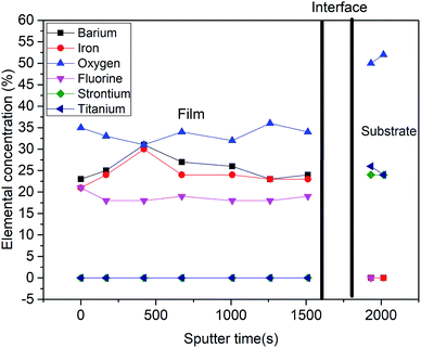 | ||
| Fig. 5 Normalized concentration–depth profile for a BFOF film corresponding to all the elements observed in XPS spectra. | ||
3.3 57Fe mössbauer spectroscopy
57Fe conversion electron Mössbauer spectra were recorded for the BFO and drop-fluorinated BFOF films at 298 K (see Fig. 6a and b). It should be noted that the signals from the films were quite weak, which can be explained by the low thickness (∼85 nm) of the films. Although the signal-to-noise ratio is low, certain conclusions can still be drawn from the measurements.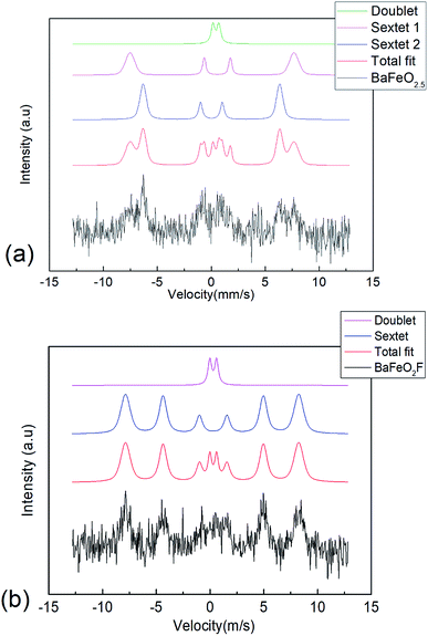 | ||
| Fig. 6 57Fe conversion electron Mössbauer spectrum recorded from (a) BFO and (b) BFOF at room temperature. | ||
(1) The spectrum observed for BFO is similar to our previous study of 200 nm thick films.29 It can be fitted with a similar distribution of sextets as reported for bulk BaFeO2.5 (ref. 23) (see Table 2 and Fig. 6a), which agrees with tetrahedrally (low isomer shift, sextet 2), square pyramidally, and octahedrally (high isomer shift, sextet 1 & doublet) coordinated iron species within this film. The fit shows that although no long-range ordering of anion vacancies can be obtained within a strained film, the overall distribution of coordination polyhedra must be considered to be similar to the bulk state.29
| Sextet 1 (pink, 40%) | Sextet 2 (blue, 48%) | Doublet (green, 12%) | |
|---|---|---|---|
| Isomer shift (IS) | 0.43(4) mm s−1 | 0.12(3) mm s−1 | 0.54(5) mm s−1 |
| Quadrupole splitting (QS) | −0.49(7) mm s−1 | 0 mm s−1 (fixed) | 0.54(8) mm s−1 |
| Hyperfine field | 47.2(4) T | 39.3(2) T | |
| Lorentzian width | 0.30(11) mm s−1 | 0.39(13) mm s−1 | 0.4 mm s−1 (fixed) |
| Gaussian width | 2.3(4) | 1.2(4) | — |
(2) On fluorination of the film to BFOF, the complexity of the spectrum strongly reduces. The spectrum can then be basically fitted with one sextet and one doublet (see Table 3 and Fig. 6b). All isomer shifts are indicative for iron being present in its trivalent oxidation state, in agreement with a composition following BaFe+IIIO2+xF1−2x (x ∼ 0). Further, the isomer shift observed for the main sextet is indicative for octahedral environments, where the reduction compared to the octahedrally coordinated FeO6 species in BaFeO2.5 indicates the presence of the fluoride ions within the coordination environment, and therefore well agrees with the formation of FeO4F2 octahedra.32
| Sextet (blue, 88%) | Doublet (pink, 12%) | |
|---|---|---|
| Isomer shift (IS) | 0.35(2) mm s−1 | 0.40(3) mm s−1 |
| Quadrupole splitting (QS) | −0.10(4) mm s−1 | 0.62(6) mm s−1 |
| Hyperfine field | 50.0(2) T | |
| Lorentzian width | 0.66(11) mm s−1 | 0.4 mm s−1 (fixed) |
| Gaussian line width | 1.7(4) | — |
(3) The presence of mainly sextet species clearly evidences magnetic ordering of films. In this respect, we observed that the intensity ratio of the individual sextet lines changed from the non-fluorinated BFO film to the fluorinated BFOF film. For BFO, magnetic anisotropy was already observed in our previous study,29 which is indicated by a change of the relative intensities of the signals of the sextets. Namely a strong decrease of the second and fifth line, which shows a alignment of the magnetic moments parallel to the gamma ray, hence in out-of-plane direction of the thin films along the c-axis of the lattice. After fluorination, the BFOF film shows a more isotropic orientation of the magnetic moments indicated by the altered relative intensities of the Mössbauer lines of the sextets towards what would be expected for a randomly oriented powder (intensity ratio of first to second to third line 4![[thin space (1/6-em)]](https://www.rsc.org/images/entities/char_2009.gif) :
:![[thin space (1/6-em)]](https://www.rsc.org/images/entities/char_2009.gif) 3
3![[thin space (1/6-em)]](https://www.rsc.org/images/entities/char_2009.gif) :
:![[thin space (1/6-em)]](https://www.rsc.org/images/entities/char_2009.gif) 1). This agrees with the absence of significant straining after fluorination and a cubic symmetry of the film and is in agreement with literature reports for bulk BaFeO2F.28 The doublet species are commonly found for the various modifications of BaFeO2F32 and most likely are related to magnetically disordered regions within the films. Furthermore, the values of the observed hyperfine field splittings are high and agree with the presence of magnetically ordered high-spin Fe3+ at temperatures well below the magnetic ordering temperature.33
1). This agrees with the absence of significant straining after fluorination and a cubic symmetry of the film and is in agreement with literature reports for bulk BaFeO2F.28 The doublet species are commonly found for the various modifications of BaFeO2F32 and most likely are related to magnetically disordered regions within the films. Furthermore, the values of the observed hyperfine field splittings are high and agree with the presence of magnetically ordered high-spin Fe3+ at temperatures well below the magnetic ordering temperature.33
(4) For bulk BaFeO2F, a random distribution of fluoride ions, forming cis (two fluoride ions at the same edge of the octahedron) and trans (two fluoride ions at opposite corners of the octahedron) was considered as the most plausible structural scenario.28 It is difficult to determine whether more than one sextet signal is present within the BFOF film. The fact that the sextet is considerably broadened by a Gaussian distribution (width of 1.7 T) might indicate that the different crystallographic scenarios cannot be resolved and are thus compiled in the broad sextet. However, the small quadrupole splitting of the sextet species might indicate a nearly centrosymmetric environment, which is only the case for the trans configuration of anions within FeO4F2 octahedra.
3.4 Magnetic analysis
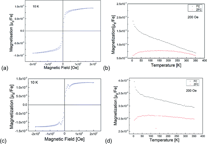
Fig. 7 shows the results of the magnetization measurements of the BFO and BFOF films. For both films, the measured saturation magnetic moments are below 0.015 μB per Fe at 10 K in agreement with usually observed antiferromagnetically ordered Fe3+-containing perovskites.23,27,28,32,34–37 A small difference between the FC and ZFC measurements is similar to the previously reported data for bulk BaFeO2.5 (ref. 23) and BaFeO2F.28 In agreement with previous discussions with respect to the magnetic hyperfine field splittings observed via Mössbauer spectroscopy,28 these results indicate a canted antiferromagnetic ordering of Fe3+ ions in both BFO and BFOF films with a small canting angle below 0.1°. Overall, no difference could be observed for the magnetic behaviour of the non-fluorinated BFO and the fluorinated BFOF films. Their similar low magnetic moments at low temperatures and curvature of the magnetization temperature dependence indicate that no significant change in the Fe3+ antiferromagnetic ordering occurs after fluorination. Thus, we cannot draw conclusions on potential changes of the Néel temperature, which is known to depend on the fluorine content (e.g. decreasing of the Néel temperatures from 750 K for LaFeO3 to 645 K for BaFeO2F, and even further to ∼480 K for AgFeOF2).384 Conclusions
In this work we have shown that polymer based routes are efficient means in order to prepare chemically homogenous epitaxial thin films of BaFeO2F via the low temperature topochemical fluorination of thin films of BaFeO2.5 grown by PLD. No significant differences in film quality were found for the investigated drop-fluorination and vapour transport fluorination methods. The incorporation of fluorine results in a change of the tetragonal distortion to a cubic symmetry, which lowers the magnetic anisotropy of the film of the antiferromagnetically ordered moments. In addition, a small degree of ferromagnetic canting could be observed, similar to what is found for bulk barium ferrates.28In future works, our group will also focus on the preparation of strained films of BaFeO2F by using substrates which could allow for more strict cube-on-cube growth, which could then result in additional decrease of symmetry, targeting to form novel multiferroic compounds.
Conflicts of interest
The authors declare no conflicts of interest.Acknowledgements
This work was funded by the German Research Foundation, DFG, within CL551/2-1, and the Open Access Publishing Fund of Technische Universität Darmstadt.References
- G. Catalan and J. F. Scott, Physics and Applications of Bismuth Ferrite BiFeO3, Adv. Mater., 2009, 21(24), 2463 CrossRef CAS.
- X. Cheng, X. Wang, H. Yang, K. Ruan and X. Li, Multiferroic properties of the layered perovskite-related oxide La6(Ti0.67Fe0.33)6O20, J. Mater. Chem. C, 2015, 3(17), 4482 RSC.
- J. Ma, J. Hu, Z. Li and C. W. Nan, Recent progress in multiferroic magnetoelectric composites: from bulk to thin films, Adv. Mater., 2011, 23(9), 1062 CrossRef CAS PubMed.
- C. N. R. Rao, Perovskite oxides and high-temperature superconductivity, Ferroelectrics, 1990, 102(1), 297 CrossRef CAS.
- B. Raveau, A. Maignan, C. Martin and M. Hervieu, Colossal Magnetoresistance Manganite Perovskites: Relations between Crystal Chemistry and Properties, Chem. Mater., 1998, 10(10), 2641 CrossRef CAS.
- M. Imada, A. Fujimori and Y. Tokura, Metal-insulator transitions, Rev. Mod. Phys., 1998, 70(4), 1039 CrossRef CAS.
- M. A. Hayward and M. J. Rosseinsky, Cool conditions for mobile ions, Nature, 2007, 450, 960 CrossRef CAS PubMed.
- T. Yajima, A. Kitada, Y. Kobayashi, T. Sakaguchi, G. Bouilly, S. Kasahara, T. Terashima, M. Takano and H. Kageyama, Epitaxial thin films of ATiO(3-x)H(x) (A = Ba, Sr, Ca) with metallic conductivity, J. Am. Chem. Soc., 2012, 134(21), 8782 CrossRef CAS PubMed.
- O. Clemens and P. R. Slater, Topochemical modifications of mixed metal oxide compounds by low-temperature fluorination routes, Rev. Inorg. Chem., 2013, 33(2–3), 105 CAS.
- C. Greaves and M. G. Francesconi, Fluorine insertion in inorganic materials, Curr. Opin. Solid State Mater. Sci., 1998, 3(2), 132 CrossRef CAS.
- E. E. McCabe and C. Greaves, Review: Fluorine insertion reactions into pre-formed metal oxides, J. Fluorine Chem., 2007, 128, 448 CrossRef CAS.
- K. Wissel, J. Heldt, P. B. Groszewicz, S. Dasgupta, H. Breitzke, M. Donzelli, A. I. Waidha, A. D. Fortes, J. Rohrer and P. R. Slater, et al., Topochemical Fluorination of La2NiO4+d: Unprecedented Ordering of Oxide and Fluoride Ions in La2NiO3F2, Inorg. Chem., 2018, 57(11), 6549 CrossRef CAS PubMed.
- S. Yoon, K. Son, S. G. Ebbinghaus, M. Widenmeyer and A. Weidenkaff, Ferromagnetism in nitrogen and fluorine substituted BaTiO3, J. Alloys Compd., 2018, 749, 628 CrossRef CAS.
- E. J. Moon, A. K. Choquette, A. Huon, S. Z. Kulesa, D. Barbash and S. J. May, Comparison of topotactic fluorination methods for complex oxide films, APL Mater., 2015, 3(6), 062511 CrossRef.
- T. Katayama, A. Chikamatsu, Y. Hirose, R. Takagi, H. Kamisaka, T. Fukumura and T. Hasegawa, Topotactic fluorination of strontium iron oxide thin films using polyvinylidene fluoride, J. Mater. Chem. C, 2014, 2(27), 5350 RSC.
- E. J. Moon, Y. Xie, E. D. Laird, D. J. Keavney, C. Y. Li and S. J. May, Fluorination of Epitaxial Oxides: Synthesis of Perovskite Oxyfluoride Thin Films, J. Am. Chem. Soc., 2014, 136(6), 2224 CrossRef CAS PubMed.
- K. Kawahara, A. Chikamatsu, T. Katayama, T. Onozuka, D. Ogawa, K. Morikawa, E. Ikenaga, Y. Hirose, I. Harayama and D. Sekiba, et al., Topotactic fluorination of perovskite strontium ruthenate thin films using polyvinylidene fluoride, CrystEngComm, 2017, 19(2), 313 RSC.
- P. A. Sukkurji, A. Molinari, C. Reitz, R. Witte, C. Kuebel, V. S. K. Chakravadhanula, R. Kruk and O. Clemens, Anion Doping of Ferromagnetic Thin Films of La0.74Sr0.26MnO3-delta via Topochemical Fluorination, Materials, 2018, 11(7), 1204 CrossRef PubMed.
- A. Chikamatsu, Y. Suzuki, T. Maruyama, T. Onozuka, T. Katayama, D. Ogawa and T. Hasegawa, Selective fluorination of perovskite iron oxide/ruthenium oxide heterostructures via a topotactic reaction, Chem. Commun., 2019, 55(17), 2437 RSC.
- O. Copie, J. Varignon, H. Rotella, G. Steciuk, P. Boullay, A. Pautrat, A. David, B. Mercey, P. Ghosez and W. Prellier, Chemical Strain Engineering of Magnetism in Oxide Thin Films, Adv. Mater., 2017, 29(22), 1604112 CrossRef PubMed.
- M. Parras, M. Vallet-Regi, J. M. Gonzalez-Calbet, M. A. Alario-Franco, J. C. Grenier and P. Hagenmuller, A reassessment of Ba2Fe2O5, Mater. Res. Bull., 1987, 22(10), 1413 CrossRef CAS.
- X. D. Zou, S. Hovmoller, M. Parras, J. M. Gonzalez-Calbet, M. Vallet-Regi and J. C. Grenier, The complex perovskite-related superstructure Ba2Fe2O5 solved by HREM and CIP, Acta Crystallogr., Sect. A: Found. Crystallogr., 1993, A49(1), 27 CrossRef CAS.
- O. Clemens, M. Groeting, R. Witte, J. Manuel Perez-Mato, C. Loho, F. J. Berry, R. Kruk, K. S. Knight, A. J. Wright and H. Hahn, et al., Crystallographic and Magnetic Structure of the Perovskite-Type Compound BaFeO2.5: Unrivaled Complexity in Oxygen Vacancy Ordering, Inorg. Chem., 2014, 53(12), 5911 CrossRef CAS PubMed.
- O. Clemens, Structural characterization of a new vacancy ordered perovskite modification found for Ba3Fe3O7F (BaFeO2.333F0.333): Towards understanding of vacancy ordering for different perovskite-type ferrites, J. Solid State Chem., 2015, 225, 261 CrossRef CAS.
- O. Clemens, C. Reitz, R. Witte, R. Kruk and R. I. Smith, Anion ordering, magnetic structure and properties of the vacancy ordered perovskite Ba3Fe3O7F, J. Solid State Chem., 2016, 243, 31 CrossRef CAS.
- O. Clemens, R. Haberkorn, P. R. Slater and H. P. Beck, Synthesis and characterisation of the SrxBa1-xFeO3-y-system and the fluorinated phases SrxBa1-xFeO2F, Solid State Sci., 2010, 12(8), 1455 CrossRef CAS.
- R. Heap, P. R. Slater, F. J. Berry, O. Helgason and A. J. Wright, Synthesis and structural determination of the new oxide fluoride BaFeO2F, Solid State Commun., 2007, 141, 467 CrossRef CAS.
- F. J. Berry, F. C. Coomer, C. Hancock, Ö. Helgason, E. A. Moore, P. R. Slater, A. J. Wright and M. F. Thomas, Structure and magnetic properties of the cubic oxide fluoride BaFeO2F, J. Solid State Chem., 2011, 184(6), 1361 CrossRef CAS.
- A. Benes, A. Molinari, R. Witte, R. Kruk, J. Broetz, R. Chellali, H. Hahn and O. Clemens, Proton Conduction in Grain-Boundary-Free Oxygen-Deficient BaFeO2.5+delta Thin Films, Materials, 2018, 11(1), 52 CrossRef PubMed.
- P. A. Sukkurji, A. Molinari, A. Benes, C. Loho, V. S. K. Chakravadhanula, S. K. Garlapati, R. Kruk and O. Clemens, Structure and conductivity of epitaxial thin films of barium ferrite and its hydrated form BaFeO2.5-x+delta(OH)2x, J. Phys. D: Appl. Phys., 2017, 50(11), 115302 CrossRef.
- K. Wissel, S. Dasgupta, A. Benes, R. Schoch, M. Bauer, R. Witte, A. D. Fortes, E. Erdem, J. Rohrer and O. Clemens, Developing intercalation based anode materials for fluoride-ion batteries: topochemical reduction of Sr2TiO3F2 via a hydride based defluorination process, J. Mater. Chem. A, 2018, 6(44), 22013 RSC.
- O. Clemens, J. F. Marco, M. F. Thomas, S. D. Forder, H. Zhang, S. Cartenet, A. Monze, P. A. Bingham, P. R. Slater and F. J. Berry, Magnetic interactions in cubic-, hexagonal- and trigonal-barium iron oxide fluoride, BaFeO2F, J. Phys.: Condens. Matter, 2016, 28(34), 346001 CrossRef PubMed.
- M. Parras, L. Fournes, J. C. Grenier, M. Pouchard, M. Vallet, J. M. Calbet and P. Hagenmuller, Structural aspects and Mössbauer resonance investigation of Ba2Fe2O5, J. Solid State Chem., 1990, 88(1), 261 CrossRef CAS.
- F. J. Berry, R. Heap, Ö. Helgason, E. A. Moore, S. Shim, P. R. Slater and M. F. Thomas, Magnetic order in perovskite-related SrFeO2F, J. Phys.: Condens. Matter, 2008, 20(21), 215207 CrossRef.
- O. Clemens, F. J. Berry, J. Bauer, A. J. Wright, K. S. Knight and P. R. Slater, Synthesis, structural and magnetic characterisation of the fluorinated compound 15R-BaFeO2F, J. Solid State Chem., 2013, 203, 218 CrossRef CAS.
- O. Clemens, F. J. Berry, A. J. Wright, K. S. Knight, J. M. Perez-Mato, J. M. Igartua and P. R. Slater, A neutron diffraction study and mode analysis of compounds of the system La1-xSrxFeO3-xFx (x=1, 0.8, 0.5, 0.2) and an investigation of their magnetic properties, J. Solid State Chem., 2013, 206, 158 CrossRef CAS.
- O. Clemens, A. J. Wright, F. J. Berry, R. I. Smith and P. R. Slater, Synthesis, structural and magnetic characterisation of the fully fluorinated compound 6H-BaFeO2F, J. Solid State Chem., 2013, 198, 262 CrossRef CAS.
- F. Takeiri, T. Yamamoto, N. Hayashi, S. Hosokawa, K. Arai, J. Kikkawa, K. Ikeda, T. Honda, T. Otomo and C. Tassel, et al., AgFeOF2: A Fluorine-Rich Perovskite Oxyfluoride, Inorg. Chem., 2018, 57(11), 6686 CrossRef CAS PubMed.
Footnote |
| † Electronic supplementary information (ESI) available. See DOI: 10.1039/c9ra08039b |
| This journal is © The Royal Society of Chemistry 2019 |

