 Open Access Article
Electrospun acellular scaffolds for mimicking the natural anisotropy of the extracellular matrix†
Samerender Nagam Hanumantharao ,
Nastaran Alinezhadbalalami,
Srinivas Kannan,
Meghan Friske and
Smitha Rao
 *
*
Department of Biomedical Engineering, Michigan Technological University, Houghton, MI 49931, USA. E-mail: smithar@mtu.edu
First published on 16th December 2019
Abstract
In tissue engineering, the use of scaffolds helps establish a synergistic relationship between the scaffolds and the tissues by improving cell–scaffold interaction. This interaction is enhanced when physiologically relevant biophysical cues are replicated in the artificial scaffolds. Here, we present a novel scaffold that mimics the natural anisotropy of the native extracellular matrix of tissues, fabricated by electrospinning a combination of three polymers: polycaprolactone (PCL), polyvinylidene fluoride (PVDF) and polyaniline (PANI). The scaffolds were characterized for their morphology, surface and mechanical properties. Rat cardiomyoblast (H9c2) cells, cultured on the PCL–PANI–PVDF scaffold, demonstrated cell alignment, penetration and proliferation across the entire surface area of the scaffold without any external chemical or physical stimuli. The PCL–PANI–PVDF scaffold, unlike other scaffolds, does not require post-processing or specific temperature conditions of storage, prior to use. These acellular scaffolds fabricated through polymer blending, open new avenues for research on functional acellular scaffolds for tissue engineering, based on synthetic materials.
Introduction
Scaffold-based tissue engineering is an important strategy in current regenerative research and reconstructive surgery.1 Artificial matrices and scaffolds can emulate the natural microenvironment of cells and influence cell migration, differentiation, proliferation and survival for ex vivo cellular studies.2–4 However, in order to ensure appropriate cellular differentiation and proliferation, external stimulation or addition of growth factors is often required.5 For example, for connective tissues like the bone, the cells on the scaffolds are subjected to external stimuli such as constant compressive stress or axial stretching, to recreate the natural physical microenvironment.6,7 However, these external stimuli are ineffective in in vivo systems which must be minimalistic in design and reduce dependence on external factors. Modifying the material properties and surface morphology of a scaffold is one way of making the scaffold design simple, efficient and functional.8,9 In most synthetic scaffold-based processes, additional post-processing steps are required to make the scaffolds biocompatible and mechanically stable.10 These additional steps are time consuming and may further alter the physical structure and morphology of the scaffolds compromising their mechanical integrity.11 Such properties are of vital importance since the cell–scaffold interaction is dependent on several factors including the surface properties, morphology of the scaffold and its mechanical properties.12 Functional scaffolds made from polyblend nanofibers fabricated by electrospinning are one of the strategies to address this challenge.13 The polyblend nanofibers are a combination of one or more polymers in a ratio that allows them to be electrospun into scaffolds using coaxial electrospinning.14 This technique allows the scaffold to take advantage of some of the native characteristics of the individual polymers, while gaining some new functionality.15To achieve optimal cell–scaffold interaction, the surface and mechanical properties need to closely match with native tissues.16 The work presented here reports the fabrication of a 3D aligned nanofibrous scaffold, which closely replicates the mechanical anisotropy of the tissue and promotes cell proliferation without any external stimulation. Polycaprolactone (PCL), polyvinylidene fluoride (PVDF) and polyaniline (PANI) were used for the fabrication of the scaffold by coaxial electrospinning. The materials used were biocompatible, non-immunogenic and durable. PCL, a viscoelastic, aliphatic, biodegradable polyester is soluble in a number of organic solvents and compatible with many polymers which makes it an ideal candidate for blending with other polymers.17 PVDF is a piezoelectric and a mechanically strong polymer and PANI is a conductive polymer in the acidic state.18–20 A polymer scaffold composed of the three polymers provides the required flexibility in designing acellular scaffolds which mimic the surface and morphological properties of the natural extracellular matrix. Here, we developed a method to electrospin three distinct polymers by sequentially dissolving them in solvents with different boiling points and then coaxially electrospinning them to obtain a scaffold. The scaffold had an overall homogeneity composed of highly repetitive anisotropies analogous to native tissue. This unique morphology promotes cell adhesion, proliferation and migration in 3D without need for any growth factors, external stimuli and post processing.
Materials and methods
Fabrication of scaffolds
All the chemicals were used as procured unless specified. Polycaprolactone (Mw = 70![[thin space (1/6-em)]](https://www.rsc.org/images/entities/char_2009.gif) 000 GPC; Scientific Polymer Products, USA), PVDF (Mw = 534
000 GPC; Scientific Polymer Products, USA), PVDF (Mw = 534![[thin space (1/6-em)]](https://www.rsc.org/images/entities/char_2009.gif) 000; Sigma Aldrich; France) and PANI (emeraldine base; avg Mw ∼ 50
000; Sigma Aldrich; France) and PANI (emeraldine base; avg Mw ∼ 50![[thin space (1/6-em)]](https://www.rsc.org/images/entities/char_2009.gif) 000; Aldrich Chemistry, USA) were used for synthesis of the scaffolds including PCL and PCL–PVDF. The doped form of PANI–PCL solution was prepared by dissolving equal mass of emeraldine base and 10-camphorsulfonic acid (HCSA) (Aldrich Chemistry; France) in a solution of 10% PCL in chloroform. The PCL–PANI solution was filtered to remove suspensions larger than 0.22 μm since the doped form of PANI is immiscible.21 DMF (Macron Fine Chemicals; USA) and acetone (Sigma Aldrich, USA) in the ratio 7
000; Aldrich Chemistry, USA) were used for synthesis of the scaffolds including PCL and PCL–PVDF. The doped form of PANI–PCL solution was prepared by dissolving equal mass of emeraldine base and 10-camphorsulfonic acid (HCSA) (Aldrich Chemistry; France) in a solution of 10% PCL in chloroform. The PCL–PANI solution was filtered to remove suspensions larger than 0.22 μm since the doped form of PANI is immiscible.21 DMF (Macron Fine Chemicals; USA) and acetone (Sigma Aldrich, USA) in the ratio 7![[thin space (1/6-em)]](https://www.rsc.org/images/entities/char_2009.gif) :
:![[thin space (1/6-em)]](https://www.rsc.org/images/entities/char_2009.gif) 3 were used to prepare a 20% PVDF solution. PCL–PANI–PVDF scaffold was prepared by coaxially electrospinning from separate syringes which were controlled using syringe pumps (Harvard Pumps, EP-H11). The PCL–PANI (core solution) and 20% PVDF (sheath solution) were electrospun (EM-DIG; IME Technologies, Netherlands) at 18 kV using a rotating collector at a rotational speed of 750 rpm. The parameters used for fabrication of PCL and PCL–PVDF scaffolds are elaborated in the ESI.†
3 were used to prepare a 20% PVDF solution. PCL–PANI–PVDF scaffold was prepared by coaxially electrospinning from separate syringes which were controlled using syringe pumps (Harvard Pumps, EP-H11). The PCL–PANI (core solution) and 20% PVDF (sheath solution) were electrospun (EM-DIG; IME Technologies, Netherlands) at 18 kV using a rotating collector at a rotational speed of 750 rpm. The parameters used for fabrication of PCL and PCL–PVDF scaffolds are elaborated in the ESI.†
Characterization of scaffolds
The fiber samples were sputter coated with Au/Pd (5 nm thick) and visualized using a Field Emission Scanning Electron Microscope (Hitachi S-4700 FE-SEM) and a high-resolution transmission electron microscope (JEOL JEM-2010 TEM; HRTEM). The alignment of the fibers and average diameter were calculated from the images obtained using the directionality tool in the ImageJ software. Attenuated total reflectance (ATR) Fourier transform infrared (FTIR) spectroscopy (PerkinElmer FTIR-ATR 100 series) was collected in the range of 400–4000 cm−1 to study the surface chemistry. X-Ray Diffraction (XRD) was used to analyse the scaffolds using XDS 2000 Diffractometer (Scintag XDS-2000 Powder) and a Cu-Kα (λ = 1.54 Å) source of X-ray radiation. The X-ray spectra were analysed using the DMSNT software and the inbuilt Pearson VII profile fitting function. The mechanical properties of the scaffolds were analysed (n = 3) using a dynamic mechanical analyser (TA Instruments Q800 DMA).Cell culture
Rat cardiomyoblast cells were purchased from ATCC (H9c2; CRL-1446™), and cultured in Dulbecco's Modified Eagle's Medium, DMEM (Life Technologies, USA) supplemented with 10% fetal bovine serum, FBS (Life Technologies, USA) along with 1% penicillin–streptomycin (Life Technologies, USA). The scaffolds were cut into samples of approximately 1 cm2 area, sterilized in 70% ethanol and dried in a sterile biosafety cabinet prior to cell seeding. Cells in exponential growth phase were trypsinized, counted using a haemocytometer, seeded (2 × 10⁴ cells per cm2) and incubated under standard cell culture conditions (37 °C, 65% relative humidity, 5% CO2).Cell characterization
The cells were fixed using 4% paraformaldehyde (Electron Microscopy Sciences), permeabilized using 0.1% Triton-X 100, and immunostained with DAPI (Life Technologies, USA) and Alexa Fluor® 488 Phalloidin (Life Technologies, USA) for A-T regions of the nucleus and cytoskeleton (F-Actin) visualization respectively, according to the manufacturer's protocols. Cells were visualized via fluorescence microscopy (EVOS FL Auto) and electron microscopy after 24 h, 48 h, 72 h and 168 h of growth. The quantitative analysis of the cell orientation was carried out using ImageJ software (NIH). The cell orientation was calculated by randomly selecting image slices and analysing the deviation in orientation with respect to the orientation of the majority of the cells using the directionality plugin on ImageJ. The averages and standard deviations were obtained out of five replicates for each scaffold type. For FE-SEM the cells cultured on the scaffolds were sputter coated with a 5 nm thick Au–Pd layer, after drying with Hexamethyldisilazane (HMDS).Results and discussion
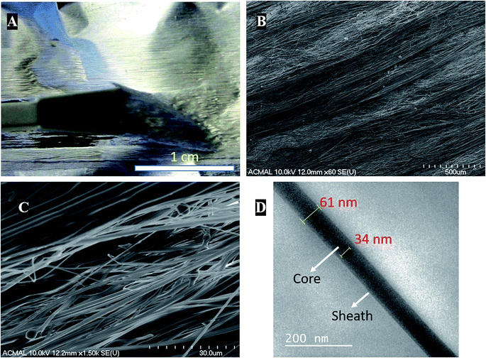
Coaxial electrospinning helps in formation of functional scaffolds from otherwise immiscible polymer blends. In the case of PCL–PANI–PVDF, a heterogenous functional scaffold composed of PCL, PVDF and PANI was formed by preparing PCL–PANI core solution and coaxially electrospinning it with PVDF sheath solution. The differential rate of solubilities of the polymers in solvents and their polarity helped in obtaining fibers with an aligned morphology. The PCL–PANI–PVDF fibers when observed by the naked eye have a repetitive pattern composed of thick diameter fibers aligned along the rotation of the cylinder during electrospinning (Fig. 1A).Visualizing the fibers under the scanning electron microscope revealed a well-aligned and dense formation of a 3D fibrillar network of PCL–PANI–PVDF (low magnification: Fig. 1B and high magnification: Fig. 1C) with periodic structural anisotropies. The morphological characterization of the PCL and PCL–PVDF samples were done using FESEM (Fig. S1†). The PCL and PCL–PVDF fibers had an aligned morphology and had no beading in the fibers. The diameter of the fibers in the PCL–PANI–PVDF scaffold was measured to be between 30 nm to 2000 nm with a deviation of 8.68° in alignment. The fibers overlapped forming multiple layers leading to a very dense three-dimensional structure for the scaffold. The morphology was obtained by controlling the jet elongation and polymer flow rate which in turn was influenced by the sol–gel and the electrospinning parameters (electric field and environmental factors).22 The solvents used for preparing the solutions have different physical and chemical properties, which alters the surface tension, subsequently affecting the jet elongation.23 Bands of larger diameter fibers were interspersed by smaller diameter fibers forming a pattern. Large diameter fibers have a lower critical uptake velocity than small diameter nanofibers.24 The uptake velocity was controlled to introduce differential alignment with the larger diameter fibers having greater alignment compared to the smaller diameter fibers, producing a repetitive pattern. Transmission electron microscopy images of the fibers revealed a coaxial fiber composed of a thick core (PCL–PANI) and a relatively thin sheath (PVDF) (Fig. 1D). The thickness of the fiber and core was measured to be 61 ± 7 nm and 35 ± 3 nm, respectively.
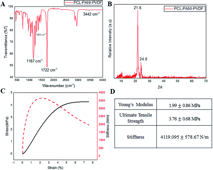
Infrared spectroscopy was used for analyzing the surface functional groups of the PCL–PANI–PVDF scaffold as seen in Fig. 2A, PCL–PVDF and PCL scaffold as seen in Fig. S2.† The spectrum from PCL–PANI–PVDF showed distinctive peaks pertaining to PCL at 1722 cm−1 (C![[double bond, length as m-dash]](https://www.rsc.org/images/entities/char_e001.gif) O stretching), 1167 cm−1 (C–O stretching), 2944 cm−1 (asymmetric CH2 stretching), 2866 cm−1 (symmetric CH2 stretching) and a strong intensity peak at 1293 cm−1 (C–O and C–C stretching in the crystalline phase of PCL). Although, the peaks of PVDF overlapped with PCL and PANI, there was a low intensity peak at 840 cm−1 corresponding to the CH2 rocking in PVDF. The N–H stretching at 3442 cm−1 was specific to PANI. The PCL–PANI–PVDF scaffold has signature peaks corresponding to the three polymers. The XRD spectra from PCL–PANI–PVDF showed major peaks at 21.6° and 24.0° (Fig. 2B). The degree of crystallinity was calculated to be 0.653 confirming that the fibers were molecularly oriented. The significant peaks corresponding to PCL and PVDF are present. The PCL–PANI–PVDF scaffold has a high draw ratio of the polymer chains while electrospinning, thereby aligning the fibers along the axis of the rotating collector. This arrangement also provides more room for alignment of the microfibrils. From the FESEM images, it can be seen that there was branching in the fibers of larger diameters which confirmed the formation of microfibrillar regions. The presence of these microfibrillation increases the crystallinity of PCL–PANI–PVDF fibers, which agrees well with the presence of peaks at 1293 cm−1 corresponding to the crystalline phase. The surface characterization of PCL and PCL–PVDF was done using XRD (Fig. S3†). The mechanical properties of the PCL–PANI–PVDF scaffold were characterized from the stress–strain–stiffness graph (Fig. 2C and D). The microfibrillation and alignment of the fibers helps provide a higher stiffness in an uniaxial direction.25 The stiffness is a very important parameter that affects the cellular responses through mechanoreceptors. The PCL–PANI–PVDF had a much higher matrix stiffness in comparison to PCL and PCL–PVDF (Fig. S4†). The PCL–PANI–PVDF scaffold had a maximum stiffness of 4119.095 ±± 578.67 N m−1. Higher matrix stiffness (>4 kN m−1) is generally favored since it promotes cell proliferation, alignment and elongation.26,27
O stretching), 1167 cm−1 (C–O stretching), 2944 cm−1 (asymmetric CH2 stretching), 2866 cm−1 (symmetric CH2 stretching) and a strong intensity peak at 1293 cm−1 (C–O and C–C stretching in the crystalline phase of PCL). Although, the peaks of PVDF overlapped with PCL and PANI, there was a low intensity peak at 840 cm−1 corresponding to the CH2 rocking in PVDF. The N–H stretching at 3442 cm−1 was specific to PANI. The PCL–PANI–PVDF scaffold has signature peaks corresponding to the three polymers. The XRD spectra from PCL–PANI–PVDF showed major peaks at 21.6° and 24.0° (Fig. 2B). The degree of crystallinity was calculated to be 0.653 confirming that the fibers were molecularly oriented. The significant peaks corresponding to PCL and PVDF are present. The PCL–PANI–PVDF scaffold has a high draw ratio of the polymer chains while electrospinning, thereby aligning the fibers along the axis of the rotating collector. This arrangement also provides more room for alignment of the microfibrils. From the FESEM images, it can be seen that there was branching in the fibers of larger diameters which confirmed the formation of microfibrillar regions. The presence of these microfibrillation increases the crystallinity of PCL–PANI–PVDF fibers, which agrees well with the presence of peaks at 1293 cm−1 corresponding to the crystalline phase. The surface characterization of PCL and PCL–PVDF was done using XRD (Fig. S3†). The mechanical properties of the PCL–PANI–PVDF scaffold were characterized from the stress–strain–stiffness graph (Fig. 2C and D). The microfibrillation and alignment of the fibers helps provide a higher stiffness in an uniaxial direction.25 The stiffness is a very important parameter that affects the cellular responses through mechanoreceptors. The PCL–PANI–PVDF had a much higher matrix stiffness in comparison to PCL and PCL–PVDF (Fig. S4†). The PCL–PANI–PVDF scaffold had a maximum stiffness of 4119.095 ±± 578.67 N m−1. Higher matrix stiffness (>4 kN m−1) is generally favored since it promotes cell proliferation, alignment and elongation.26,27
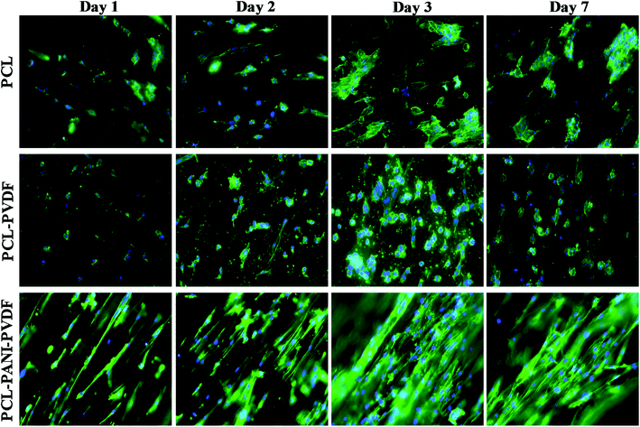
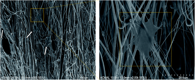
The H9c2 cells were fixed and stained with DAPI and Alexa Fluor® 488 Phalloidin to visualize the nucleus and the actin filaments respectively as seen in Fig. 3. The cell–scaffold interaction is different on each type of scaffold. The cells on PCL scaffold clumped together and lacked projections typical of cardiomyoblasts while the cells on PCL–PVDF scaffold exhibited relatively better cell alignment and cell spreading, the cells were circular, and nuclei were not elongated as inferred from Fig. S5.† Neither PCL nor PCL–PVDF scaffolds supported cell penetration into the scaffold till day 7. In the PCL–PANI–PVDF scaffold the cells appeared aligned with actin filaments stretching across the length of the fibers. The cells also appeared to have penetrated through the different layers of the scaffold with similar actin distribution. The distinct elliptical nuclei indicate nearly identical cell separation and spread across the scaffold as seen in Fig. S5.† The morphology is beneficial for cellular alignment as inferred from the cell deviation graph in Fig. S6.† The FESEM images of PCL–PANI–PVDF scaffold (Fig. 4a and b) clearly demonstrate cells attached to the aligned fibers of the scaffold. The cells were not only attached but also integrated into the scaffold confirming cellular infiltration. In addition, there was no clumping or crowding of the cells and the overall alignment and integrity of the scaffold was maintained. The FESEM images of cells on PCL and PCL–PVDF scaffolds (Fig. S7†) showed that cells had little or no cell spreading. The cells were clumped in regions and didn't infiltrate through the scaffold.
In summary, we have fabricated acellular scaffolds with mechanical anisotropy and inherent electroactive properties due to its component polymers ensuring cell penetration, migration and alignment. External stimuli or growth factors were not used to promote cell growth. The polymer blend used can be tuned to alter chemical composition and mechanical structure paving the way for research into acellular scaffolds for various applications like cardiac patches, skin grafts and organ regeneration. The scaffold also has the benefit of being readily available and can be synthesized with limited resources and stored at room temperature.
Conclusion
Here we have successfully demonstrated the alignment of cells on an acellular scaffold without the use of an external environment or additional growth factors. The scaffold is composed of a blend of three polymers: PCL, PANI and PVDF. Coaxial electrospinning was used to obtain the scaffolds with controlled surface morphology. The fibers were characterized for their surface morphology, mechanical strength, surface properties, and the cell–scaffold interaction was demonstrated using rat cardiomyoblasts (H9c2). The cell–scaffold interaction was compared to electrospun aligned PCL and PCL–PVDF scaffolds. The cells on the PCL–PANI–PVDF scaffold exhibited cellular alignment and proliferated along the direction of fibers without any external stimuli in comparison to PCL and PCL–PVDF scaffolds.Conflicts of interest
There are no conflicts to declare.Acknowledgements
We would like to thank the Department of Biomedical Engineering at Michigan Technological University and the T3N award from the Michigan Economic Development Corporation for the financial support. The author would also like to acknowledge the financial support received by Samerender Nagam Hanumantharao through the Portage Health Foundation (PHF) graduate assistantship. The work was also partially funded by financial contribution from Ken Gunther, an alumnus of Michigan Tech. We would also like to thank Paul Fraley for his help with mechanical characterization of the samples. The authors would also like to thank Owen Mills, and Edward Laitila at the Applied Chemical and Morphological Analysis Laboratory (ACMAL) at Michigan Technological University for their help in characterizing the samples.Notes and references
- B. Dhandayuthapani, Y. Yoshida, T. Maekawa and D. S. Kumar, Int. J. Polym. Sci., 2011, 19, DOI:10.1155/2011/290602.
- M. Nikkhah, F. Edalat, S. Manoucheri and A. Khademhosseini, Biomaterials, 2012, 33, 5230–5246 CrossRef CAS PubMed.
- D. W. Hutmacher, in The Biomaterials: Silver Jubilee Compendium, ed. D. F. Williams, Elsevier Science, Oxford, 2000, pp. 175–189, DOI:10.1016/B978-008045154-1.50021-6.
- G. S. Hussey, J. L. Dziki and S. F. Badylak, Nat. Rev. Mater., 2018, 3, 159–173 CrossRef CAS.
- E. S. Place, N. D. Evans and M. M. Stevens, Nat. Mater., 2009, 8, 457 CrossRef CAS PubMed.
- B. D. Riehl, J.-H. Park, I. K. Kwon and J. Y. Lim, Tissue Eng., Part B, 2012, 18, 288–300 CrossRef CAS PubMed.
- T. H. Qazi, R. Rai and A. R. Boccaccini, Biomaterials, 2014, 35, 9068–9086 CrossRef CAS PubMed.
- L. Ghasemi-Mobarakeh, M. P. Prabhakaran, L. Tian, E. Shamirzaei-Jeshvaghani, L. Dehghani and S. Ramakrishna, World J. Stem Cells, 2015, 7, 728–744 CrossRef PubMed.
- D. R. Nisbet, J. S. Forsythe, W. Shen, D. I. Finkelstein and M. K. Horne, J. Biomater. Appl., 2008, 24, 7–29 CrossRef PubMed.
- R. Gmeiner, U. Deisinger, J. Schönherr, B. Lechner, R. Detsch, A. Boccaccini and J. Stampfl, J. Ceram. Sci. Technol., 2015, 6, 75–86 Search PubMed.
- B. P. Chan and K. W. Leong, Eur. Spine J., 2008, 17(suppl. 4), 467–479 CrossRef PubMed.
- H.-I. Chang and Y. Wang, in Regenerative medicine and tissue engineering-cells and biomaterials, InTech, 2011 Search PubMed.
- S. Peng, G. Jin, L. Li, K. Li, M. Srinivasan, S. Ramakrishna and J. Chen, Chem. Soc. Rev., 2016, 45, 1225–1241 RSC.
- M. Naeimirad, A. Zadhoush, R. Kotek, R. Esmaeely Neisiany, S. Nouri Khorasani and S. Ramakrishna, J. Appl. Polym. Sci., 2018, 135, 46265 CrossRef.
- S. Agarwal, A. Greiner and J. H. Wendorff, Prog. Polym. Sci., 2013, 38, 963–991 CrossRef CAS.
- L. E. Freed, G. C. Engelmayr Jr, J. T. Borenstein, F. T. Moutos and F. Guilak, Adv. Mater., 2009, 21, 3410–3418 CrossRef CAS PubMed.
- M. A. Woodruff and D. W. Hutmacher, Prog. Polym. Sci., 2010, 35, 1217–1256 CrossRef CAS.
- P. R. Bidez, S. X. Li, A. G. MacDiarmid, E. C. Venancio, Y. Wei and P. I. Lelkes, J. Biomater. Sci. Polym. Ed., 2006, 17, 199–212 CrossRef CAS PubMed.
- P. Martins, A. C. Lopes and S. Lanceros-Mendez, Prog. Polym. Sci., 2014, 39, 683–706 CrossRef CAS.
- A. Cipitria, A. Skelton, T. R. Dargaville, P. D. Dalton and D. W. Hutmacher, J. Mater. Chem., 2011, 21, 9419–9453 RSC.
- B. Wessling, in Handbook of nanostructured materials and nanotechnology, ed. H. S. Nalwa, 2000, vol. 5, pp. 501–575 Search PubMed.
- S. A. Theron, A. L. Yarin, E. Zussman and E. Kroll, Polymer, 2005, 46, 2889–2899 CrossRef CAS.
- S.-H. Tan, R. Inai, M. Kotaki and S. Ramakrishna, Polymer, 2005, 46, 6128–6134 CrossRef CAS.
- H. Pan, L. Li, L. Hu and X. Cui, Polymer, 2006, 47, 4901–4904 CrossRef CAS.
- K. M. O. Håkansson, A. B. Fall, F. Lundell, S. Yu, C. Krywka, S. V. Roth, G. Santoro, M. Kvick, L. Prahl Wittberg, L. Wågberg and L. D. Söderberg, Nat. Commun., 2014, 5, 4018 CrossRef PubMed.
- R. G. Wells, Hepatology, 2008, 47, 1394–1400 CrossRef CAS PubMed.
- P. Pandey, W. Hawkes, J. Hu, W. V. Megone, J. Gautrot, N. Anilkumar, M. Zhang, L. Hirvonen, S. Cox, E. Ehler, J. Hone, M. Sheetz and T. Iskratsch, Dev. Cell, 2018, 44, 326–336 CrossRef CAS PubMed.
Footnote |
| † Electronic supplementary information (ESI) available. See DOI: 10.1039/c9ra07777d |
| This journal is © The Royal Society of Chemistry 2019 |


