
 Open Access Article
 This Open Access Article is licensed under a Creative Commons Attribution-Non Commercial 3.0 Unported Licence
One-pot synthesis of Cu2O/C@H-TiO2 nanocomposites with enhanced visible-light photocatalytic activity
Aoqun Jianab,
Meiling Wangab,
Leiyang Wangab,
Bo Zhangab,
Shengbo Sang *ab and
Xuming Zhang*c
*ab and
Xuming Zhang*c
aMicroNano System Research Center, College of Information and Computer, Taiyuan University of Technology, Taiyuan 030024, China. E-mail: jianaoqun@tyut.edu.cn; mlwang_001@163.com; wangleiyang@boe.com.cn; zhangbo0351@163.com; sunboa-sang@tyut.edu.cn
bKey Laboratory of Advanced Transducers and Intelligent Control System, Shanxi Province and Ministry of Education, Taiyuan University of Technology, Taiyuan 030024, China
cDepartment of Applied Physics, Hong Kong Polytechnic University, Hung Hom, Kowloon, Hong Kong, China. E-mail: xuming.zhang@polyu.edu.hk
First published on 16th December 2019
Abstract
As an environment-friendly semiconductor, titanium dioxide (TiO2), which can effectively convert solar energy to chemical energy, is a crucial material in solar energy conversion research. However, it has several technical limitations for environment protection and energy industries, such as low photocatalytic efficiency and a narrow spectrum response. In this study, a unique mesoporous Cu2O/C@H-TiO2 nanocomposite is proposed to solve these issues. Polystyrene beads ((C8H8)n, PS) are utilized as templates to prepare TiO2 hollow microspheres. Cu2O nanocomposites and amorphous carbon are deposited by a one-pot method on the surface of TiO2 hollow spheres. After the heterojunction is formed between the two semiconductor materials, the difference in energy levels can effectively separate the photogenerated e−–h+ pairs, thereby greatly improving the photocatalytic efficiency. Furthermore, due to the visible band absorption of Cu2O, the absorption range of the prepared nanocomposites is expanded to the whole solar spectrum. Amorphous carbon, as a Cu2O reduction reaction concomitant product, can further improve the electron conduction characteristics between Cu2O and TiO2. The structure and chemical composition of the obtained nanocomposites are characterized by a series of techniques (such as SEM, EDS, TEM, XRD, FTIR, XPS, DRS, PL, MS etc.). The experimental results of the degradation of methylene blue (MB) aqueous solution demonstrate that the degradation efficiency of Cu2O/C@H-TiO2 nanocomposites is about 3 times as fast as that of pure TiO2 hollow microspheres, and a more absolute degradation can be achieved. Herein, a recyclable photocatalyst with high degradation efficiency and a whole solar spectrum response is proposed and fabricated, and would find useful applications in environment protection, and optoelectronic devices.
Introduction
Due to population growth and the gradual reduction of freshwater resources, sewage treatment is an urgent issue for human society. In recent years, the application of semiconductor oxide nanostructures as photocatalysts has been considered to be a hot research topic and has demonstrated great advantages in the treatment of contaminants in water.1,2 As a kind of metal oxide semiconductor that is nontoxic, abundant, stable and photoactive, titanium dioxide (TiO2) has been widely used in the purification of water and air.3–7 More and more attention has recently focused on ordered mesoporous TiO2 frameworks with high volume crystallinity and high thermal stability.8 The mesoporous structure promotes the diffusion of reactants and products, and photocatalytic activities by promoting reaction sites on the surface of the photocatalyst. Furthermore, compared with the separated individual nanoparticles, mesoporous TiO2 may increase the recovery efficiency of the catalyst due to its continuous particle framework.9 However, TiO2 nanoparticles tend to agglomerate and are difficult to achieve a solid combination by simple mixing, which increases the possibility of recombination of e−–h+ pairs and is not conducive for the migration of photogenerated carriers. In recent years, the excellent properties of TiO2 hollow microspheres, with low density, high surface area, excellent surface permeability and high light-harvesting efficiency, are of interest to researchers.6,10–15 The large surface area provides more adsorption and reactive sites for photocatalytic reactions. The mesoporous hollow framework structure can not only promote the rapid transportation of the transmission medium, but also improve the multi-light scattering/reflection to enhance the absorption rate of light and further enhance the photocatalysis.16–18On the other hand, due to its wide band gap (usually >3 eV) of TiO2, only ultraviolet light is absorbed and employed for photocatalyst (wavelength < 400 nm, representing a maximum of 5% of energy of the solar spectrum).19,20 To take full advantage of natural solar energy, a straightforward motive is to develop visible-light-responsive photocatalytic materials and further increase the energy conversion rate. For example, noble metal-supported semiconductor composites can enhance absorption in the visible region by utilizing the localized surface plasmon resonance (LSPR) effect of the metal nanoparticles, and the Schottky junction at the contact interface can suppress electron–hole recombination.21–25 However, the complicated preparation process and high cost of noble metal nanostructure prohibits its widespread applications as an environmental treatment agent.19,26
At present, the heterojunctions formed by metal oxides with a suitable band structure and TiO2 are rising as a superior alternative. Cuprous oxide (Cu2O) is a common p-type semiconductor material with a direct band gap of 2.17 eV.21 Due to its absorption of the visible band light, Cu2O nanostructures have many applications in environmental protection, energy development and organic synthesis.27–29 Wang et al. prepared composites of cuprous oxide (Cu2O)/RGO with high photo-catalytic performances.30 Tang et al. studied an efficient visible-driven photocatalysts of Cu2O/SiNW arrays.31 Li et al. used a low temperature full solution method to prepare a ternary ZnO/Cu2O/Si nanowire array with vertical regularity.32 Experimental studies have shown that these nanostructures Cu2O (such as rhombic dodecahedra, nanoflower shape) can be uniformly dispersed on TiO2 nanosheets to form heterojunctions. Such structures facilitate charge transfer across the interface and can achieve high catalytic activity and good catalytic durability.33
In this paper, a novel one-pot method to fabricate mesoporous hollow Cu2O/C@H-TiO2 structured composites is proposed. The Cu2O nanocomposites can not only broaden the light absorption range of the composite catalyst, but also separate the e−–h+ pairs by utilizing the difference in energy band of TiO2. On the other hand, the amorphous carbon layer on the composite catalyst can improve the electronic conductivity in the catalyst, thereby making the composite photocatalyst has a higher photocatalytic efficiency. According to the previous research,34,35 a schematic diagram of the separation and transport of photogenerated charge carriers on Cu2O/C@H-TiO2 is schematically shown in Fig. 1a. The unique Cu2O/C@H-TiO2 composite material in hollow structure, improving the adsorption of pollutants and the efficiency of solar energy absorption, will have great application potential for wastewater treatment, air purification and water splitting.
 | ||
| Fig. 1 (a) Schematic diagram for photogenerated charge carriers separation and transportation, (b) synthesis route of Cu2O/C@H-TiO2 spherical photocatalyst. | ||
The synthetic route of Cu2O/C@H-TiO2 photocatalyst is shown in Fig. 1b. First, tetrabutyl titanate (TBOT) is electrostatically adsorbed onto polystyrene beads ((C8H8)n, PS) and then calcined to form TiO2 hollow microspheres. Next, the amorphous carbon and Cu2O nanocomposites coatings are hydrothermally synthesized onto the TiO2 hollow microspheres by a one-pot process. The loss of the samples can be significantly reduced by simplification of the preparation steps.
Experiment
Reagents: C6H12O6; CuCl2·2H2O, NaOH, polystyrene beads ((C8H8)n, PS); tetrabutyl titanate (C16H36O4Ti, TBOT), ammonia (NH3·H2O), ethyl alcohol absolute (C2H5OH), acetonitrile (C2H3N), deionized water was used for all experiments.Synthesis of hollow TiO2 microspheres
Refer to previous research results,36 H-TiO2 microspheres were prepared according to the electrostatic adsorption and calcination methods, in which 0.024 g polystyrene (PS) beads were added into a mixture solution containing 75 mL ethanol, 25 mL acetonitrile and 300 μL ammonia to configure solution A under vigorous stirring for 3 h. 0.5 mL TBOT was added into a mixture solution containing 15 mL ethanol and 5 mL acetonitrile to configure solution B. After stirring for 5 min, the solution B were slowly added dropwise to the solution A, and the ultimately solution were isolated by centrifugation and washed with ethanol and deionized water to obtain TiO2@PS microspheres. The powder were dispersed in a reaction kettle containing deionized water at 80 °C for 24 h, then centrifuged and dried at 80 °C. The TiO2 hollow microspheres (H-TiO2) were obtained by calcining the dried powder in a muffle furnace at 400 °C for 4 h.Synthesis of Cu2O/C@H-TiO2 microspheres
Three different qualities of CuCl2·2H2O were dispersed in three beakers with 20 mL of deionized water, respectively. The corresponding H-TiO2 microspheres and a certain amount of NaOH were then added to the CuCl2·2H2O solution by magnetic stirring for 1 h. Then C6H12O6·H2O was dispersed into the green suspension during stirring. The resulting suspension was transferred to a 50 mL polytetrafluoroethylene lined stainless steel autoclave. The hydrothermal treatment was carried out at 100 °C for 8 h. The product was collected and washed several times with deionized water and ethanol and dried in vacuum at 80 °C to prepare 4 wt%, 8 wt% and 20 wt% Cu2O/C@H-TiO2 microspheres.Characterization
The morphology of the synthesized product was investigated using a scanning electron microscope (SEM) images and energy dispersive spectroscopy (EDS), which were acquired with a Hitachi model SU8010. The crystalline phase and the phase purity of the samples was recorded by high-resolution transmission electron microscopy (HR-TEM, JEM-1400 plus) and X-ray diffraction (XRD, Rigaku-D/max-2500) within 2θ range from 20° to 80° by using a Cu Kα radiation. UV-vis diffuse reflectance spectroscopy (DRS) of the samples were retrieved from a UV-2600 spectrophotometer with an integrating sphere accessory in the range of 300 to 800 nm. The X-ray photoelectron spectroscopy (XPS) spectra were performed on Thermo ESCALAB 250XI System to determine the chemical status of the as-prepared Cu2O/C@H-TiO2 microspheres. N2 adsorption–desorption isotherms were measured on a Micromeritics BK122W automatic adsorption instrument at 120 °C for 8 h. Fourier-transform infrared (FTIR) spectra were evaluated using a Bruker Vector 33 FT-IR spectrophotometer in the range of 4000–400 cm−1 with a resolution of 4 cm−1 using the conventional KBr pellet technique. Photoluminescence (PL) spectra and time resolved photoluminescence spectra (TRPL) were recorded on a fluorescence spectrometer (FLS 980-STM, Edinburgh instruments).The three-electrode system was immersed in 0.5 M Na2SO4 in which the sample was prepared on a ITO glass as a working electrode, a platinum plate as a counter electrode, and a saturated calomel electrode as a reference electrode to evaluate photoelectric properties.
The methylene blue (MB) aqueous solution of 20 mg L−1 was photodegraded in a 500 mL quartz photoreactor at 25 °C. The photocatalyst of 20 mg was dispersed in a 50 mL MB solution, and stirred for 30 min in a dark environment to establish an adsorption–desorption equilibrium, followed by irradiation with a Xe lamp (300 nm < λ < 1100 nm) for photocatalytic reaction. The sample was sampled every 10 min under the conditions of constant temperature of circulating water. After removing the catalyst by centrifugation, the supernatant was measured for absorbance using an UV-vis spectrophotometer (Cary 100, Varian) on photodegradation at 662 nm to obtain the degradation rate. Finally, the catalytic efficiencies of the synthesized catalysts were summarized and compared.
Results and discussion
Fig. 2 presents the corresponding SEM and HR-TEM images and EDS analysis monitoring the formation of as prepared H-TiO2 microspheres and Cu2O/C@H-TiO2 microspheres. It can be seen from Fig. 2a that the PS spheres are regular and uniform spheres with an average diameter of about 4.56 μm. The fabricated core–shell microspheres PS@TiO2 is shown in Fig. 2b. The surface of the microspheres become a little bit rough. The particle size is obviously enlarged (about 5.22 μm), indicating that TiO2 layer is indeed deposited on the surface of the template polymer PS, and the thickness of coated TiO2 layer is about 0.11 μm. After further calcination, the PS pellets are burned and decomposed, only TiO2 shells are left behind. The TiO2 shells shrink obviously after further crystallization. The average particle size of the hollow microspheres is about 3.97 μm (in Fig. 2c). A distinct hollow structure can be observed by crushing the calcined H-TiO2 microspheres with tweezers (inset in Fig. 2c). During the calcination of PS@TiO2 core–shell microspheres, the sample quickly loses a large amount of water in a short time. Some spheres are likely to collapse with the rapid disappearance of PS. Therefore, the heating rate of the calcination temperature and the pre-high temperature treatment before the calcination are elaborated to enhance the product yield of TiO2 sphere shells. The fabricated Cu2O/C@H-TiO2 microspheres are presented in Fig. 2d and e. Compared with the H-TiO2 microspheres, the average diameter of Cu2O/C@H-TiO2 microspheres is about 4.80 μm, and the surface of the spheres becomes rougher. The EDS analysis offered in Fig. 2f confirms that the elements C, O, Ti, Cu exist on the surface of the microspheres. In order to further analyze the interface structure and material composition, a high-resolution transmission electron microscope (HR-TEM) image of the Cu2O/C@H-TiO2 composite is presented in Fig. 2g. The lattice distances of 0.25 nm and 0.35 nm in the figure correspond to the (111) and (101) planes of Cu2O and TiO2, respectively.37 This shows the well-developed interfaces between Cu2O and the TiO2. In addition, a carbon with a lattice spacing of 0.34 nm is also detected here. This is part of the product produced during the dehydration and polycondensation of glucose molecules. | ||
| Fig. 2 The SEM images of (a) PS spheres, (b) PS@TiO2 microspheres, (c) hollow TiO2 (H-TiO2) microspheres, (d and e) Cu2O/C@H-TiO2 microspheres, (f) the EDS images of Cu2O/C@H-TiO2 microspheres, (g) HR-TEM images on Cu2O/C@H-TiO2. | ||
Fig. 3a shows the crystal structure of the H-TiO2, 4 wt% Cu2O/C@H-TiO2, 8 wt% Cu2O/C@H-TiO2, 20 wt% Cu2O/C@H-TiO2 by XRD patterns. As can be seen all the diffraction peaks of the samples at 2θ = 25.267°, 37.702°, 47.975°, 53.912°, 54.966°, 62.640°, 68.809°, 70.274°, 75.116° are corresponding to anatase TiO2, indexed very well to JCPDS card no. 21-1272.8,34 But no obvious Cu2O diffraction peaks are found in 4 wt% Cu2O/C@H-TiO2, 8 wt% Cu2O/C@H-TiO2 due to the limited amount of Cu2O. However, for 20 wt% Cu2O/C@H-TiO2, the peaks of Cu2O can be observed at 2θ = 29.581°, 36.413°, 42.352°, 61.383°, 73.525°, 77.366°.29 In addition, with the increase of the amount of Cu2O and carbon, a diffraction peak about graphitic carbon is detected at a position of about 2θ = 27.4°. This is consistent with the HR-TEM results, which indicates that a small amount of graphitic carbon is formed in the amorphous carbon.38 The Fourier-transform IR (FTIR) spectra of samples are presented in Fig. 3b. The broad absorption peak at approximately 3420 cm−1 band can be assigned to O–H stretching vibration in the alcohol group as well as the intercalated or adsorbed water molecules in the samples.39,40 The signal at 700 cm−1 is characteristic of the O–Ti–O lattice formation. The peak value of 1632 cm−1 is attributed to the surface –OH or water bending mode of the four samples. The peak of 623 cm−1 is corresponded to the stretching of copper(I)–O bond in Cu2O/C@H-TiO2, indicating the formation of Cu2O.40 This observation is consistent well with the results obtained by SEM, EDS, XRD and HR-TEM.
 | ||
| Fig. 3 XRD patterns (a) and FTIR spectra (b) of the photocatalysts. | ||
To further explore the composition and chemical state of elements in Cu2O/C@H-TiO2 samples, X-ray photoelectron spectroscopy (XPS) analysis is conducted and illustrated in Fig. 4. The survey spectrum (Fig. 4a) demonstrates that the Cu2O/C@H-TiO2 samples contain C, O, Ti and Cu element. More specifically, as presented in Fig. 4b, the high-resolution of Ti2p shows two peaks at binding energies of 463.8 eV and 461.5 eV, corresponding to Ti2p1/2 and Ti2p3/2 spin-orbital splitting photoelectrons. Separation between Ti2p1/2 and Ti2p3/2 (approximately 6.0 eV) suggests a normal state of Ti4+ in the Cu2O/C@H-TiO2 microspheres.2,41 Fig. 4c demonstrates the high-resolution XPS spectrum Cu2p of 936.7 and 956.8 eV assigned to Cu2p3/2 and Cu2p1/2, respectively. Notably, according to previous reports,34 the binding energy of Cu+ is located at 934 and 952.5 eV, therefore, the measured Cu2p binding energy may be the result of an adjustment synergy between the heterojunction structure between Cu2O and TiO2 and the amorphous carbon doping.19,37,42
 | ||
| Fig. 4 (a) The XPS images of Cu2O/C@H-TiO2 microspheres. Fine scan XPS spectra of (b) Cu2p; (c) Ti2p of Cu2O/C@H-TiO2 microspheres. | ||
The Fig. 5 indicates the N2 adsorption–desorption isotherms and pore size distributions of H-TiO2 and Cu2O/C@H-TiO2. According to the 1985 IUPAC classification, both isotherms show type IV adsorption isotherms and H2 type hysteresis loops.8,43 The absorption/desorption curves are plotted in orange and blue respectively. Since these two curves are not closed, the hysteresis loop demonstrates that the synthesized material is mesoporous. It can be seen that the specific surface area of Cu2O/C@H-TiO2 is smaller than that of H-TiO2. The reduction in surface area may indicate the adsorption of amorphous carbon and Cu2O within the mesopores, which causes the partial loss of mesoporosity. The BJH desorption pore size distribution are shown in the insets of Fig. 5. For H-TiO2, the narrow pore diameters are mainly distributed at 3–10 nm, and the narrow pore size is unchanged in the case of Cu2O/C@H-TiO2. The results above suggest that the mesoporous structure is retained after the introduction of Cu2O nanocomposites and amorphous carbon. It is encouraging to find that the prepared composite material has an open mesoporous structure, which can make a fast transmission medium, provide more active sites to adsorb organic molecules, and can improve multiple light scattering/reflection to enhance light absorb.
 | ||
| Fig. 5 N2 physisorption isotherms (a) of H-TiO2, (b) of Cu2O/C@H-TiO2. | ||
The optical property of the composite is characterized by UV-vis diffuse reflectance spectroscopy (DRS). The absorption spectra of H-TiO2 and Cu2O/C@H-TiO2 microsphere composites are presented in Fig. 6. All the samples have strong absorption in the ultraviolet region, which is mainly due to the absorption of H-TiO2. Compared with pure H-TiO2 spheres, the Cu2O/C@H-TiO2 nanocomposites samples have a stronger absorption spectrum in the visible range. This may be attributed to the presence of amorphous carbon and Cu2O in the nanocomposites. In Cu2O/C@H-TiO2 nanocomposites, Cu2O can absorb visible light and promote the separation of photogenerated e−–h+ pairs by forming a heterojunction with H-TiO2. However, when the compounding amount increases to 20 wt% by weight, the absorbance is not significantly improved, which may be because an excessive amount of compounding will bring about a new carrier recombination center, or an excessive amount of Cu2O and amorphous carbon will affect the adjustment of light in the mesoporous hollow structure, thereby reducing light absorption. According to the absorption spectra of the photocatalysts, the band gap energy of all photocatalysts can be derived from the relationship between light energy (αhν)2 and photon energy hν (in the Fig. 6b). The band gap energies of H-TiO2, Cu2O, 4 wt%, 8 wt%, and 20 wt% Cu2O/C@H-TiO2 are calculated to be 3.02, 1.98, 1.94, 1.72, and 1.72 eV, respectively. And the Eg of Cu2O/C@H-TiO2 nanocomposites are smaller than H-TiO2. The narrowing of the bandgap Eg may be due to electron transfer transition between H-TiO2, Cu2O and amorphous carbon (see Fig. 1a). Therefore, it can be inferred that nanocomposites photocatalyst Cu2O/C@H-TiO2 can absorb visible light more effectively and may have higher photocatalytic activity than pure H-TiO2.
 | ||
| Fig. 6 (a) UV-vis absorption spectra of all the samples, (b) Tauc plots calculated from (a), (c) Mott–Schottky plots measured under 1000 Hz of the photoanodes. | ||
The Mott–Schottky (MS) patterns of the nanocomposites are measured to investigate its flat band potential and charge density,44–50 as shown in Fig. 6c. The H-TiO2 and other Cu2O/C@H-TiO2 nanocomposites materials show typical n-type positive slopes, and Cu2O is a p-type negative slope. The charge density (Nd) is achieved based on following formula:
| Nd = (2/eε0ε)[d(1/C2)/dV]−1 | (1) |
To further understand the charge transfer in all samples, photoluminescence spectroscopy (PL) measurements are concluded at room temperature.51 Fig. 7a shows the steady state PL spectrum of all samples collected at an excitation wavelength of 270 nm. It can be seen that the PL intensity of the Cu2O/C@H-TiO2 samples are greatly suppressed compared with pure H-TiO2 and Cu2O samples, indicating decreasing the recombination rate of the photogenerated carriers. Significantly, the PL intensity gradually decreased as the loaded amount of Cu2O and amorphous carbon increased from 0 wt% to 8 wt%, and then rose further increased to 20 wt%. This indicates that introduction of Cu2O and amorphous carbon in an appropriate amount results in a decrease in charge recombination rate, and more photogenerated carriers may be transported to the surface of the photocatalyst to participate in the photocatalytic reaction. The higher PL strength of 20 wt% Cu2O/C@H-TiO2 may be due to the recombination center of the carriers introduces by the loading of excess Cu2O and amorphous carbon. In addition, time resolved photoluminescence spectroscopy (TRPL) measurements are also performed, as shown in Fig. 7b. The 8 wt% Cu2O/C@H-TiO2 nanocomposites shows the longest decay time (0.567 ns) in all samples after fitting the curve with the exponential model, indicating a lower recombination rate of generated e−–h+ pairs. These results are consistent well with the DRS and MS carried out above.
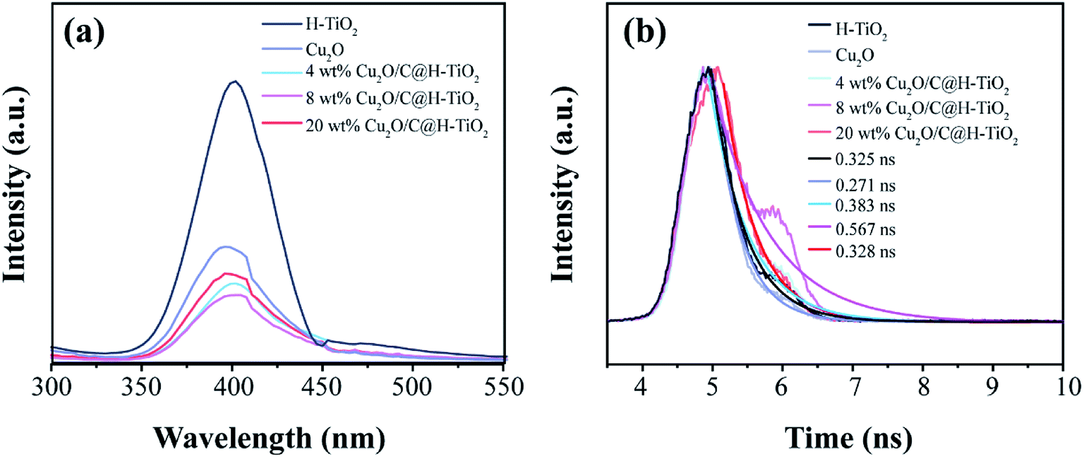 | ||
| Fig. 7 (a) PL emission spectra and (b) time-resolved fluorescence spectra of all the samples. | ||
In Fig. 8a, pure H-TiO2 and Cu2O have lower photocurrent density values of 0.67 and 1.2 μA cm−2 in a 0.5 M Na2SO4 electrolyte through a three-electrode system at 0 V SCE, respectively. And they are accompanied by obvious current spikes (especially H-TiO2). This proves that they have a high photo-generated charge recombination rate. However, for the nanocomposites photocatalyst Cu2O/C@H-TiO2, the photocurrents are high and stable. This indicates that Cu2O and amorphous carbon enhances the light absorption rates in photocatalysts and promote carrier separation. When the loading is 8 wt%, the photocatalyst exhibits higher photocurrent density (5.6 μA cm−2), which is about 8 times and 4.7 times that of pure H-TiO2 and Cu2O photocatalysts, respectively. In addition, the decrease in the photocurrent of the 20 wt% Cu2O/C@H-TiO2 photocatalyst indicates that excessive Cu2O and amorphous carbon loading are not conducive to effective charge separation, which is consistent with other characteristics described above.
 | ||
| Fig. 8 (a) Current density–time (I–t) measured in 0.5 M Na2SO4 electrolyte; (b) photocatalytic degradation of MB in the presence of different prepared photocatalysts; (c) photocatalyst stability under photodegradation, and (d) catalytic activity of photocatalysts with different scavengers. | ||
All the photocatalysts have an obvious MB removal efficiency when they are dispersed in the solution under the light irradiation. And a blank experiment is also carried out to eliminate the self-photolysis of MB. The 8 wt% Cu2O/C@TiO2 nanocomposites have better photocatalytic activity than the other photocatalysts as time passes by. Its degradation efficiency at 50 min is as 3 times and 2.3 times as those of H-TiO2 and 4 wt% Cu2O/C@H-TiO2, respectively, and the degradation is close to 100% at 100 min. The improvement of the photocatalytic performance of the combined nanoparticles is mainly due to the charge transition at the interface between Cu2O and TiO2 with a matching band structure. Another reason attributes to the amorphous carbon particles at the interface of heterojunction improve the conduction properties of electrons, thus facilitating effective photoexcitation e−–h+ separation.
As the amount of Cu2O and amorphous carbon grows from 0 wt% to 8 wt%, the catalytic performances of the composite photocatalyst gradually enhances. When the amount of Cu2O and amorphous carbon reaches 20 wt%, the photocatalytic ability drops and is even smaller than that of H-TiO2. This may be because excessive Cu2O nanocomposites will introduce new carrier recombination centers and block the pore structure of H-TiO2, which will affect the light absorption rate of H-TiO2, thus reducing the photocatalytic efficiency.
The reusability and stability of photocatalysts are crucial considerations for practical applications. Taking the 8 wt% Cu2O/C@H-TiO2 photocatalyst as an example, a cycle test of MB degradation is carried out. In Fig. 8c, the photocatalytic degradation activity decreased by less than 15% after 5 cycles of the test, indicating higher light stability. The effects of various active species on the degradation of MB in this experiment are studied in Fig. 8d. Triethanolamine (TEOA, 0.01 mol L−1), isopropyl alcohol (IPA, 0.02 mol L−1), and p-benzoquinone (BZQ, 0.1 mmol L−1) are used as scavengers of photogenerated holes (h+), hydroxyl radical (·OH), and superoxide radicals (·O2−), respectively.52–54 Meanwhile, the experiment with no scavenger under the same experimental conditions is carried out for compared. The addition of TEOA and BZQ in the experiment cause a significant decrease in photocatalytic degradation, indicating that photogenerated holes (h+), and superoxide radicals (·O2−) play a major role in the degradation of MB. Furthermore, the addition of IPA do not significantly affect the degree of degradation of MB, which means hydroxyl radical (·OH) is not the main active substance in this photocatalytic degradation.
Conclusion and outlook
In this paper, mesoporous Cu2O/C@H-TiO2 nanocomposites is proposed. Amorphous carbon and Cu2O nanocomposites are simultaneously composited onto TiO2 microspheres by a one-pot reaction. The structure, crystal phase and chemical state of the composite photocatalyst are confirmed by various characterizations. The photocatalytic performance of prepared sample is tested by MB degradation, and the photocatalytic enhancement mechanism is also analyzed. It is found that the optimized loading of Cu2O nanocomposites and amorphous carbon can enhance the photocatalytic efficiency of the composite catalyst. The Cu2O nanocomposites not only broaden the light absorption range of the composite catalyst, but also separate the e−–h+ pairs by utilizing the difference in energy band of the TiO2. Furthermore, the amorphous carbon particles on the composite catalyst can improve the electronic conductivity of the catalyst, thereby making the composite photocatalyst has a higher photocatalytic efficiency. Due to its significantly improved photocatalytic performance and simple preparation, the mesoporous Cu2O/C@H-TiO2 nanocomposites would find useful applications in environment protection and optoelectronic devices.Availability of data and material
All data generated or analysed during this study are included in this published article.Authors' contributions
Aoqun Jian and Xuming Zhang designed the experiments; Meiling Wang and Leiyang Wang performed the experiments; Meiling Wang and Bo Zhang analyzed the data; Meiling Wang wrote the paper; Shengbo Sang and Aoqun Jian discussed the results and commented on the manuscript. All authors read and approved the final manuscript.Conflicts of interest
The authors declare that they have no competing interests.Acknowledgements
This study was financially supported by the National Natural Science Foundation of China (No. 61971301, 51622507), 863 project (2015AA042601), Excellent Talents Technology Innovation Program of Shanxi Province (201805D211021), and Research Grants Council of Hong Kong (N_PolyU505/13, 152184/15E, 152127/17E and 152126/18E).References
- G. Yang, Z. Yan and T. Xiao, Appl. Surf. Sci., 2012, 258, 8704–8712 CrossRef CAS.
- C. Liu, D. Yang, Y. Jiao, Y. Tian, Y. Wang and Z. Jiang, ACS Appl. Mater. Interfaces, 2013, 5, 3824–3832 CrossRef CAS PubMed.
- Y. Ma, X. Wang, Y. Jia, X. Chen, H. Han and C. Li, Chem. Rev., 2014, 114, 9987–10043 CrossRef CAS PubMed.
- F. X. Xiao, S. F. Hung, J. Miao, H. Y. Wang, H. Yang and B. Liu, Small, 2015, 11, 554–567 CrossRef CAS PubMed.
- M. M. Khan, S. F. Adil and A. Al-Mayouf, J. Saudi Chem. Soc., 2015, 19, 462–464 CrossRef.
- R. Yang, J. Cai, K. Lv, X. Wu, W. Wang, Z. Xu, M. Li, Q. Li and W. Xu, Appl. Catal., B, 2017, 210, 184–193 CrossRef CAS.
- S. M. Gupta and M. Tripathi, Chin. Sci. Bull., 2011, 56, 1639–1657 CrossRef CAS.
- H. Liu, W. Li, D. Shen, D. Zhao and G. Wang, J. Am. Chem. Soc., 2015, 137, 13161–13166 CrossRef CAS PubMed.
- A. A. Ismail and D. W. Bahnemann, J. Mater. Chem., 2011, 21, 11686–11707 RSC.
- H. Li, J. Li, Y. Zhu, W. Xie, R. Shao, X. Yao, A. Gao and Y. Yin, Anal. Chem., 2018, 90, 5496–5502 CrossRef CAS PubMed.
- B.-X. Lei, L.-L. Zeng, P. Zhang, X.-F. Zheng, Y.-S. Wu, J. Fu and Z.-F. Sun, RSC Adv., 2014, 4, 29099–29106 RSC.
- S. Li, J. Chen, F. Zheng, Y. Li and F. Huang, Nanoscale, 2013, 5, 12150–12155 RSC.
- X. Jiang, C. Li, S. Liu, F. Zhang, F. You and C. Yao, RSC Adv., 2017, 7, 24598–24606 RSC.
- Y. Bao, Q. L. Kang, J. Z. Ma and C. Liu, Ceram. Int., 2017, 43, 8596–8602 CrossRef CAS.
- J. Yu and J. Zhang, Dalton Trans., 2010, 39, 5860–5867 RSC.
- B. Fang, Y. Xing, A. Bonakdarpour, S. Zhang and D. P. Wilkinson, ACS Sustainable Chem. Eng., 2015, 3, 2381–2388 CrossRef CAS.
- B. Fang, A. Bonakdarpour, K. Reilly, Y. Xing, F. Taghipour and D. P. Wilkinson, ACS Appl. Mater. Interfaces, 2014, 6, 15488–15498 CrossRef CAS PubMed.
- B. Fang, J. H. Kim, M. S. Kim and J. S. Yu, Acc. Chem. Res., 2012, 46, 1397–1406 CrossRef PubMed.
- K. Zhao, S. Zhao, J. Qi, H. Yin, C. Gao, A. M. Khattak, Y. Wu, A. Iqbal, L. Wu, Y. Gao, R. Yu and Z. Tang, Inorg. Chem. Front., 2016, 3, 488–493 RSC.
- U. I. Gaya and A. H. Abdullah, J. Photochem. Photobiol., C, 2008, 9, 1–12 CrossRef CAS.
- W.-Y. Cheng, T.-H. Yu, K.-J. Chao and S.-Y. Lu, Int. J. Hydrogen Energy, 2013, 38, 9665–9672 CrossRef CAS.
- S. Kumar, M. Anija and A. K. Sood, Plasmonics, 2013, 8, 1477–1483 CrossRef CAS.
- Y. Lu, H. Yu, S. Chen, X. Quan and H. Zhao, Environ. Sci. Technol., 2012, 46, 1724–1730 CrossRef CAS PubMed.
- S. K. Cushing, J. Li, F. Meng, T. R. Senty, S. Suri, M. Zhi, M. Li, A. D. Bristow and N. Wu, J. Am. Chem. Soc., 2012, 134, 15033–15041 CrossRef CAS PubMed.
- Z. W. Seh, S. Liu, M. Low, S. Y. Zhang, Z. Liu, A. Mlayah and M. Y. Han, Adv. Mater., 2012, 24, 2310–2314 CrossRef CAS PubMed.
- F. Sordello and C. Minero, Appl. Catal., B, 2015, 163, 452–458 CrossRef CAS.
- H. Zhang, Q. Zhu, Y. Zhang, Y. Wang, L. Zhao and B. Yu, Adv. Funct. Mater., 2007, 17, 2766–2771 CrossRef CAS.
- M. Singh, D. Jampaiah, A. E. Kandjani, Y. M. Sabri, E. Della Gaspera, P. Reineck, M. Judd, J. Langley, N. Cox, J. van Embden, E. L. H. Mayes, B. C. Gibson, S. K. Bhargava, R. Ramanathan and V. Bansal, Nanoscale, 2018, 10, 6039–6050 RSC.
- L. Sinatra, A. P. LaGrow, W. Peng, A. R. Kirmani, A. Amassian, H. Idriss and O. M. Bakr, J. Catal., 2015, 322, 109–117 CrossRef CAS.
- A. Wang, X. Li, Y. Zhao, W. Wu, J. Chen and H. Meng, Powder Technol., 2014, 261, 42–48 CrossRef CAS.
- C. H. Tang, P. H. Hsiao and C. Y. Chen, Nanoscale Res. Lett., 2018, 13, 312 CrossRef PubMed.
- P. H. Hsiao, T. C. Li and C. Y. Chen, Nanoscale Res. Lett., 2019, 14, 244 CrossRef PubMed.
- L. Ma, G. Wang, C. Jiang, H. Bao and Q. Xu, Appl. Surf. Sci., 2018, 430, 263–272 CrossRef CAS.
- H. Yin, X. Wang, L. Wang, Q. Nie, Y. Zhang and W. Wu, Mater. Res. Bull., 2015, 72, 176–183 CrossRef CAS.
- H. Xu, S. Ouyang, L. Liu, D. Wang, T. Kako and J. Ye, Nanotechnology, 2014, 25, 165402 CrossRef PubMed.
- P. Wang, D. Chen and F. Q. Tang, Langmuir, 2006, 22, 4832–4835 CrossRef CAS PubMed.
- Y. Wang, J. Tao, X. Wang, Z. Wang, M. Zhang, G. He and Z. Sun, Ceram. Int., 2017, 43, 4866–4872 CrossRef CAS.
- J. Cheng, Y. Wang, Y. Xing, M. Shahid and W. Pan, RSC Adv., 2017, 7, 15330–15336 RSC.
- W. Wang, D. Xu, B. Cheng, J. Yu and C. Jiang, J. Mater. Chem. A, 2017, 5, 5020–5029 RSC.
- K. Dong, J. He, J. Liu, F. Li, L. Yu, Y. Zhang, X. Zhou and H. Ma, J. Mater. Sci., 2017, 52, 6754–6766 CrossRef CAS PubMed.
- Q. Jiang, L. Li, J. Bi, S. Liang and M. Liu, Nanomaterials, 2017, 7, 24 CrossRef PubMed.
- Z. Geng, Y. Zhang, X. Yuan, M. Huo, Y. Zhao, Y. Lu and Y. Qiu, J. Alloys Compd., 2015, 644, 734–741 CrossRef CAS.
- Y. Li, L. Wang, J. Liang, F. Gao, K. Yin and P. Dai, Nanoscale Res. Lett., 2017, 12, 531 CrossRef PubMed.
- S. Zhang, Z. Liu, M. Ruan, Z. Guo, L. E, W. Zhao, D. Zhao, X. Wu and D. Chen, Appl. Catal., B, 2020, 262 Search PubMed.
- Z. Li, Q. Yang, C. Chen, Z. Zhang and X. Fang, Chin. J. Catal., 2019, 40, 875–885 CrossRef CAS.
- Y. X. Lin, W. J. Feng, J. J. Zhang, Z. H. Xue, T. J. Zhao, H. Su, S. I. Hirano, X. H. Li and J. S. Chen, Angew. Chem., Int. Ed. Engl., 2018, 57, 12563–12566 CrossRef CAS PubMed.
- X. Wang, L. Mayrhofer, M. Hoefer, S. Estrade, L. Lopez-Conesa, H. Zhou, Y. Lin, F. Peiró, Z. Fan, H. Shen, L. Schaefer, M. Moseler, G. Braeuer and A. Waag, Adv. Energy Mater., 2019, 9, 1900725 CrossRef.
- S. Wang, L. Li, Z. Zhu, M. Zhao, L. Zhang, N. Zhang, Q. Wu, X. Wang and G. Li, Small, 2019, 15, 1804515 CrossRef PubMed.
- R. Yang, Y. Ji, Q. Li, Z. Zhao, R. Zhang, L. Liang, F. Liu, Y. Chen, S. Han, X. Yu and H. Liu, Appl. Catal., B, 2019, 256 Search PubMed.
- Z. Zeng, Y. Yan, J. Chen, P. Zan, Q. Tian and P. Chen, Adv. Funct. Mater., 2019, 29, 1806500 CrossRef.
- Y. Su, Z. Zhao, S. Li, F. Liu and Z. Zhang, Inorg. Chem. Front., 2018, 5, 3074–3081 RSC.
- T. Takizawa, T. Watanabe and K. Honda, J. Phys. Chem. C, 1978, 82, 1391–1396 CrossRef CAS.
- X. Zhang, D. Xu, Y. Jia and S. Zhang, RSC Adv., 2017, 7, 30392–30396 RSC.
- X. Zhang, D. Xu, D. Huang, F. Liu, K. Xu, H. Wang and S. Zhang, J. Am. Ceram. Soc., 2017, 100, 2781–2789 CrossRef CAS.
| This journal is © The Royal Society of Chemistry 2019 |