 Open Access Article
Fabrication of uniform urchin-like N-doped NiCo2O4@C hollow nanostructures for high performance supercapacitors
XiaoYu Hua,
MiaoFeng Huanga,
XianHe Mengb and
Xin Ju *a
*a
aSchool of Mathematics and Physics, University of Science and Technology Beijing, Beijing 100083, China. E-mail: jux@ustb.edu.cn; Fax: +86 10 62333921; Tel: +86 10 62333921
bCollege of Materials and Chemistry, China Jiliang University, Hangzhou 310018, China
First published on 19th December 2019
Abstract
Transition metal oxides are commonly used in electrochemical energy storage materials, but there are still many drawbacks that impede a wide range of applications. Heteroatom doping can significantly improve its performance. Herein, we have successfully prepared highly uniform N-doped NiCo2O4@C hollow nanostructures for supercapacitors by a two-step hydrothermal treatment associated with successive annealing process. Prepared N-doped NiCo2O4@C materials exhibited an admirable specific capacitance of 1028 F g−1 at a current density of 3 A g−1, with 625 F g−1 remaining even at high current density of 20 A g−1. Besides, this composite showed good electrochemical stability with capacity retention of 84% after 5000 cycles repetitive galvanostatic charge–discharge test at 10 A g−1. An asymmetric supercapacitor was assembled by the N-doped NiCo2O4@C electrode, attached activate carbon (AC) as a counter electrode, exhibiting a high energy density of 26.67 W h kg−1 at a power density of 402 W kg−1. The improvement of electrochemical performance is ascribed to the co-doping of nitrogen and carbon atoms. These results indicate that N-doped NiCo2O4@C can be employed as an ideal electrode material for electrochemical energy storage.
1. Introduction
In recent years, with the increase in population and lack of resources, an unprecedented energy crisis has developed. Energy reserves and conversion equipment represented by supercapacitors are rapidly developing. Supercapacitors can be typically categorized into electrical double-layer capacitors (EDLCs) and pseudocapacitors.1,2 The EDLCs store charges through ion adsorption at the electrode/electrolyte interface of the high surface area porous carbon materials. It shows higher power density and lower capacitance.3,4 So researchers are inclined to develop pseudocapacitors that employ transition metal oxides5–7/hydroxides or conductive polymers as the electrodes and store energy through reversible faradaic redox reactions at surface/near-surface.8–10Among various metal oxides, binary nickel–cobalt oxide (NiCo2O4) electrode materials have attracted much attention due to their superior theoretical specific capacitance,11–15 environmental friendliness and low cost. Especially, compared with monometallic nickel or cobalt oxides,5,16–18 NiCo2O4 exhibits remarkable electrochemical performance owing to synergistic effects between the two elements.19 Sethi et al. used a facile hydrothermal method to synthesize NiCo2O4 nanorod arrays, a satisfactory specific capacitance value of 440 F g−1 was achieved at a scan rate of 5 mV s−1.13 Qi et al. designed and synthesized NiCo2O4 hollow microspheres with adjustable numbers and thickness of shell, showing that the best electrochemical performance was 720 F g−1 when the current density was 2 A g−1.20
However, the low electronic conductibility and weak cycling performance of NiCo2O4 electrodes still hinder its large-scale application.21,22 In order to seek a solution to the problem, some effective strategies have been proposed. According to previous reports, the introduction of porous carbon material into NiCo2O4 not only enlarges the specific surface area of the material, increases the active site, but also improves the conductivity of the electrode material.23–25 For instance, with the advantages of good electrical conductivity of activated carbon and high capacitance of NiCo2O4, a series of NiCo2O4/AC composites were prepared by Xu et al.26 A novel hybrid nanostructure consisting of reduced graphene oxide (rGO) decorated on NiCo2O4 mesoporous nanosheets supported by Ni foam were designed by Zhang et al.27 In addition, the incorporation of nitrogen atom leads to the introduction of additional pseudocapacitance for the reversible redox reaction, so capacitive characteristics of electrode materials are significantly improved.28–30
Herein we chose to utilize dopamine, which contains catechol and amine functional groups,8,31–33 as a suitable precursor for the synthesis of nitrogen-doped carbon materials. The polydopamine (PDA) formed by self-polymerization under alkaline conditions possesses strong adhesion and can be applied to almost any surface to form a layer of tunable thickness.34–38 Therefore, we confirmed a preparation strategy to obtain N-doped carbon coated NiCo2O4 hollow nanospheres. The introduction of nitrogen-doped carbon layer is derived from the decomposition of dopamine, which will contribute to the formation of defects and promote the conductivity of the electrode materials, leading to the acquisition of excellent electrochemical properties.39
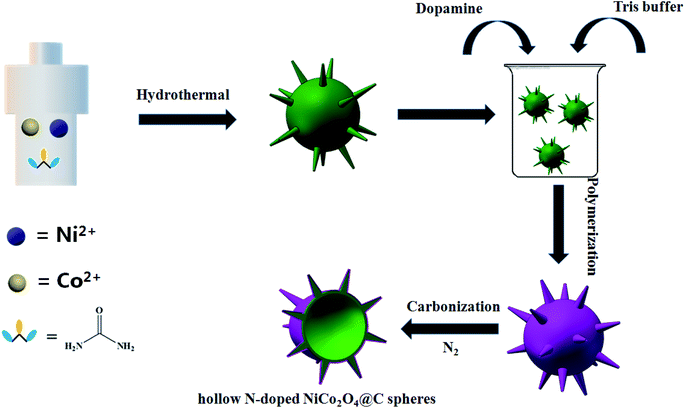
In this work, the urchin-like N-doped NiCo2O4@C hollow nanospheres have been successfully prepared, using nickel–cobalt oxide nanoparticles as templates, dopamine as carbon and nitrogen sources, and applied to high performance supercapacitors (Scheme 1). In a three-electrode cell, the resultant material exhibited an admirable specific capacitance of 1028 F g−1 at a current density of 3 A g−1, with 625 F g−1 remaining even at high current density of 20 A g−1. The electrochemical properties have been greatly improved compared with those reported that hollow nickel–cobalt oxides synthesized by using polydopamine spheres as templates. Therefore, the improvement of electrochemical performance is ascribed to the combination of co-doping of nitrogen and carbon heteroatoms.40 It has great application potential in energy storage materials.
2. Experimental section
2.1 Synthesis of nickel–cobalt hydroxide precursors
All reagents are analytical grade without further purification. Firstly, 34.0 ml of deionized water and 6.0 ml of anhydrous ethanol were mixed in a beaker and stirred evenly. Then 0.874 g of Ni(NO3)2·6H2O and 0.872 g of Co(NO3)2·6H2O were added to the beaker respectively. After continuous stirring, 1.44 g urea was inserted into the above prepared mixed solution, and 5000 rpm magnetic stirring for 20 min. The resulting solution was transferred to a 100 ml Teflon-lined stainless steel autoclave and heated at 120 °C for 12 hours in an oven. Finally, the brown precipitates were obtained by centrifuging for 6000 rpm with deionized water several times and drying overnight at 70 °C.2.2 Preparation of N-doped NiCo2O4@C and NiCo2O4
The N-doped NiCo2O4@C and NiCo2O4 materials were achieved by employing an easy and facile pyrolysis method. Briefly, the dopamine hydrochloride (5 mM) was dispersed in 100 ml Tris–HCl buffer solution, stirred by magnetic for 5 min, and 0.5 g of Ni(OH)2/Co(OH)2 hydroxide precursor was added into the above solution, magnetically stirred at room temperature for 12 hours, and the black precipitates were collected. NiCo2O4 sample was synthesized by the same method without the addition of dopamine hydrochloride. The precipitates were collected by centrifuging for 6000 rpm with deionized water as well as ethanol solution, then dried at 80 °C overnight. Finally, the N-doped NiCo2O4@C and NiCo2O4 compound materials were obtained by annealing at 300 °C for 3 hours in a tubular furnace at a heating rate of 2 °C min−1 in N2 atmosphere.2.3 Materials characterization
The morphological of all samples was observed by a Supra 55 scanning electron microscopy (SEM). The X-ray diffraction (XRD) patterns were recorded by a D/max 2500 PC diffractometer with a Cu Kα radiation (wavelength = 1.54056 Å, Rigaku, Japan) at room temperature. The microscopic features were executed using transmission electron microscope (TEM, JEOL 2100F) at 200 kV. Raman spectroscopy was conducted by using a JY-HR800 micro-Raman spectrometer with a × 50 objective and 532 nm excitation light emitted from a He–Ne laser. Nitrogen adsorption–desorption isotherms of the samples was performed with nitrogen cryosorption Micromeritics QuadraSorb Station 1, and the surface area was measured by Brunauer–Emmett–Teller (BET) method.2.4 Electrochemical measurements
All electrochemical measurements were carried out in a three-electrode cell configuration with CHI660E electrochemical workstation (Shanghai Chenhua Instruments Limited, China). A piece of platinum foil was employed as the counter electrode and saturated calomel electrode (SCE) was invoked as the reference electrode. The working electrode was prepared by mixing N-doped NiCo2O4@C and NiCo2O4 active electrode materials with polytetrafluoroethylene (PTFE) and acetylene black according to a mass ratio of 8![[thin space (1/6-em)]](https://www.rsc.org/images/entities/char_2009.gif) :
:![[thin space (1/6-em)]](https://www.rsc.org/images/entities/char_2009.gif) 1
1![[thin space (1/6-em)]](https://www.rsc.org/images/entities/char_2009.gif) :
:![[thin space (1/6-em)]](https://www.rsc.org/images/entities/char_2009.gif) 1 in an agate mortar. A proper amount of anhydrous ethanol is added to form a uniform slurry. The mixtures were coated on a clean nickel foam with an effective area of 1 × 1 cm2. The tablet press 10 MPa was utilized to maintain 10 s for pressing. Then the electrode was washed with ethanol and placed in a vacuum drying oven for 80 °C to dry overnight. The loading mass of active material for each electrode slice was about 3 mg, and the battery was immersed in the electrolyte for several hours before conducting electrochemical research.
1 in an agate mortar. A proper amount of anhydrous ethanol is added to form a uniform slurry. The mixtures were coated on a clean nickel foam with an effective area of 1 × 1 cm2. The tablet press 10 MPa was utilized to maintain 10 s for pressing. Then the electrode was washed with ethanol and placed in a vacuum drying oven for 80 °C to dry overnight. The loading mass of active material for each electrode slice was about 3 mg, and the battery was immersed in the electrolyte for several hours before conducting electrochemical research.
The asymmetric supercapacitors were encapsulated with N-doped NiCo2O4@C as the positive electrode and commercial activated carbon (AC) as the negative electrode. The preparation process of the counter electrode was the same as that of the active material electrode. The electrode and separator were cut to suitable size and sealed in the button of CR2032 with a 3 M KOH electrolyte. It is worth noting that the separator should be immersed in the electrolyte for one night before assembly.
In a three electrode system, the specific capacitance of the electrode materials were obtained by the following equations:
 | (1) |
3. Results and discussion
3.1 Characterization of synthesized products
Scanning electron microscope (SEM) photographs of as-synthesized Ni(OH)2/Co(OH)2, NiCo2O4 and N-doped NiCo2O4@C samples with different magnifications were investigated in Fig. 1. Detailed information relating to their size and morphology can be acquired from the images. The average sizes of Ni(OH)2/Co(OH)2, NiCo2O4 and N-doped NiCo2O4@C are 4.87, 4.20, 4.83 μm, respectively. Fig. 1(b-i) and (c-i) reveal that the annealed NiCo2O4 and N-doped NiCo2O4@C completely remain spherical structure. However, compared with Ni(OH)2/Co(OH)2, the urchin-like sphere average size decreases In Fig. 1(b-ii) and (c-ii).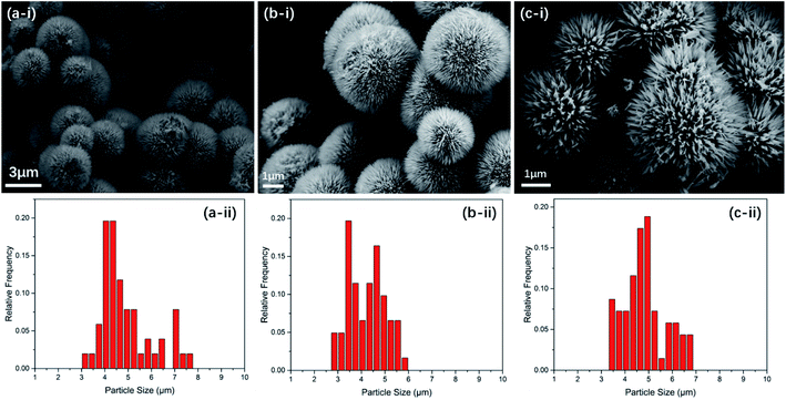 | ||
| Fig. 1 SEM images (i) and size distribution histogram (ii) of (a) Ni(OH)2/Co(OH)2, (b) NiCo2O4 and (c) N-doped NiCo2O4@C samples. | ||
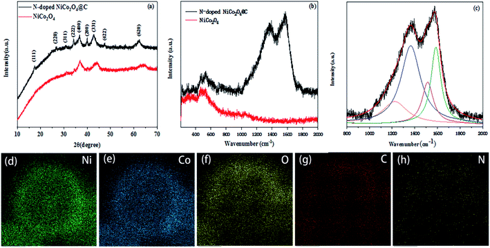
The phase composition and crystallinity of the resulting products were characterized by XRD. As shown in Fig. 2a, peaks at 2θ = 16.9°, 26.9°, 31.7°, 33.8°, 37.6°, 42.1°, 47.5° and 62.4° and their corresponding planes (111), (220), (311), (222), (400), (331), (422) and (620) were ascribed to the cubic crystal structures of NiCo2O4 (JCPDS card no. 73-1704; space group Fd3m). The peak intensity is relatively weak suggesting that the nanospheres are corresponding to small crystallite size. Peaks at 2θ = 39.7° were well indexed to the (200) planes of CoO phase (JCPDS card no. 75-0419). The above results corroborate that the presence of CoO impurities in the prepared N-doped NiCo2O4@C composites.
As shown in the Fig. 2b, the Raman spectrum of N-doped NiCo2O4@C exhibits sharp scattering peaks at 1365 and 1580 cm−1 relative to NiCo2O4 samples, which designate as characteristic D band and G band of carbon materials.41 It is well known that the D band is related to the vibrations of disordered carbon or the defects of carbon atom lattice, whereas the G band stems from characteristic of the in-plane stretching vibration of sp2 hybridization. In Fig. 2c, the strength ratio of the D band and G band (ID/IG) is 1.9 by Origin Software fitting (Lorentzian Multi-peaks). High intensity ratio reveals abundant structural disorders and defects, which can provide more active sites for metal ions adsorption, so it is favorable to improving the conductivity of composites.42 The EDS elemental mapping of the N-doped NiCo2O4@C was detected in Fig. 2d–h, which further confirmed the uniform distribution of carbon and nitrogen in the whole sphere.
Fig. 3a and b display the TEM images of NiCo2O4 and N-doped NiCo2O4@C, respectively. It is verified that the hollow structure of the coated carbon material containing nitrogen is completely preserved. Fig. 3c further shows that nanowires with needle tips self-assembled together to form urchin-like hollow microspheres, which are then uniformly covered with polydopamine and converted into N-doped carbon after annealing treatment. This structure is beneficial to the diffusion of ions and provides sufficient active sites for the faradaic reactions, thus stimulating higher specific capacitance.43 From the HRTEM photographs in Fig. 3d–f, it can be intuitively observed that the crystalline N-doped NiCo2O4@C nanoparticles are surrounded by amorphous N-doped carbon shells, which further prove that the nitrogen-containing carbon material is successfully coated on the surface of the sample. The thickness of the coating is from 3 to 10 nm. Besides, we can accurately control the thickness of the sample covering by regulating the concentration and reaction time of dopamine. The lattice fringes of nanowires demonstrate interplanar distances of 0.21, 0.23 and 0.26 nm, indexing to (400) and (331) and (422) plane of the spinel structured NiCo2O4, respectively.
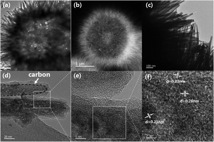 | ||
| Fig. 3 (a and b) TEM images of NiCo2O4 and N-doped NiCo2O4@C; (c–e) TEM images of N-doped NiCo2O4@C nanowires; (f) the corresponding HRTEM image of the N-doped NiCo2O4@C nanowire. | ||
Fig. 4 reveals the chemical composition of N-doped NiCo2O4@C by XPS spectra. The elements Ni, Co, C, O and N are obviously observed in the detailed XPS survey spectrum (Fig. 4a). The contents of Ni, Co, C, O and N in N-doped NiCo2O4@C are 11.24, 10.81, 51.78, 23.37 and 2.80%, respectively. Herein, we adopt a Gaussian fitting method to fit and analyze the oxidation state of the constituent elements. High resolution of Co 2p spectra is illustrated in Fig. 4b. It is not difficult to find a pair of main fitting peaks at binding energies of 780.2 and 796.1 eV, which are ascribed to Co2+. The other two fitting peaks are at 781.8 and 797.8 eV, respectively, corresponding to Co3+.44,45 As shown in Fig. 4c, sharp Ni2+ and Ni3+ peaks are detected in the emission spectra of Ni 2p. Fitting peaks of 855.1 eV and 872.6 eV are related to Ni2+. In addition, fitting peaks of 856.6 eV and 874.4 eV are assigned to Ni3+. In Fig. 4d, the peak at 529.62 eV is assigned to the characteristic peak of metal oxygen bond, while the peak at 531.52 eV belongs to hydroxyl or chemisorbed oxygen, and the other peak is 533.18 eV, representing surface or chemisorbed water.46,47 It must be pointed out that the peak intensity of 531.52 eV is the highest, which proves that there are many defects in the prepared composite structure. The XPS spectrum of C 1s (Fig. 4e) is fitted by three peaks at 284.78, 286.20 and 288.65 eV, corresponding to C–C, C–N, and –COO bonds, respectively. N 1s spectrum (Fig. 4f) is divided into three peaks at 398.58, 399.86 and 400.85 eV, which can be allotted to pyridinic-N, pyrrolic-N and quaternary-N.48,49 The above results show that transition metals have mixed valence states, which can provide more chemical adsorption sites for reversible adsorption of oxygen. This will further bring about the electronic transition of cations with different valence states, thus significantly improving the electrical conductivity of the electrode materials.45
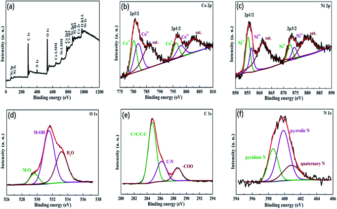 | ||
| Fig. 4 (a) XPS full survey spectra of N-doped NiCo2O4@C sample; their corresponding high resolution spectra of (b) Co 2p, (c) Ni 2p, (d) O 1s, (e) C 1s and (f) N 1s. | ||
3.2 Electrochemical properties of the NiCo2O4 and N-doped NiCo2O4@C electrodes
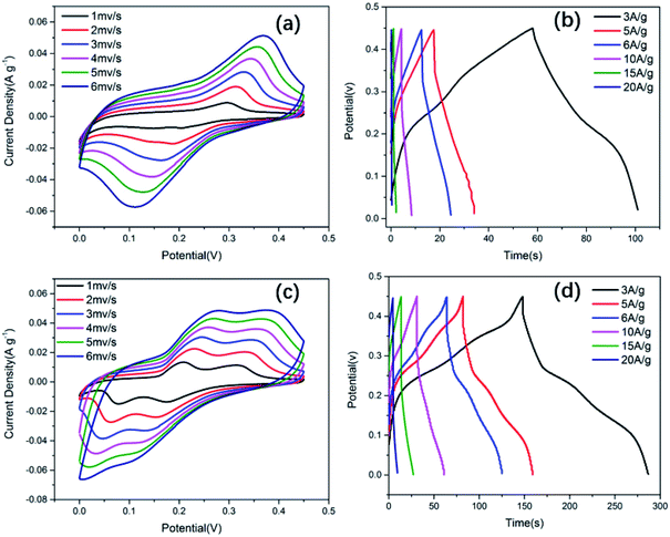
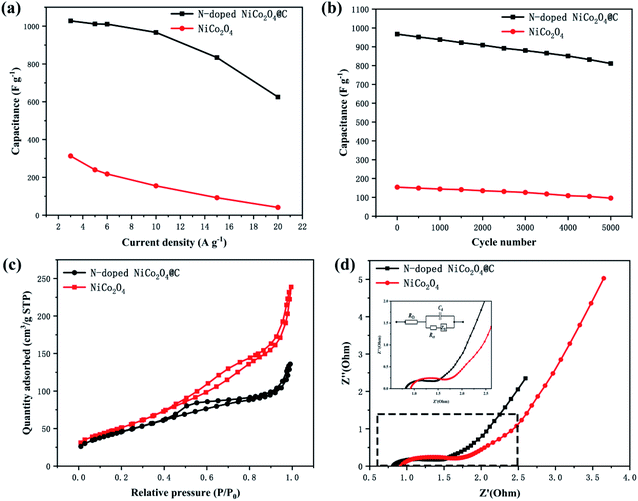
All electrochemical tests were performed in a three-electrode electrochemical cell system. The N-doped NiCo2O4@C and NiCo2O4 electrodes were studied in 2.0 M KOH aqueous electrolytes. In order to maintain the performance of the electrode stable, the potential window was 0–0.45 V, while the saturated calomel electrode (SCE) was selected as the reference electrode. Fig. 5a and c show the CV curves of NiCo2O4 and N-doped NiCo2O4@C hollow nanosphere electrodes. With the increase of scanning rate, the integral area of CV increases gradually at different scanning rates. Clear redox peaks can be achieved from the curves, which indicated that the capacitive properties depended on the Faraday reaction of MO/MO–OH, in which M represents Co–Ni ions.In addition, with the increase of scanning rate, the reductive peak in the CV curve shifts to a more negative potential, while the oxidative peak shifts to a higher positive potential. This result is ascribed to an increasing internal diffusion resistance and polarization of the electrode materials.50 The specific capacitance of N-doped NiCo2O4@C nanostructured electrode material can be calculated by galvanostatic charge–discharge (GCD) curve. It is not difficult to find that GCD curve provides a perfect platform for redox process in Fig. 5d. The specific capacitance of the as-synthesized N-doped NiCo2O4@C electrode is 1028, 1012, 1004, 967, 834, 625 F g−1 at different current densities ranging from 3 to 20 A g−1, which is consistent with the above CV analysis. High current density hinders proton diffusion, which results in inadequate participation of active materials in reversible redox reactions. Therefore, the specific capacitance decreases significantly with the increase of current density. Nevertheless, their specific capacities for the NiCo2O4 at 3, 5, 6, 10, 15, 20 A g−1 are 313, 240, 218, 155, 92, 41 F g−1, respectively. Compared with NiCo2O4, the existence of N-doped carbon layer not only accelerates the charge transfer at the interface between electrodes and electrolytes, but also increases the separation between the crystal structures of NiCo2O4, which promotes the electrolyte to move to the active surface.51 Thus, the introduction of dopamine into transition metal oxides to generate N-doped carbon layers is of great help to improve the electrochemical properties of the composites.
In Fig. 6b, the cycling stability of N-doped NiCo2O4@C electrode was evaluated at a current density of 10 A g−1. After 5000 charge–discharge cycles, the specific capacity retention rate of N-doped NiCo2O4@C electrode remained 84%, which was superior to 62% of NiCo2O4 electrode. In order to analyze the BET specific surface areas of the as-synthesized products of N-doped NiCo2O4@C and NiCo2O4, the N2 adsorption–desorption isotherm curve was implemented as shown in Fig. 6c. The BET specific surface area of N-doped NiCo2O4@C is 166.8 m2 g−1, which is less than 181.0 m2 g−1 of NiCo2O4. However, the specific capacitance of N-doped NiCo2O4@C electrode material is more than three times that of NiCo2O4. These results reveal that N-doped NiCo2O4@C possesses more electrochemical active sites than NiCo2O4.
The electrochemical impedance spectroscopy (EIS) analysis was used to investigate the conductivity and capacitance characteristics of the electrode materials in the frequency range from 0.1 to 10 MHz at a voltage amplitude of 10 mV. Fig. 6d shows N-doped NiCo2O4@C and NiCo2O4 the Nyquist plots of the electrodes, which were governed by both electron transfer and diffusion processes. The equivalent circuits of the electrochemical system were fitted in the illustration. In the whole frequency range, the Nyquist diagram consists of a semicircle in the high frequency region and a 45° inclined line in the low frequency region. The high frequency region is controlled by the kinetics of the electrode reaction, while the low frequency region is regulated by the diffusion of the reactants or products of the electrode reaction. In the high frequency region, the curve deviates from the semicircular trajectory and shows a circular arc. This dispersion effect is ascribed to the inhomogeneity of the surface of the electrode and the poor conductivity of the solution. Fig. 6d shows a partial enlargement of the Nyquist plot. Compared with NiCo2O4, the composite N-doped NiCo2O4@C possesses shorter semicircle diameter and higher vertical slope, which demonstrates that the N-doped NiCo2O4@C electrode material exhibits lower equivalent series resistance and higher electric conductivity.52 The introduction of nitrogen doped carbon layer is attributed to the decomposition of dopamine, which combines carbon based materials with high conductivity and NiCo2O4 as a single electrode. It is possible that the polarization of the interface can significantly improve the attractors and intercalations of electrolyte ions, resulting in a better charge transfer dynamics.53 The above results indicate that the superior capacitive behavior of transition metal oxide composites may be attributed to the N-doped carbon materials on the surface of nickel cobalt oxide nanospheres.
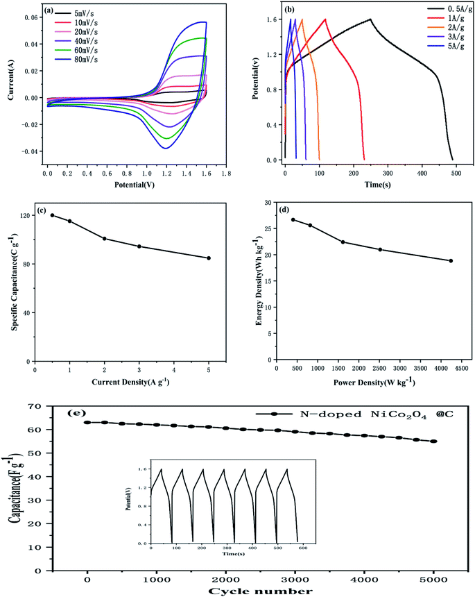
In order to further evaluate the practical application prospects of the prepared electrode materials, the N-doped NiCo2O4@C//AC asymmetric supercapacitor was investigated. The mass of the activated carbon electrode must satisfy the following formula to ensure the same amount of charge through the positive and negative electrodes:54
| m− × (Cg− × ΔV−) = m+ × (Cg+ × ΔV+) | (2) |
 | (3) |
 | (4) |
4. Conclusions
In summary, a facile strategy has been developed to prepare uniform urchin-like N-doped NiCo2O4@C hollow nanocomposites on nickel–cobalt hydroxide substrates by dopamine polymerization followed by annealing. Compared with NiCo2O4, the excellent electrochemical properties of N-doped NiCo2O4@C are attributed to the following unique factors. Firstly, due to the synergistic effect of Ni and Co, binary nickel–cobalt oxide (NiCo2O4) electrode materials possess a superior theoretical specific capacitance; secondly, the introduction of carbon material increases the active site for the redox reaction and improves the conductivity of the electrode materials; thirdly, the combination of nitrogen element leads to the introduction of additional pseudocapacitance. Therefore, these results confirm that the N-doped NiCo2O4@C materials have great application prospects in high performance supercapacitors.Conflicts of interest
The authors declare no competing conflict of interest.Acknowledgements
This research did not receive any specific grant from funding agencies in the public, commercial, or not-for-profit sectors.References
- Y. Jin, Y. Meng, W. Fan, H. Lu, T. Liu and S. Wu, Electrochim. Acta, 2019, 318, 865–874 CrossRef CAS.
- Y. Zhai, Y. Dou, D. Zhao, P. F. Fulvio, R. T. Mayes and S. Dai, Adv. Mater., 2011, 23, 4828–4850 CrossRef CAS PubMed.
- G. Xu, J. Han, B. Ding, P. Nie, J. Pan, H. Dou, H. Li and X. Zhang, Green Chem., 2015, 17, 1668–1674 RSC.
- Q. Liang, L. Ye, Z. H. Huang, Q. Xu, Y. Bai, F. Kang and Q. H. Yang, Nanoscale, 2014, 6, 13831–13837 RSC.
- G. Meng, Q. Yang, X. Wu, P. Wan, Y. Li, X. Lei, X. Sun and J. Liu, Nano Energy, 2016, 30, 831–839 CrossRef CAS.
- C. Liu, C. Zhang, H. Song, X. Nan, H. Fu and G. Cao, J. Mater. Chem. A, 2016, 4, 3362–3370 RSC.
- L. F. Chen, Z. Y. Yu, X. Ma, Z. Y. Li and S. H. Yu, Nano Energy, 2014, 9, 345–354 CrossRef CAS.
- J. Tian, Y. Xue, M. Wang, Y. Pei, H. Zhang and J. Wang, Electrochim. Acta, 2019, 296, 49–58 CrossRef CAS.
- Y. Tang, Y. Liu, S. Yu, Y. Zhao, S. Mu and F. Gao, Electrochim. Acta, 2014, 123, 158–166 CrossRef CAS.
- Y. Ren and L. Gao, J. Am. Ceram. Soc., 2010, 93, 3560–3564 CrossRef CAS.
- Y. Lv, H. Wang, X. Xu, J. Shi, W. Liu and X. Wang, Chem. Eng. J., 2017, 326, 401–410 CrossRef CAS.
- G. Gao, H. B. Wu, S. Ding, L. M. Liu and X. W. Lou, Small, 2015, 11, 804–808 CrossRef CAS.
- M. Sethi and D. K. Bhat, J. Alloys Compd., 2019, 781, 1013–1020 CrossRef CAS.
- K. Dong, Z. Wang, M. Sun, D. Wang, S. Luo and Y. Liu, J. Alloys Compd., 2019, 783, 1–9 CrossRef CAS.
- V. Veeramani, R. Madhu, S. M. Chen and M. Sivakumar, ACS Sustainable Chem. Eng., 2016, 4, 5013–5020 CrossRef CAS.
- C. Yuan, X. Zhang, L. Su, B. Gao and L. Shen, J. Mater. Chem., 2009, 19, 5772 RSC.
- S. Xiong, C. Yuan, X. Zhang, B. Xi and Y. Qian, Chemistry, 2009, 15, 5320–5326 CrossRef CAS.
- X. H. Xia, J. P. Tu, Y. J. Mai, X. L. Wang, C. D. Gu and X. D. Zhao, J. Mater. Chem., 2011, 21, 9319 RSC.
- Y. Tang, Z. Liu, W. Guo, T. Chen, Y. Qiao, S. Mu, Y. Zhao and F. Gao, Electrochim. Acta, 2016, 190, 118–125 CrossRef CAS.
- X. Qi, W. Zheng, G. He, T. Tian, N. Du and L. Wang, Chem. Eng. J., 2017, 309, 426–434 CrossRef CAS.
- Y. Cao, B. Lin, Y. Sun, H. Yang and X. Zhang, Electrochim. Acta, 2015, 174, 41–50 CrossRef CAS.
- G. D. Park, J. S. Cho and Y. C. Kang, Nano Energy, 2015, 17, 17–26 CrossRef CAS.
- L. Chang, C. Li, H. Ouyang, J. Huang, Q. Huang and Z. Xu, Mater. Lett., 2019, 240, 21–24 CrossRef CAS.
- Y. Zhu, Y. Huang, M. Wang, K. Wang, M. Yu, X. Chen and Z. Zhang, Ceram. Int., 2018, 44, 21690–21698 CrossRef CAS.
- K. Wang, Y. Huang, M. Wang, M. Yu, Y. Zhu and J. Wu, Carbon, 2017, 125, 375–383 CrossRef CAS.
- J. Xu, F. Liu, X. Peng, J. Li, Y. Yang, D. Jin, H. Jin, X. Wang and B. Hong, ChemistrySelect, 2017, 2, 5189–5195 CrossRef CAS.
- C. Zhang, X. Geng, S. Tang, M. Deng and Y. Du, J. Mater. Chem. A, 2017, 5, 5912–5919 RSC.
- Z. S. Wu, K. Parvez, A. Winter, H. Vieker, X. Liu, S. Han, A. Turchanin, X. Feng and K. Mullen, Adv. Mater., 2014, 26, 4552–4558 CrossRef CAS.
- C. Wang, L. Sun, Y. Zhou, P. Wan, X. Zhang and J. Qiu, Carbon, 2013, 59, 537–546 CrossRef CAS.
- Y. Cheng, L. Huang, X. Xiao, B. Yao, L. Yuan, T. Li, Z. Hu, B. Wang, J. Wan and J. Zhou, Nano Energy, 2015, 15, 66–74 CrossRef CAS.
- C. Liu, J. Wang, J. Li, R. Luo, J. Shen, X. Sun, W. Han and L. Wang, ACS Appl. Mater. Interfaces, 2015, 7, 18609–18617 CrossRef CAS.
- J. Ma, J. Pan, J. Yue, Y. Xu and J. Bao, Appl. Surf. Sci., 2018, 427, 428–436 CrossRef CAS.
- Y. Liu, K. Ai and L. Lu, Chem. Rev., 2014, 114, 5057–5115 CrossRef CAS PubMed.
- J. D. Simon and D. N. Peles, Acc. Chem. Res., 2010, 43, 1452–1460 CrossRef CAS PubMed.
- W. Li, Z. Ma, G. Bai, J. Hu, X. Guo, B. Dai and X. Jia, Appl. Catal., B, 2015, 174–175, 43–48 CAS.
- T. Liu, L. Finn, M. Yu, H. Wang, T. Zhai, X. Lu, Y. Tong and Y. Li, Nano Lett., 2014, 14, 2522–2527 CrossRef CAS.
- W. Ye, Y. Chen, Y. Zhou, J. Fu, W. Wu, D. Gao, F. Zhou, C. Wang and D. Xue, Electrochim. Acta, 2014, 142, 18–24 CrossRef CAS.
- J. Si and H. Yang, Mater. Chem. Phys., 2011, 128, 519–524 CrossRef CAS.
- L. Qie, W. Chen, H. Xu, X. Xiong, Y. Jiang, F. Zou, X. Hu, Y. Xin, Z. Zhang and Y. Huang, Energy Environ. Sci., 2013, 6, 2497 RSC.
- L. F. Chen, Y. Lu, L. Yu and X. W. Lou, Energy Environ. Sci., 2017, 10, 1777–1783 RSC.
- D. Zha, Y. Fu, X. Gao, L. Zhang and X. Wang, Electrochim. Acta, 2017, 257, 494–503 CrossRef CAS.
- C. Zhang, J. Wei, L. Chen, S. Tang, M. Deng and Y. Du, Nanoscale, 2017, 9, 15423–15433 RSC.
- Y. Lu, L. Li, D. Chen and G. Shen, J. Mater. Chem. A, 2017, 5, 24981–24988 RSC.
- X. F. Lu, D. J. Wu, R. Z. Li, Q. Li, S. H. Ye, Y. X. Tong and G. R. Li, J. Mater. Chem. A, 2014, 2, 4706–4713 RSC.
- J. Yang, C. Yu, S. Liang, S. Li, H. Huang, X. Han, C. Zhao, X. Song, C. Hao, P. M. Ajayan and J. Qiu, Chem. Mater., 2016, 28, 5855–5863 CrossRef CAS.
- J. F. Marco, J. R. Gancedo, M. Gracia, J. L. Gautier, E. Ríos and F. J. Berry, J. Solid State Chem., 2000, 153, 74–81 CrossRef CAS.
- J. Liang, R. Ma, N. Iyi, Y. Ebina, K. Takada and T. Sasaki, Chem. Mater., 2010, 22, 371–378 CrossRef CAS.
- C. Wu, S. Yang, J. Cai, Q. Zhang, Y. Zhu and K. Zhang, ACS Appl. Mater. Interfaces, 2016, 8, 15288–15296 CrossRef CAS PubMed.
- X. Dong, H. Jin, R. Wang, J. Zhang, X. Feng, C. Yan, S. Chen, S. Wang, J. Wang and J. Lu, Adv. Energy Mater., 2018, 8, 1702695 CrossRef.
- J. Ji, L. L. Zhang, H. Ji, Y. Li, X. Zhao, X. Bai, X. Fan, F. Zhang and R. S. Ruoff, ACS Nano, 2013, 7, 6237–6243 CrossRef CAS PubMed.
- C. Zhang, Y. Huang, S. Tang, M. Deng and Y. Du, ACS Energy Lett., 2017, 2, 759–768 CrossRef CAS.
- L. F. Chen, Z. Y. Yu, J. J. Wang, Q. X. Li, Z. Q. Tan, Y. W. Zhu and S. H. Yu, Nano Energy, 2015, 11, 119–128 CrossRef CAS.
- C. Zhang, C. Lei, C. Cen, S. Tang, M. Deng, Y. Li and Y. Du, Electrochim. Acta, 2018, 260, 814–822 CrossRef CAS.
- Q. Liu, X. Hong, X. Zhang, W. Wang, W. Guo, X. Liu and M. Ye, Chem. Eng. J., 2019, 356, 985–993 CrossRef CAS.
| This journal is © The Royal Society of Chemistry 2019 |

