 Open Access Article
Insights into a rutile/brookite homojunction of titanium dioxide: separated reactive sites and boosted photocatalytic activity†
Jing Chena,
Meili Guan *b,
Xuan Zhangb and
Xuezhong Gongc
aSchool of Materials and Chemical Engineering, Anhui Jianzhu University, Hefei 230601, P. R. China
bInstitute for Energy Research, Jiangsu University, Zhenjiang 212013, P. R. China
cCollege of Materials Science and Engineering, National Base of International S. & T. Cooperation on Hybrid Materials and Growing Base for State Key Laboratory, Qingdao University, 308 Ningxia Road, Qingdao, 266071, P. R. China
First published on 11th November 2019
Abstract
Benefiting from studies into Degussa TiO2, forming junctions via combining different phases of a semiconductor may provide new insights into the design of efficient photocatalysts, which are a key element in current solar-driven fuel production and environmental remediation. In this work, we aimed at creating a highly efficient rutile/brookite homojunction through precise crystal phase control. Characterization of the morphology and structure revealed that the ultrafine brookite phase TiO2 particles were uniformly attached to the surfaces of the rod-like rutile phase, not only readily forming a homojunction but also stabilizing the brookite phase. Surprisingly, the rutile/brookite-TiO2 homojunction exhibited a synergetic effect, improving the photocatalytic activity for both hydrogen generation and organic dye degradation. This was attributed to the well-matched band alignment and separated reaction sites, effectively promoting the charge separation efficiency. These results highlight the potential for bifunctional photocatalyst design with separated reactive sites for simultaneous redox reactions.
Introduction
Inspired by natural photosynthesis, deriving energy and chemical fuels from sunlight and water has significant prospects and is expected to solve the severe energy and environmental problems that exist today.1 As an irreplaceable clean energy source, hydrogen can be obtained by means of semiconductor-based photocatalytic water splitting (2H2O → 2H2 + O2).2a However, when hydrogen is produced, this is not accompanied by the formation of oxygen but the production of hydrogen peroxide or other oxidation products.2b,c This directly leads to an alternative method to obtain high H2 yields: using sacrificial reagents, such as methanol, TEOA, S2−, and so on, to quench the photogenerated holes.2c–e The current problems with this approach are related to fast charge recombination within the photocatalyst and the uncertain selectivity for the oxidative products during hydrogen generation. The mechanism behind the structure related activity needs to be understood, and information is still lacking.Numerous semiconductors have been employed as catalysts for photocatalytic hydrogen generation from aqueous solutions.1 Among the various semiconductors, titanium dioxide (TiO2) deserves special attention due to its low cost, nontoxicity, thermal stability, and suitable band energies, which are well matched to the redox potentials of water.3 Although it has been demonstrated to show high photocatalytic efficiency, it is still a challenge to promote the charge separation efficiency of photogenerated electron–hole pairs, as recombination results in low hydrogen production efficiency. Improving the charge separation efficiency of TiO2 via structure construction and crystal engineering is an effective strategy to optimize the hydrogen production efficiency.
From analysis of the various TiO2-based photocatalysts, forming junctions with alien semiconductors or metals has been proven to be beneficial for enhancing the charge separation efficiency.4 It has been demonstrated that an electric field is built at the interface of the junction, and this enables photogenerated charge carriers to flow directionally across the junction, thus inhibiting the charge recombination process.5 A prerequisite for forming an effective heterojunction is that the two semiconductors have well-matched band positions. A homojunction, which is composed of two different phases but with the same composition, guarantees the continuity of the band alignment and thus provides feasible options for inhibiting the charge recombination process without introducing alien elements. Hence, designing and constructing homojunctions has received a lot of research interest in terms of the low-cost production of highly efficient photocatalysts.
Generally speaking, rutile, anatase, and brookite are the three main phases of TiO2. The crystal structures of the three phases are all based upon TiO6 octahedra, with rutile and brookite consisting of both corner- and edge-sharing frameworks.6 One of the examples of a homojunction within TiO2 is commercial Degussa P25, which consists of anatase (79%) and rutile (21%) phases. Theoretical and experimental studies on its outstanding photocatalytic activity have revealed that it is the junction boundaries between the anatase and rutile phases that play a key role in improving the charge separation efficiency.7 Inspired by this but moving beyond it, forming a homojunction via combining two of the three phases is expected to generate fantastic properties. Theoretical calculations and experiments have shown that both rutile-TiO2 and brookite-TiO2 are direct bandgap semiconductors, but the charge separation efficiencies of the pure phases are severely inhibited. The challenging synthesis of brookite TiO2 makes studies of rutile–brookite homojunctions rare. To extend the versatilities of homojunctions and explore efficient photocatalysts, it is highly desirable to fabricate and optimize a rutile–brookite junction via tuning the integration of the two phases, so as to enhance the charge separation efficiency.
In this work, TiO2 with a rutile/brookite homojunction was synthesized via a facile solvothermal method. Characterization of the homojunction morphology reveals that ultrafine brookite particles are anchored on rod-like rutile phase TiO2. Such a configuration improved the stability of the rutile/brookite homojunction. Photocatalysis assessments show that the rutile/brookite-TiO2 homojunction exhibits excellent photocatalytic activities for hydrogen generation and the degradation of RhB organic dye under solar irradiation in comparison with pure rutile and brookite phases. The boosted photocatalytic activity came from the formation of the homojunction, which led to the charge separation efficiency being promoted. Finally, an understanding of the enhancement mechanism of the homojunction was prudently sought and the prospect of obtaining hydrogen fuel from wastewater and solar light in practice was highlighted.
Experimental
Synthesis of the rutile/brookite-TiO2 homojunction
To obtain the rutile/brookite-TiO2 sample, 2.15 mL of titanium tetrachloride (TiCl4) was added into 8.6 mL of deionized water dropwise at 4 °C. After stirring for a while, 3.23 mL of triethylamine was dissolved into the above solution. The total volume of the mixture was set to 65% of the Teflon vessel capacity through adding additional DI water. Afterward, the solution was transferred to a 50 mL Teflon-lined stainless-steel autoclave and placed in an oven at 150 °C for 24 h. After being cooled down to room temperature naturally, the final precipitate was collected via centrifugation and washed with deionized water and alcohol, followed by drying in the oven at 60 °C for 12 h.To obtain pure rutile-TiO2 and brookite-TiO2, the procedures were the same as given above, except that the triethylamine volumes were adjusted to 2.15 mL and 19.4 mL, respectively.
Characterization
The X-ray diffraction (XRD) patterns were recorded with a Philips X'Pert Pro Super diffractometer using Cu-Kα radiation (λ = 1.54178 Å). Raman spectra were obtained using a LABRAM-HR confocal laser micro Raman spectrometer at room temperature. The transmission electron microscopy (TEM) images were taken using a H-7650 microscope (Hitachi, Japan) operated at an acceleration voltage of 100 kV. High-resolution transmission electron microscopy (HRTEM) images were obtained using JEM-ARM200F apparatus at an acceleration voltage of 200 kV. X-ray photoelectron spectroscopy (XPS) measurements were carried out using a VG ESCALAB MK II X-ray photoelectron spectrometer with a Mg Kα excitation source (1253.6 eV). UV-vis absorption spectra were recorded using a PerkinElmer Lambda 950 UV-vis-NIR spectrophotometer. Flat band potentials were measured in the dark at a frequency of 10 Hz under applied potentials from −1.4 V to +0.5 V.Photocatalytic measurements
Photocatalytic hydrogen evolution tests were conducted in a closed system equipped with a Pyrex glass reactor, gas circulation and vacuum pumps, and a 300 W xenon lamp that was used as the light source. First of all, 50 mg of sample was dispersed in 200 mL of aqueous methanol solution (MeOH/H2O 1![[thin space (1/6-em)]](https://www.rsc.org/images/entities/char_2009.gif) :
:![[thin space (1/6-em)]](https://www.rsc.org/images/entities/char_2009.gif) 4 v/v). Then, the system was placed under vacuum to remove residual air. During irradiation, the produced hydrogen was withdrawn automatically at different times from the headspace and was analyzed quantitatively online with a gas chromatograph (Agilent 7890A) equipped with a TCD.
4 v/v). Then, the system was placed under vacuum to remove residual air. During irradiation, the produced hydrogen was withdrawn automatically at different times from the headspace and was analyzed quantitatively online with a gas chromatograph (Agilent 7890A) equipped with a TCD.
For the photodegradation of RhB, 5 mg of sample was dispersed into 50 mL of RhB solution (1 × 10⁻⁵ M). Before being illuminated under the 300 W xenon lamp, the suspension was kept under stirring for 2 h to establish adsorption–desorption equilibrium. 5 mL of suspension was taken out every 30 min, followed by centrifugal separation to obtain supernatant solution for UV-vis spectroscopy analysis. The degradation process of RhB can be monitored through the changing of its characteristic absorption, and the dynamic concentration can be represented using the normalized absorbance intensity at 554 nm.
Results and discussion
Characterization of the crystal structure and morphology
The crystal structures of the prepared samples were firstly characterized via X-ray diffraction, and the XRD patterns are displayed in Fig. 1a. The major diffraction peaks at 2θ values of 27.3°, 36.1°, 41.2° and 54.1° are ascribed to the (110), (101), (111), and (211) facets of rutile phase TiO2 (tetragonal, JCPDS no. 87-0710, a = b = 4.58 Å, c = 2.95 Å, α = β = γ= 90°). The peaks at 2θ values of 25.4°, 30.7° and 48.1° are attributed to the (120), (121) and (231) facets of the brookite phase of TiO2 (orthorhombic, JCPDS no. 29-1360, a = 5.456 Å, b = 9.182 Å, c = 5.143 Å, α = β = γ= 90°). No peaks from an anatase phase were observed.8 These results showed that the rutile/brookite TiO2 sample had only rutile and brookite phases. The rutile phase is the major component in the rutile/brookite-TiO2 sample, judging from the relative peak intensities.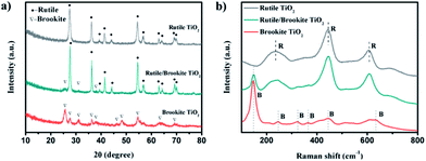 | ||
| Fig. 1 (a) XRD patterns and (b) Raman spectra of rutile-TiO2, rutile/brookite-TiO2 and brookite-TiO2 samples. | ||
Given the crystal structure obtained from XRD analysis, the different phases of TiO2 were further identified via Raman spectroscopy. Raman spectroscopy (Fig. 1b) displays a rutile phase (space group: D144h) with three active modes at 235 cm−1 (B1g), 444 cm−1 (Eg), and 612 cm−1 (A1g), in good agreement with previous reports.9 Brookite (space group: D152h) is characterized by a strong peak at 148 cm−1 and exhibited a relatively complex vibrational spectrum, consistent with the unit cell symmetric D2h and site symmetric C1 modes of both Ti and O.10 The existence of peaks from the rutile and brookite spectra in the rutile/brookite-TiO2 spectrum indicates that both phases coexist in the sample.
The morphologies of rutile-TiO2 and brookite-TiO2 and the junction features of rutile/brookite-TiO2 were characterized via TEM, as shown in Fig. 2. Rutile-TiO2 possessed rod-like morphology with lengths of 150–200 nm (Fig. 2a), while the brookite-TiO2 was shown to be in the form of ultrafine nanoparticles (Fig. 2b). TEM images of rutile/brookite-TiO2 (Fig. 2c and d) show that the rod-like rutile-TiO2 particles were decorated with ultrafine brookite-TiO2 nanoparticles. A previous report has concluded that brookite is thermodynamically stable only at sizes between 11 and 35 nm.11 However, in this work the stability of the ultrafine brookite nanoparticles (∼5 nm) seems to rely on them being anchored onto the rod-like rutile phase in a semi-embedded way.
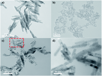 | ||
| Fig. 2 TEM images of (a) rutile-TiO2 and (b) brookite-TiO2. A TEM image of (c) rutile/brookite-TiO2 and (d) a magnified image from the region in the dashed box. | ||
HRTEM images provide more information for identifying the junction; as shown in Fig. 3a, the clear crystal lattices in the image indicate the good crystallinity of TiO2 prepared through this method. Magnified images of the selected regions (as labeled in red rectangles) are shown in Fig. 3b and c. The measured lattice fringes of 0.25 nm correspond to the d-spacing of the (101) planes of rutile TiO2, while the lattice fringes with a spacing of 0.21 nm correspond to the d-spacing of the (221) planes of brookite TiO2. This confirms that both rutile and brookite phases coexist in the synthesized rutile/brookite TiO2. Hence, HRTEM, TEM, Raman and XRD analysis together proved that a rutile/brookite TiO2 homojunction was successfully prepared.
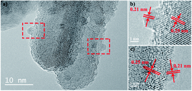 | ||
| Fig. 3 HRTEM images of (a) rutile/brookite-TiO2 and (b and c) the selected areas in the dashed boxes with labeled lattice fringes. | ||
Photocatalytic activity assessment
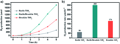
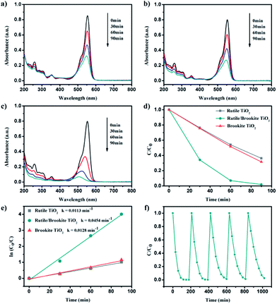
The photocatalytic activity for hydrogen production over the synthesized rutile/brookite-TiO2 was evaluated in comparison with pure rutile phase and brookite phase TiO2. Fig. 4a shows the amount of H2 evolved over the samples within 5 h. The H2 evolution rates were calculated and are shown in Fig. 4b. A 3-fold enhancement in the hydrogen evolution rate could be measured for brookite-TiO2 (176 μmol h−1) compared with rutile-TiO2 (58 μmol h−1). This may be due to the relative negative conduction band position of brookite-TiO2 (which is discussed below). The hydrogen evolution rate over rutile/brookite-TiO2 reached 368 μmol h−1, enhancements of more than 6-fold and 2-fold compared to rutile-TiO2 and brookite-TiO2, respectively. The improved photocatalytic activity for H2 generation can be ascribed to a synergetic effect, which arises from the intimate contact at the rutile–brookite phase junction rather than simple physical mixing of the two phases.To further confirm the synergetic effect of the homojunction, the photocatalytic degradation of RhB was carried out. Fig. 5a–c depicts the dynamic changes in the absorption spectra of RhB over the samples during continuous light irradiation. The corresponding RhB concentration change time profiles were determined from the characteristic absorption peak at 554 nm, and are shown in Fig. 5d. The degradation rates could be described via pseudo-first-order kinetics (Fig. 5e). There was only a slight difference in the degradation rates over rutile-TiO2 (0.0113 min−1) and brookite-TiO2 (0.0128 min−1). However, a 4-fold enhancement in the degradation rate of RhB could be measured for rutile/brookite-TiO2 (0.0454 min−1) compared with rutile-TiO2. This could be attributed to effective interfacial charge transfer across the homojunction, leading to enhanced charge carrier lifetimes and separation.12 Given that the degradation rate over rutile/brookite-TiO2 was higher than the simple addition of the rates over rutile-TiO2 and brookite-TiO2, the superior photocatalytic degradation efficiency is essentially dictated by the synergetic effect from the homojunction.13 The stability of rutile/brookite-TiO2 was evaluated via the repeated photocatalytic degradation of RhB, as shown in Fig. 5f. RhB was almost completely decomposed during each cycle, and there was no obvious decrease in the photocatalytic activity after 5 cycles. In other words, rutile/brookite-TiO2 showed great potential to be utilized as an efficient and stable photocatalyst for practical applications.
Band alignment of the homojunction
To account for the mechanism explaining how the homojunction enhances the photocatalytic activity, the band structure of rutile-/brookite-TiO2 was investigated. First of all, the optical properties of rutile-TiO2, brookite-TiO2, and rutile/brookite-TiO2 were studied via UV-vis absorption spectroscopy and the corresponding diffuse reflectance spectra, obtained via the Kubelka–Munk function, as shown in Fig. 6a and b. The absorption edges of rutile- and brookite-TiO2 appear at ∼415 and ∼411 nm, corresponding to band energies of ∼3.05 and 3.15 eV, respectively. This is consistent with the density of states (DOS) results, as shown in Fig. S1.† For the rutile/brookite homojunction, similar absorption bands to those of rutile-TiO2 were observed, which can be attributed to the predominance of the rutile phase in the homojunction. This is consistent with the observations from the XRD results and TEM images. To provide the absolute band-edge positions of rutile-TiO2 and brookite-TiO2, XPS valence band spectra were provided to measure the VB band-edge positions, as shown in Fig. 6c. The VB maxima of rutile-TiO2 and brookite-TiO2 were estimated to be +2.81 eV and +2.45 eV, respectively. Correspondingly, the CB band-edge potentials were calculated to be −0.24 eV and −0.7 eV, according to the relationship ECB = EVB − Eg. The band alignments of the rutile/brookite homojunction satisfy the necessary requirements for the photocatalytic reduction of protons to produce hydrogen and for the photocatalytic oxidation of organic dyes.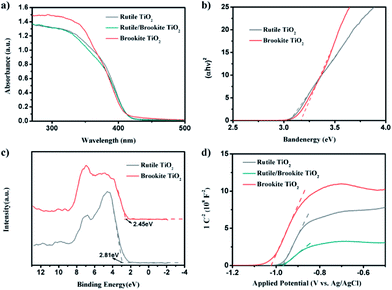 | ||
| Fig. 6 (a) UV-vis absorption spectra and (b) the corresponding diffuse reflectance spectra obtained via the Kubelka–Munk function. (c) XPS valence-band spectra and (d) Mott–Schottky plots. | ||
Mott–Schottky analysis offers more information about semiconductor behavior. The carrier densities and flat band potentials can be estimated using the following eqn (1):
 | (1) |
The Mott–Schottky plots make clear that all the samples are n-type semiconductors, as the linear plots have positive slopes. The flat band potentials were calculated from the intercept obtained via extrapolating the linear part to the x-axis in Fig. 6d. These calculations showed that Efb was approximately −0.36 V vs. NHE (pH = 0) for rutile and −0.41 V vs. NHE (pH = 0) for brookite, respectively, after correcting for the pH of the solution. These results were in good agreement with the CB band positions calculated above; for n-type semiconductors, the flat band potential is normally 0.1–0.3 eV higher than the conduction band (CB) potential.15 The flat band potential for rutile/brookite-TiO2 was calculated to be −0.36 V vs. NHE (pH = 0), which was close to the rutile value, indicating the formation of a homojunction, rather than a physical mixture of rutile and brookite phases. The donor density (ND) could be calculated from the following eqn (2):
 | (2) |
The donor density was inversely proportional to the value of the slope. Therefore, rutile/brookite-TiO2, with the lowest slope value, has the highest donor density of the three samples. Therefore, the homojunction and the higher donor density of rutile/brookite-TiO2 resulted in superior photocatalytic activity compared to rutile-TiO2 and brookite-TiO2.
Mechanism exploration
It is commonly accepted that the surface area of a photocatalyst plays an important role in its catalytic activity. The nitrogen adsorption–desorption isotherms and Barrett–Joyner–Halenda (BJH) pore size distributions of the samples are shown in Fig. 7. Nitrogen isotherm analysis shows type IV isotherms, which are typical of mesoporous materials with H3-type hysteresis. The BET surface area and BJH pore diameter data are summarized in Table S1.† After normalization according to the specific surface area, the H2 generation rate over rutile/brookite-TiO2 is still the highest, about 6 times the value over rutile-TiO2 and 3 times the value over brookite-TiO2.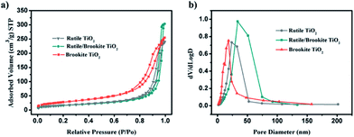 | ||
| Fig. 7 (a) Nitrogen adsorption isotherms from the samples; and (b) the pore size distributions of the samples. | ||
It has been reported that the anisotropic 1D nature of the brookite nanorods results in improved charge separation efficiency, leading to higher H2 generation rates and quantum efficiencies.16a In this work, the special configuration of brookite dots/rutile rods and the well-matched band alignments allow for the separated electrons and holes to flow across the junction to the brookite dots and rutile rods, respectively. As investigated by Fornasiero's group, the carrier trap-related photocatalytic activity over TiO2 polymorphs cannot be neglected. It is found that brookite exhibits shallow charge trapping and longer charge carrier lifetimes, which is promising for the photocatalytic oxidation of water.16b However, rutile demonstrates deeper charge trapping, while the presence of the junction inhibited charge recombination. Hence the junction within rutile/brookite-TiO2 played a significant role in promoting the charge separation efficiency, thus improving the H2 generation efficiency.
Given the above findings and discussion, a concise photocatalytic mechanism can be presented, as shown in Fig. 8. Upon irradiation, photogenerated electrons and holes were localized at the CBs and VBs of both the rutile phase and brookite phase. The formed homojunction at the interface provides an electric driving force to direct photoelectrons flowing from the brookite phase to the rutile phase, and the process is reversed for the photogenerated holes. Thus, charge recombination was inhibited while charge separation was improved by the junction. The reduction reaction takes place at the rutile phase, where more net photoelectrons accumulated and were consumed by protons. The photo-oxidation reaction, however, mainly happens at the brookite phase, where photogenerated holes are capable of oxidizing water to form hydroxyl radicals, which act as reactive species for organic dye degradation. Therefore, TiO2 with a rutile/brookite homojunction possesses great potential to act as a bifunctional photocatalyst for simultaneous photocatalytic reduction and oxidation reactions.
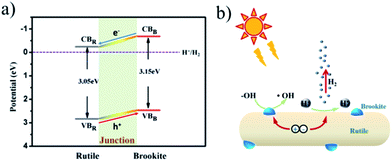 | ||
| Fig. 8 (a) The band structures of rutile and brookite, and (b) a schematic illustration of charge separation and transfer in the rutile–brookite homojunction system. | ||
Conclusions
To conclude, a highly efficient TiO2 photocatalyst with a rutile/brookite homojunction has been prepared via a facile solvothermal method. It showed superior photocatalytic activity for hydrogen evolution and organic dye degradation with respect to pure-phase TiO2, e.g., rutile-TiO2 and brookite-TiO2. The remarkable activity was attributed to the synergetic effect of the homojunction at the rutile and brookite interface, which improved the charge separation efficiency. Moreover, the configuration of ultrafine brookite particles decorating the rod-like rutile phase improved the photocatalytic stability of the TiO2 rutile/brookite homojunction, with separated reaction sites. It is highlighted that TiO2 with a rutile/brookite homojunction possesses great potential to act as a bifunctional photocatalyst for simultaneous photocatalytic reduction and oxidation reactions, and this is envisioned to assist the generation of hydrogen fuel from sewage water and solar light.Conflicts of interest
There are no conflicts to declare.Acknowledgements
This work was financially supported by Special Funding for Youth of Anhui Jianzhu University (2016XQZ07), the National Natural Science Foundation of China for Youths (no. 21701057, 21601067, 21905147), the Jiangsu Postdoctoral Research Foundation (no. 1701109B), the China Postdoctoral Science Foundation (no. 2017M611708), and the Scientific Research Startup Foundation of Jiangsu University (no. 16JDG063).Notes and references
- (a) T. Montini, M. Monai, A. Beltram, I. Romero-Ocaña and P. Fornasiero, Mater. Sci. Semicond. Process., 2016, 42, 122–130 CrossRef CAS; (b) R. Singh and S. Dutta, Fuel, 2018, 220, 607–620 CrossRef CAS; (c) J. R. Ran, W. W. Guo, H. L. Wang, B. C. Zhu, J. G. Yu and S. Z. Qiao, Adv. Mater., 2018, 30, 1800128 CrossRef PubMed; (d) C. A. Downes, A. J. Clough, K. Y. Chen, J. W. Yoo and S. C. Marinescu, ACS Appl. Mater. Interfaces, 2018, 10, 1719–1727 CrossRef CAS; (e) F. Pellegrino, F. Sordello, M. Minella, C. Minero and V. Maurino, Catalysts, 2019, 9, 32 CrossRef.
- (a) R. Li, Y. Weng, X. Zhou, X. Wang, Y. Mi, R. Chong, H. Han and C. Li, Energy Environ. Sci., 2015, 8, 2377–2382 RSC; (b) A. Naldoni, T. Montini, F. Malara, M. M. Mróz, A. Beltram, T. Virgili, C. L. Boldrini, M. Marelli, I. Romero-Ocaña, J. J. Delgado, V. D. Santo and P. Fornasiero, ACS Catal., 2017, 7, 1270–1278 CrossRef CAS; (c) M. Cargnello, A. Gasparotto, V. Gombac, T. Montini, D. Barreca and P. Fornasiero, Eur. J. Inorg. Chem., 2011, 4309–4323 CrossRef CAS; (d) Q. Li, B. D. Guo, J. G. Yu, J. R. Ran, B. H. Zhang, H. J. Yan and J. R. Gong, J. Am. Chem. Soc., 2011, 133, 10878–10884 CrossRef CAS; (e) X. Zong, H. J. Yan, G. P. Wu, G. J. Ma, F. Y. Wen, L. Wang and C. Li, J. Am. Chem. Soc., 2008, 130, 7176–7177 CrossRef CAS.
- (a) D. C. Hurum, A. G. Agrios, K. A. Gray, T. Rajh and M. C. Thurnauer, J. Phys. Chem. B, 2003, 107, 4545–4549 CrossRef CAS; (b) J. S. Cai, J. L. Shen, X. N. Zhang, Y. H. Ng, J. Y. Huang, W. X. Guo, C. J. Lin and Y. K. Lai, Small Methods, 2019, 3, 1800184 CrossRef; (c) Z. Y. Bo, T. R. Eaton, J. R. Gallagher, C. P. Canlas, J. T. Miller and J. M. Notestein, Chem. Mater., 2015, 27, 1269–1277 CrossRef CAS.
- Y. Y. Gao, J. Zhu, H. Y. An, P. L. Yan, B. K. Huang, R. T. Chen, F. T. Fan and C. Li, J. Phys. Chem. Lett., 2017, 8, 1419–1423 CrossRef CAS.
- (a) G. D. Yang, Z. Jiang, H. H. Shi, T. C. Xiao and Z. F. Yan, J. Mater. Chem., 2010, 20, 5301–5309 RSC; (b) N. Qin, J. H. Xiong, R. W. Liang, Y. H. Liu, S. Y. Zhang, Y. H. Li, Z. H. Li and L. Wu, Appl. Catal., B, 2017, 202, 374–380 CrossRef CAS; (c) J. F. Guayaquil-Sosa, B. Serrano-Rosales, P. J. Valadés-Pelayo and H. D. Lasa, Appl. Catal., B, 2017, 211, 337–348 CrossRef CAS; (d) X. Gong, S. Yu, M. Guan, X. Zhu and C. Xue, J. Mater. Chem. A, 2019, 7, 7373–7379 RSC.
- (a) J. G. Li, T. Ishigaki and X. D. Sun, J. Phys. Chem. C, 2007, 111, 4969–4976 CrossRef CAS; (b) D. Dambournet, I. Belharouak and K. Amine, Chem. Mater., 2010, 22, 1173–1179 CrossRef CAS.
- (a) D. C. Hurum, A. G. Agrios, K. A. Gray, T. Rajh and M. C. Thurnauer, J. Phys. Chem. B, 2005, 109, 977–980 CrossRef CAS; (b) W. K. Wang, J. J. Chen, M. Gao, Y. X. Huang, X. Zhang and H. Q. Yu, Appl. Catal., B, 2016, 195, 69–76 CrossRef CAS; (c) X. L. Wang, A. Kafizas, X. E. Li, S. J. A. Moniz, P. J. T. Reardon, J. W. Tang, I. P. Parkin and J. R. Durrant, J. Phys. Chem. C, 2015, 119, 10439–10447 CrossRef CAS; (d) S. L. Ma, M. E. Reish, Z. Zhang, I. Harrison and J. T. Yates, J. Phys. Chem. C, 2017, 121, 1263–1271 CrossRef CAS.
- O. Pikuda, C. Garlisi, G. Scandura and G. Palmisano, J. Catal., 2017, 346, 109–116 CrossRef CAS.
- S. P. S. Porto, P. A. Fleury and T. C. Damen, Phys. Rev., 1967, 154, 522 CrossRef CAS.
- G. A. Tompsett, G. A. Bowmaker, R. P. Cooney, J. B. Metson, K. A. Rodgers and J. M. Seakins, J. Raman Spectrosc., 1995, 26, 57–62 CrossRef CAS.
- H. Zhang and J. F. Banfield, J. Phys. Chem. B, 2000, 104, 3481–3487 CrossRef CAS.
- J. Zhang, Q. Xu, Z. C. Feng, M. J. Li and C. Li, Angew. Chem., Int. Ed., 2010, 47, 1766–1769 CrossRef.
- (a) Y. Y. Duan, L. Liang, K. L. LV, Q. Li and M. Li, Appl. Surf. Sci., 2018, 456, 817–826 CrossRef CAS; (b) T. S. Li, M. L. Li, H. B. Cai, Y. M. Wu, H. Y. Ding, S. W. Zhao, N. Pan and X. P. Wang, ACS Nano, 2018, 12, 4959–4967 CrossRef CAS.
- M. Zhao, H. Xu, H. R. Chen, S. X. Ouyang, N. Umezawa, D. F. Wang and J. H. Ye, J. Mater. Chem. A, 2015, 3, 2331–2337 RSC.
- H. G. Kim, P. H. Borse, W. Y. Choi and J. S. Lee, Angew. Chem., Int. Ed., 2005, 44, 4585–4589 CrossRef CAS.
- (a) M. Cargnello, T. Montini, S. Y. Smolin, J. B. Priebe, J. J. D. Jaén, V. V. Doan-Nguyen, I. S. McKay, J. A. Schwalbe, M. M. Pohl, T. R. Gordon, Y. Lu, J. B. Baxter, A. Brückner, P. Fornasiero and C. B. Murray, Proc. Natl. Acad. Sci. U. S. A., 2016, 113, 3966–3971 CrossRef CAS PubMed; (b) B. Moss, K. K. Lim, A. Beltram, S. Moniz, J. Tang, P. Fornasiero, P. Barnes, J. Durrant and A. Kafizas, Sci. Rep., 2017, 7, 2938 CrossRef.
Footnote |
| † Electronic supplementary information (ESI) available: Density of states (DOS) of rutile and brookite TiO2 obtained via CASTEP; and BET surface areas and pore size distributions. See DOI: 10.1039/c9ra07483j |
| This journal is © The Royal Society of Chemistry 2019 |

