 Open Access Article
An efficient and thermally stable dye-sensitized solar cell based on a lamellar nanostructured thiolate/disulfide liquid crystal electrolyte and carbon/PEDOT composite nanoparticle electrode†
Caihong Wang ,
Xueyong Li,
Yong Wu
 and
Shuai Tan
 *
*
School of Chemical Engineering, Sichuan University, No. 24 South Section 1, Yihuan Road, Chengdu 610065, China. E-mail: tanshuai@scu.edu.cn
First published on 4th November 2019
Abstract
A thiolate/disulfide redox based lamellar nanostructured smectic liquid crystal electrolyte with an optimized configuration and a carbon/PEDOT composite nanoparticle electrode were prepared for efficient dye-sensitized solar cells (DSSCs). The configuration of the optimized electrolyte consisted of 1-dodecyl-3-methyl-1H-imidazol-3-ium 1-methyl-1H-tetrazole-5thiolate/di-5-(1-methyltetrazole) disulfide/TBP/LiClO4 in the molecular ratio of 2![[thin space (1/6-em)]](https://www.rsc.org/images/entities/char_2009.gif) :
:![[thin space (1/6-em)]](https://www.rsc.org/images/entities/char_2009.gif) 1
1![[thin space (1/6-em)]](https://www.rsc.org/images/entities/char_2009.gif) :
:![[thin space (1/6-em)]](https://www.rsc.org/images/entities/char_2009.gif) 1
1![[thin space (1/6-em)]](https://www.rsc.org/images/entities/char_2009.gif) :
:![[thin space (1/6-em)]](https://www.rsc.org/images/entities/char_2009.gif) 0.1. The carbon/PEDOT composite electrode was developed by electrochemical deposition of PEDOT on a carbon nanoparticle electrode. The additives in the lamellar nanostructured electrolyte were revealed to lower the viscosity of the electrolyte for promoted ion diffusion, as well as benefit the charge transfer process in the DSSC. The carbon/PEDOT nanoparticle electrode was suggested to provide improved catalytic activity and large surface area to favor the charge transfer at the cathode/electrolyte interface of the DSSC. As a result, the DSSC fabricated using the optimized smectic electrolyte, the composite nanoparticle electrode, together with a Z907 sensitized photoanode, attained a maximum power conversion efficiency of 6.5% at 40 °C and stable efficiencies higher than 6.0% within a temperature range from 35 to 55 °C. These results show potential of the optimized smectic thiolate/disulfide electrolyte based DSSCs operating efficiently and stably under outdoor conditions.
0.1. The carbon/PEDOT composite electrode was developed by electrochemical deposition of PEDOT on a carbon nanoparticle electrode. The additives in the lamellar nanostructured electrolyte were revealed to lower the viscosity of the electrolyte for promoted ion diffusion, as well as benefit the charge transfer process in the DSSC. The carbon/PEDOT nanoparticle electrode was suggested to provide improved catalytic activity and large surface area to favor the charge transfer at the cathode/electrolyte interface of the DSSC. As a result, the DSSC fabricated using the optimized smectic electrolyte, the composite nanoparticle electrode, together with a Z907 sensitized photoanode, attained a maximum power conversion efficiency of 6.5% at 40 °C and stable efficiencies higher than 6.0% within a temperature range from 35 to 55 °C. These results show potential of the optimized smectic thiolate/disulfide electrolyte based DSSCs operating efficiently and stably under outdoor conditions.
1. Introduction
Dye-sensitized solar cells (DSSCs) have attracted intensive interest due to their desirable properties such as good performance in diverse light conditions, low production cost and easy fabrication.1–3 Typically, a DSSC consists of three fundamental components: a dye-sensitized working electrode (WE), a counter electrode (CE), and an electrolyte containing redox couples. The electrolyte sandwiched between the WE and CE is responsible for the inner charge transport between electrodes and continuously regenerates the dye and itself at the interface.4 To date, the iodide/triiodide (I−/I3−) redox couple has been widely used in the electrolyte, achieving a conversion efficiency up to 12% for the global AM1.5 spectrum.5 However, due to the shortcomings of the I−/I3− redox couple such as corrosion of the metal CE and absorption of visible light, many attempts have been invested to find alternative redox couples to replace the ubiquitous I−/I3− system.6–9 An organic thiolate/disulfide (T−/T2) redox couples with noncorrosive and transparent nature, as well as acceptable efficiency have drawn attention as promising alternative mediators for DSSC applications.9–11 Wang et al. firstly employed tetramethylammonium T−/T2 in acetonitrile/ethylene carbonate as electrolytes for DSSCs, resulting in a power conversion efficiency (PCE) of 6.4%.9 Considering the leakage and volatilization of the liquid electrolytes, developing solvent-free T−/T2 electrolytes with high PCE is desirable for cell stability and longevity.4Ionic liquid crystals have shown potential as electrolytes due to the dynamically ordered molecular arrangements for charge transport and non-volatile property for improving both the efficiency and the long-term stability of DSSC for outdoor conditions.12–16 Previously, we reported an ionic liquid crystal electrolyte consisting of smectic [C12MIm][T] (1-dodecyl-3-methyl-1H-imidazol-3-ium 1-methyl-1H-tetrazole-5thiolate) and T2 (di-5-(1-methyltetrazole) disulfide) and equipped a DSSC with a Pt CE and a Z907-sensitized WE.16 The lamellar arrangement of the smectic T−/T2 redox couple was revealed to improve the Grotthuss-type charge transport and suppress the electron recombination in DSSCs. The PCE of the corresponding DSSC increased with the increase in temperature and reached 4.1% at 70 °C. Despite the stable performance at elevated temperatures, the PCE of the T−/T2 liquid crystal electrolyte based DSSC needs to be further improved for practical applications due to the low fill factor (FF, about 0.47 at 40 °C) and relatively low short-circuit current density (Jsc, about 10 mA cm−2 at 40 °C). It was suggested that the commonly used Pt CE shows poor electrocatalytic activity for disulfide reduction, leading to the low FF and Jsc of the T−/T2 based DSSC.17 Various electrodes including carbon materials,18–22 PEDOT (poly(3,4-ethylenedioxythiophene)),23–25 or transition metal compounds25–28 have been proposed as promising CE for DSSCs. Additionally, electrical additives, such as 4-tert-butylpyridine (TBP) or lithium ions, are substantial component in the electrolytes for optimizing the photovoltaic performance.4 However, the alternative electrodes and the additives have yet to be employed for the liquid crystal electrolyte based DSSCs.
With a view to further improving the performance of the T−/T2 liquid crystal electrolytes in DSSCs, a smectic T−/T2 electrolyte with an optimized configuration containing [C12MIm][T]/T2/TBP/LiClO4 in the molar ratio of 2![[thin space (1/6-em)]](https://www.rsc.org/images/entities/char_2009.gif) :
:![[thin space (1/6-em)]](https://www.rsc.org/images/entities/char_2009.gif) 1
1![[thin space (1/6-em)]](https://www.rsc.org/images/entities/char_2009.gif) :
:![[thin space (1/6-em)]](https://www.rsc.org/images/entities/char_2009.gif) 1
1![[thin space (1/6-em)]](https://www.rsc.org/images/entities/char_2009.gif) :
:![[thin space (1/6-em)]](https://www.rsc.org/images/entities/char_2009.gif) 0.1 was prepared, and a carbon/PEDOT composite nanoparticle CE was adopted instead of Pt electrode for DSSC fabrication. The introduction of the additives in the lamellar T−/T2 nanostructures lowered the viscosity to promote the ion diffusion in the electrolyte and favoured the overall charge transfer process in the DSSCs. Meanwhile, the carbon/PEDOT nanoparticle CE provided improved catalytic activity and large surface area for T−/T2 redox to benefit the charge transfer process at the CE/electrolyte interface in DSSC. As a result, the FF, Jsc and open-circuit voltage (Voc) of the DSSCs derived from the optimized electrolyte and the carbon/PEDOT composite CE were greatly enhanced and an optimized PCE value of 6.5% was obtained at 40 °C, which was increased by 100% than that of pure [C12MIm][T]/T2 and Pt CE based DSSCs. The derived DSSC maintained relatively stable photovoltaic performance with PCE higher than 6.0% within a temperature range from 35 to 55 °C. The appreciable thermal stability and efficiency reveals the great potential of organic liquid crystal electrolytes based DSSCs towards practical application.
0.1 was prepared, and a carbon/PEDOT composite nanoparticle CE was adopted instead of Pt electrode for DSSC fabrication. The introduction of the additives in the lamellar T−/T2 nanostructures lowered the viscosity to promote the ion diffusion in the electrolyte and favoured the overall charge transfer process in the DSSCs. Meanwhile, the carbon/PEDOT nanoparticle CE provided improved catalytic activity and large surface area for T−/T2 redox to benefit the charge transfer process at the CE/electrolyte interface in DSSC. As a result, the FF, Jsc and open-circuit voltage (Voc) of the DSSCs derived from the optimized electrolyte and the carbon/PEDOT composite CE were greatly enhanced and an optimized PCE value of 6.5% was obtained at 40 °C, which was increased by 100% than that of pure [C12MIm][T]/T2 and Pt CE based DSSCs. The derived DSSC maintained relatively stable photovoltaic performance with PCE higher than 6.0% within a temperature range from 35 to 55 °C. The appreciable thermal stability and efficiency reveals the great potential of organic liquid crystal electrolytes based DSSCs towards practical application.
2. Experimental
2.1 Materials
All commercially-available starting materials, reagents and solvents were used as supplied and were obtained from TCI and Acros. The carbon ink (Advanced Carbonic Ink 234) was purchased from Shanghai Ink Factory as the source of the carbon material for CE preparation and used as supplied without further purification. [C12MIm][T] and T2 were prepared according to the procedures described previously.9,162.2 Characterization
Polarized optical micrographs of the samples were observed using a Weitu XPL-30TF polarizing optical microscope (POM) equipped with a WT-3000 hot-stage. The differential scanning calorimetry (DSC) measurements were performed by a TA DSC Q20 modulated instrument at a heating rate of 10 °C min−1. The small angle X-ray scattering (SAXS) analyses were carried out by an Anton Paar SAXSess mc2 high flux small angle X-ray scattering instrument equipped with a Kratky block-collimation system and an image plate detector, using Cu-Kα radiation at 40 kV and 50 mA. Sample's temperature was controlled by a hot-stage. The Ultraviolet-visible (UV-Vis) absorption spectra were obtained with a Shanghaiyidian L5 UV-Vis spectrophotometer. The electrolyte was 1000 times diluted in methanol solution before UV-Vis absorption measurement. The temperature dependent viscosity of the electrolytes was determined using a TA instrument AR2000 rotational rheometer. The scanning electron microscope (SEM) observations and the energy dispersive X-ray spectroscopies (EDS) of the electrodes were performed by a Nova NanoSEM450 field emission SEM equipped with an EDS detector at an accelerating voltage of 5 kV. The photocurrent–voltage (J–V) measurements were performed on a PEC-S20 action spectrum measurement setup under AM1.5G solar light (100 mW cm−2) simulated by a Pecell-L15 solar simulator calibrated using a certified BS-520 C–Si solar cell. The impedance spectra of electrochemical impedance spectroscopy (EIS, Frequency range: 100 kHz to 0.01 Hz) and CV (scanning rate: 10 mV s−1) measurements were recorded on an EG&G Princeton Applied Research P4000+ workstation connected to a PC running electrochemical impedance software. The EIS measurements of the DSSCs were conducted at the bias voltage of −0.6 V under open-circuit condition at dark environment, while the EIS measurements of the symmetric cell were performed with no bias voltage. Diffusion coefficient (D) of the electrolyte was determined from the limited current (Jlim) obtained by CV measurement using a symmetric cell. A hot-stage with a clamp was used to fix the device and control the sample's temperature for the electrochemical measurements. The device was heated to the certain temperature and kept for 5 min before each measurement.2.3 Electrolyte preparation
TBP and LiClO4 were simultaneously applied as additives for smectic T−/T2 electrolyte preparation due to their different mechanisms on optimizing the photovoltaic performance of DSSCs.4 The [C12MIm][T], T2, TBP and LiClO4 with a molar ratio of 2![[thin space (1/6-em)]](https://www.rsc.org/images/entities/char_2009.gif) :
:![[thin space (1/6-em)]](https://www.rsc.org/images/entities/char_2009.gif) 1
1![[thin space (1/6-em)]](https://www.rsc.org/images/entities/char_2009.gif) :
:![[thin space (1/6-em)]](https://www.rsc.org/images/entities/char_2009.gif) 1
1![[thin space (1/6-em)]](https://www.rsc.org/images/entities/char_2009.gif) :
:![[thin space (1/6-em)]](https://www.rsc.org/images/entities/char_2009.gif) 0.1 were dissolved in chloroform/methanol (3
0.1 were dissolved in chloroform/methanol (3![[thin space (1/6-em)]](https://www.rsc.org/images/entities/char_2009.gif) :
:![[thin space (1/6-em)]](https://www.rsc.org/images/entities/char_2009.gif) 1 volume ratio). The solution was stirred for 30 min, and then the solvent was removed under reduced pressure to give a homogeneous additive doped electrolyte (C12Tadd). The prepared electrolyte C12Tadd showed negligible absorption of visible light, as shown in Fig. 1. An additive-free electrolyte (C12T) composed of [C12MIm][T] and T2 with molar ratio of 2
1 volume ratio). The solution was stirred for 30 min, and then the solvent was removed under reduced pressure to give a homogeneous additive doped electrolyte (C12Tadd). The prepared electrolyte C12Tadd showed negligible absorption of visible light, as shown in Fig. 1. An additive-free electrolyte (C12T) composed of [C12MIm][T] and T2 with molar ratio of 2![[thin space (1/6-em)]](https://www.rsc.org/images/entities/char_2009.gif) :
:![[thin space (1/6-em)]](https://www.rsc.org/images/entities/char_2009.gif) 1 was also prepared as a reference.
1 was also prepared as a reference.
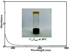 | ||
| Fig. 1 Ultraviolet-visible absorption spectrum of C12Tadd in methanol and image of C12Tadd at 30 °C. | ||
2.4 Electrode preparation and DSSC fabrication
The photoanode was prepared by screen printing TiO2 film (0.4 cm × 0.4 cm) on a fluorine-doped tin oxide (FTO) glass substrate as described in the literature.9 An 8 μm thick layer of 20 nm-sized TiO2 particles was first printed on the substrate and a 5 μm thick scatting layer of 400 nm-sized TiO2 particles was further coated. The sintered TiO2 electrode was immersed into a 0.2 mM ethanol solution of the Z907Na sensitizer for 20 h. The active area of the photoanode was 0.16 cm2.The carbon/PEDOT composite nanoparticle CE was prepared as follow. The carbon ink was spin-coated on a FTO glass substrate at 2000 rpm for 1 min, then the substrate was baked at 200 °C for 30 min to obtain a carbon electrode. The carbon/PEDOT composite electrode was further prepared by electrochemical polymerization of 3,4-ethylenedioxythiophene (EDOT) monomer on the carbon electrode via cyclic voltammetry (CV) technology using a three-electrode system.20 The working electrode, the counter electrode and the reference electrode in the three-electrode system were the carbon electrode, a freshly polished Pt foil electrode and an aqueous Ag/AgCl reference electrode, respectively. The electrolyte for EDOT polymerization was composed of 0.1 mol L−1 lithium bis(trifluoromethanesulfonyl) imide and 0.02 mol L−1 EDOT in acetonitrile. The applied voltage range of CV for EDOT polymerization was −0.4 V to 1.2 V with a scan rate of 10 mV s−1. After that, the composite electrode was baked at 85 °C for 20 min. The carbon/PEDOT composite CE and pure carbon CE were non-transparent, as shown in ESI Fig. 4a.† A Pt CE was also prepared as reference by thermal decomposition method as described in the literature.29
The appropriate amount of the prepared electrolyte (3–5 mg) was sandwiched between the photoanode and CE and then sealed with a hot-melt Surlyn at 70 °C. The DSSCs equipped with carbon/PEDOT composite CE and C12Tadd electrolyte, carbon/PEDOT composite CE and C12T electrolyte, carbon CE and C12Tadd electrolyte, and Pt CE and C12Tadd electrolyte were denoted as CP-C12Tadd, CP-C12T, C–C12Tadd and Pt–C12Tadd, respectively. The images of the prepared DSSCs are shown in ESI Fig. 4b.†
3. Results and discussion
3.1 Impact of additives on liquid crystal electrolytes
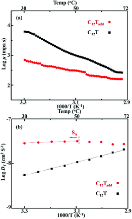
As we reported previously, C12T exhibited smectic A (SA) phase from 12.5 to 75.5 °C.16 After doping with the additives, the liquid crystal mesophase preserved in C12Tadd. DSC measurements, POM observations and SAXS analyses (see the ESI†) confirmed the presence of the SA phase of C12Tadd over a temperature range from 0 to 51 °C and a lamellar structure with an interlayer spacing of 3.29 nm formed in smectic C12Tadd. These results suggested that C12Tadd formed lamellar nanostructures in the smectic phase, as shown in inset of ESI Fig. 1b,† which could assemble layered pathways for efficient charge transport.16In order to further clarify the impact of doped additives on the liquid crystal electrolytes, temperature dependent viscosities (μ) of the liquid crystal electrolytes were determined by rotational rheometer. As shown in Fig. 2a, the viscosities of C12Tadd were greatly lowered after doping the liquid TBP and LiClO4 in C12T. Despite a relatively low viscosity, C12Tadd was still too viscous to flow at room temperature (inset of Fig. 1) and non-volatile at 40 °C for 48 h under vacuum condition (see the ESI†). Since the charge diffusion in the electrolytes is related to the viscosity, the lowered viscosity would favor the charge diffusion. Temperature dependent diffusion coefficients (DT) of C12Tadd were further characterized by CV measurements (see the ESI†) using a symmetric thin-film setup as described in the literature.30 As shown in Fig. 2b, the obtained DT increased with the increase in temperature for both the smectic electrolytes and the log![[thin space (1/6-em)]](https://www.rsc.org/images/entities/char_2009.gif) DT was approximately linearly dependent on T−1. DT decreased by 15% at the SA phase to isotropic liquid phase transition point for C12Tadd, which indicated the beneficial effect of lamellar nanostructures on the charge transport. By doping with the additives, the charge diffusion coefficient of lamellar nanostructured C12Tadd were greatly improved compared with the undoped C12T. Meanwhile, the slope of log
DT was approximately linearly dependent on T−1. DT decreased by 15% at the SA phase to isotropic liquid phase transition point for C12Tadd, which indicated the beneficial effect of lamellar nanostructures on the charge transport. By doping with the additives, the charge diffusion coefficient of lamellar nanostructured C12Tadd were greatly improved compared with the undoped C12T. Meanwhile, the slope of log![[thin space (1/6-em)]](https://www.rsc.org/images/entities/char_2009.gif) DT versus T−1 for smectic C12Tadd was much lower than that for smectic C12T, suggesting a lower activation energy for charge transport in C12Tadd. These results indicated that the introduced additives favoured the charge diffusion in lamellar T−/T2 nanostructures.
DT versus T−1 for smectic C12Tadd was much lower than that for smectic C12T, suggesting a lower activation energy for charge transport in C12Tadd. These results indicated that the introduced additives favoured the charge diffusion in lamellar T−/T2 nanostructures.
3.2 The morphology of the CEs
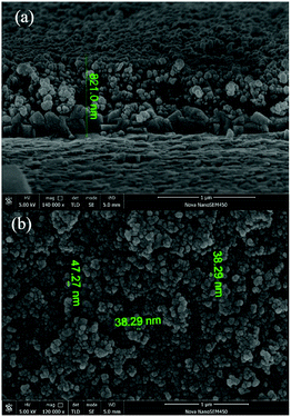
The morphologies of the prepared carbon/PEDOT composite CE and pure carbon CE were revealed by SEM observations (ESI Fig. 3† and 3). As shown in ESI Fig. 3a,† the morphology of the coated carbon electrode exhibited spherical nanoparticular structures on the FTO substrate with an average diameter of about 35 nm. This result suggested that the carbon CE could provide a high surface area for charge transfer at the interface between the CE and the electrolyte in DSSCs. Although the carbon was an alternative CE material comparative to Pt due to the abundance, low cost and high electrical conductivity and catalytic surface area,31 the carbon electrode could to be further optimized for the T−/T2 systems for high efficient DSSCs due to the relatively slow kinetics of the electrochemical reaction and insufficient electrocatalytic activity.20–23 PEDOT is also an alternative CE material with excellent electrocatalytic activity towards the T−/T2 mediator.23,25 However, the conductivity of PEDOT electrode via spin coating is relatively low for the application in DSSCs.32 In view of these, we employed the advantages of carbon and PEDOT materials and prepared the carbon/PEDOT composite electrode for the smectic T−/T2 based DSSC via spin coating and electrochemical polymerization deposition method. For the carbon/PEDOT composite electrode (Fig. 3), the carbon nanoparticles provided considerable surface area for PEDOT deposition and the PEDOT was homogeneously attached to the carbon nanoparticles to form carbon/PEDOT composite nanoparticle electrode on the FTO substrate. The EDS mapping image (ESI Fig. S6†) of the carbon/PEDOT composite nanoparticle electrode revealed the uniform distribution of sulfur atom, which indicated the successful electrochemical polymerization of EDOT monomer on the carbon electrode. The thickness of the carbon/PEDOT nanoparticle layer was uniform with a size of about 800 nm (Fig. 3a). The average diameter of the carbon/PEDOT composite nanoparticle was around 40 nm (Fig. 3b). The square resistances of the prepared carbon electrode and carbon/PEDOT composite electrode were about 27 and 35 Ω cm−2, respectively.3.3 Photovoltaic performance of DSSCs
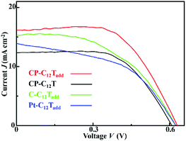
The photovoltaic performance of the prepared DSSCs were evaluated by J–V measurements under simulated AM1.5G solar light (100 mW cm−2). The J–V curves of the DSSCs at 30 °C are shown in Fig. 4. The Jsc, Voc, FF and PCE of the DSSCs obtained from the J–V curves are listed in Table 1. The C–C12Tadd and Pt–C12Tadd exhibited considerable Jsc (>14 mA cm−2) and Voc (about 0.62 V). The Jsc of C–C12Tadd was higher than that of Pt–C12Tadd, which was probably due to a larger surface area. However, both the cells suffered from low FF (<0.5), resulting in a limited PCE. Introducing PEDOT layers between the carbon nanoparticles and the electrolyte led to a desirable improvement in FF for CP-C12Tadd. The improved FF indicated the introduced PEDOT layers favoured the charge transfer process at the CE/electrolyte interface. At 30 °C, the Jsc, Voc, FF and PCE of CP-C12Tadd were 15.8 mA cm−2, 0.642 V, 0.568 and 5.76%, respectively. TBP and LiClO4 were reported as effective additives capable of enhancing the photovoltaic performance of DSSCs.4 By comparing the photovoltaic performance of CP-C12Tadd and CP-C12T, the presence of the additives in the liquid crystal electrolyte produced a remarkable increase in overall photovoltaic paraments for CP-C12Tadd, resulting in an improvement of PCE from 3.83% to 5.76%. The impacts of the additives and the electrodes on the improved performance for the liquid crystal electrolyte based DSSCs were further analyzed by EIS measurement, which was discussed in Section 3.4.| DSSC | Jsc (mA cm−2) | Voc (V) | FF | PCE | RCEa (Ω cm−2) |
|---|---|---|---|---|---|
| a Calculated from the half resistance value of the EIS fitting multiplied by the geometric surface area of the symmetric cell. | |||||
| Pt–C12Tadd | 14.0 | 0.621 | 0.455 | 3.96% | 88 |
| C–C12Tadd | 15.1 | 0.621 | 0.488 | 4.57% | 60 |
| CP-C12Tadd | 15.8 | 0.642 | 0.568 | 5.76% | 29 |
| CP-C12T | 11.8 | 0.617 | 0.527 | 3.83% | 38 |
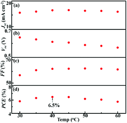
Typically, DSSCs based on commonly used electrolytes would suffer from deteriorated efficiency at elevated temperatures, which is one of the most challenging issues in solar cell technology.33 Nevertheless, liquid crystal electrolytes possess non-volatile and thermally stable properties, which have shown advantages in DSSCs at elevated temperatures.14–16 In order to evaluate the temperature dependent performance of the smectic C12Tadd based DSSC, photovoltaic characterization of CP-C12Tadd was further performed during the heating process from 30 to 60 °C. The obtained Jsc, Voc, FF and PCE are presented in Fig. 5. The Jsc of CP-C12Tadd (Fig. 5a) increased with increasing temperature and reached the maximum of 17.1 mA cm−2 at 45 °C. After that, the Jsc decreased from 50 to 60 °C due to the absence of the lamellar nanostructures. The Voc of CP-C12Tadd (Fig. 5b) decayed from 0.644 V to 0.570 V during heating the cell from 30 to 60 °C, while the FF of CP-C12Tadd (Fig. 5c) increased from 0.568 to 0.624. The temperature dependence of the photovoltaic parameters for CP-C12Tadd was in consistent with that of the reported liquid crystal electrolyte based DSSCs.15,16 Owing to the optimization on the electrolyte and CE, CP-C12Tadd achieved a maximum PCE of 6.5% at 40 °C, which was enhanced by 100% than that of pure [C12MIm][T]/T2 and Pt CE based DSSCs at the same temperature.16 To the best of our knowledge, this was the highest PCE achieved by liquid crystal electrolyte based DSSCs. Notably, the CP-C12Tadd maintained relatively stable photovoltaic performance with PCE higher than 6.0% within a temperature range from 35 to 55 °C, which have great potential for operating at outdoor conditions.
3.4 Impact of CE and additives on the DSSC interfaces
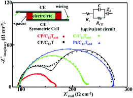
EIS measurements were applied to analysis the impact of the additives and CE on the DSSC interfaces between the electrodes and electrolyte. Symmetric cells (inset of Fig. 6) were firstly employed to reveal the impact of additives and CE on the CE/electrolytes interface.34 The Nyquist plots of the symmetric cells obtained from EIS measurements at 0 V bias potential under 30 °C are shown in Fig. 6. On the basis of EIS theory, the ideal Nyquist plot of the symmetric cell should compose of a semicircle at high frequency due to the charge transfer at the electrode/electrolyte interface and a Warburg impedance caused by ion diffusion through the electrolyte at the medium frequency.34 This ideal spectrum was observed in the case of the symmetric cells based on composite electrode and liquid crystal electrolytes. However, the Warburg impedance was undetected during the measured frequency for the Pt electrode and pure carbon electrode based cells. Similar phenomenon was also observed for the reported DSSCs with T−/T2 and Pt systems.22 The charge transfer resistance (RCE, Ω cm−2) at the electrode/electrolyte interface was calculated from the half resistance value of the EIS fitting multiplied by the geometric surface area of the symmetric cell and listed in Table 1. Obviously, the RCE value of the carbon/PEDOT electrode is much lower than that of the Pt electrode and pure carbon electrode, indicating an improved charge transfer process between the carbon/PEDOT electrode and C12Tadd. Another important parameter in the EIS characterization is the frequency of the characteristic response peaks in the high frequency region of the Bode plot, signifying the electron transfer rate at the electrode/electrolyte interface. The frequency of the characteristic response peak (listed in Fig. 6) for the carbon/PEDOT electrode was much higher than that of the Pt electrode and pure carbon electrode, revealing a faster electron transfer rate at the interface of carbon/PEDOT electrode and C12Tadd.35 These implied that coating of PEDOT on carbon nanoparticles provided good electrocatalytic activity for disulfide reduction, leading to a higher FF in the DSSCs for improved PCE.Typically, additives, such as TBP and LiClO4, could optimize the charge transfer at the WE/electrolyte interface via suppressing the electron recombination and shifting the TiO2 conduction band for electron injection in DSSCs to promote photovoltaic performance.4 However, effect of the additives on liquid crystal electrolyte based DSSCs has yet to be explored. As shown in Fig. 6, C12Tadd possessed a lower RCE at the CE/electrolyte interface and a much smaller bulk resistance (Rb = 14 Ω cm−2, derived from the Warburg impedance at the medium frequency) for efficient ion diffusion compared with C12T (Rb = 86 Ω cm−2). These should be response for the higher Jsc and FF in CP-C12Tadd. EIS measurements of the prepared DSSCs were further conducted under dark conditions at a bias voltage of −0.6 V to analyze the effect of additives on the WE/electrolytes interface. The Nyquist plots of CP-C12Tadd and CP-C12Tadd obtained at 30 °C are shown in Fig. 7. Both the impedance spectra consisted of two semicircles and the medium frequency semicircle represented electron recombination process at the WE/electrolyte interface.36 The recombination resistance (Rrec) could be extracted by fitting the equivalent circuit to the measured spectrum and higher Rrec corresponded to lower recombination rate, which is beneficial to photovoltaic performance because of the increased electron injection into the TiO2.2 The Rrec of CP-C12Tadd (51 Ω cm−2) was much higher than that of CP-C12T (22 Ω cm−2), which suggested that the doped additives impeded the unfavored electron recombination, leading to the higher Voc of CP-C12T. These EIS measurement results indicated that doping of the additives in the liquid crystal electrolyte favored the overall charge transfer process in DSSC, which improved the FF, Voc and Jsc of the T−/T2 liquid crystal electrolyte based DSSC.
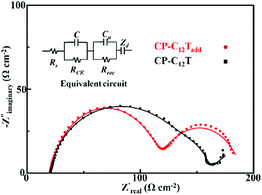 | ||
| Fig. 7 Nyquist plots of the CP-C12Tadd and CP-C12T obtained from EIS measurements at 30 °C (discrete symbols: experimental results, solid lines: fitted data, inset is the equivalent circuit). | ||
4. Conclusions
A TBP and LiClO4 doped lamellar nanostructured smectic electrolyte based on thiolate/disulfide redox couple and a carbon/PEDOT composite nanoparticle electrode were prepared for optimizing the photovoltaic performance of DSSCs. The introduction of the additives in the lamellar thiolate/disulfide nanostructures lowered the viscosity of the electrolyte and improved the overall charge transfer process in the DSSC. The composite nanoparticle CE provided good catalytic activity and large surface area charge transfer at the CE/electrolyte interface. As a result, the FF, Jsc and Voc of the DSSC employing the optimized smectic thiolate/disulfide electrolyte and the composite electrode were greatly enhanced and an improved PCE value of 6.5% was obtained at 40 °C under simulated AM1.5G solar light. Notably, the derived DSSC maintained stable photovoltaic performance with PCE higher than 6.0% within a temperature range from 35 to 55 °C, which shows great potential of the organic liquid crystal electrolytes based DSSCs towards practical application.Conflicts of interest
There are no conflicts to declare.Acknowledgements
This work was supported by the National Natural Science Foundation of China (No. 21805199).Notes and references
- B. O'Regan and M. Grätzel, Nature, 1991, 353, 737 CrossRef.
- A. Hagfeldt, G. Boschloo, L. Sun, L. Kloo and H. Pettersson, Chem. Rev., 2010, 110, 6595 CrossRef CAS.
- S. Mathew, A. Yella, P. Gao, R. Humphry-Baker, B. Curchod, N. Ashari-Astani, I. Tavernelli, U. Rothlisberger, M. Nazeeruddin and M. Grätzel, Nat. Chem., 2014, 6, 242 CrossRef CAS.
- J. Wu, Z. Lan, J. Lin, M. Huang, Y. Huang, L. Fan and G. Luo, Chem. Rev., 2015, 115, 2136 CrossRef CAS.
- Q. Yu, Y. Wang, Z. Yi, N. Zu, J. Zhang, M. Zhang and P. Wang, ACS Nano, 2010, 4, 6032 CrossRef CAS.
- A. Yella, H. Lee, H. Tsao, C. Yi, A. Chandiran, M. Nazeeruddin, E. Diau, C. Yeh, S. Zakeeruddin and M. Grätzel, Science, 2011, 334, 629 CrossRef CAS.
- A. Lennert, M. Sternberg, K. Meyer, R. Costa and D. Guldi, ACS Appl. Mater. Interfaces, 2017, 9, 33437 CrossRef CAS PubMed.
- Z. Zhang, P. Chen, T. Murakami, S. Zakeeruddin and M. Grätzel, Adv. Funct. Mater., 2008, 18, 341 CrossRef CAS.
- M. Wang, N. Chamberland, L. Breau, J. Moser, R. Humphry-Baker, B. Marsan, S. Zakeeruddin and M. Grätzel, Nat. Chem., 2010, 2, 385 CrossRef CAS.
- X. Xu, K. Cao, D. Huang, Y. Shen and M. Wang, J. Phys. Chem. C, 2012, 116, 25233 CrossRef CAS.
- J. Liu, X. Yang, J. Cong, L. Kloo and L. Sun, Phys. Chem. Chem. Phys., 2012, 14, 11592 RSC.
- K. Goossens, K. Lava, C. Bielawski and K. Binnemans, Chem. Rev., 2016, 116, 4643 CrossRef CAS.
- N. Yamanaka, R. Kawano, W. Kubo, T. Kitamura, Y. Wada, M. Watanabe and S. Yanagida, Chem. Commun., 2005, 740 RSC.
- R. Costa, F. Werner, X. Wang, P. Grönninger, S. Feihl, F. Kohler, P. Wasserscheid, S. Hibler, R. Beranek, K. Meyer and D. Guldi, Adv. Energy Mater., 2013, 3, 657 CrossRef CAS.
- D. Högberg, B. Soberats, S. Uchida, M. Yoshio, L. Kloo, H. Segawa and T. Kato, Chem. Mater., 2014, 26, 6496 CrossRef.
- S. Tan, Z. Zhao, C. Wang and Y. Wu, Electrochim. Acta, 2018, 288, 165 CrossRef CAS.
- Y. Zhu, H. Guo, H. Zheng, Y. Lin, C. Gao, Q. Han and M. Wu, Nano Energy, 2016, 21, 1 CrossRef CAS.
- A. Hilmi, T. Shoker and T. Ghaddar, ACS Appl. Mater. Interfaces, 2014, 6, 8744 CrossRef CAS.
- H. Wu, Z. Lv, S. Hou, X. Cai, D. Wang, H. Kafafy, Y. Fu, C. Zhang, Z. Chu and D. Zou, J. Power Sources, 2013, 221, 328 CrossRef CAS.
- J. Zhang, H. Long, S. Miralles, J. Bisquert, F. Fabregat-Santiago and M. Zhang, Phys. Chem. Chem. Phys., 2012, 14, 7131 RSC.
- H. Wu, Z. Lv, Z. Chu, D. Wang, S. Hou and D. Zou, J. Mater. Chem., 2011, 21, 14815 RSC.
- G. Liu, X. Li, H. Wang, Y. Rong, Z. Ku, M. Xu, L. Liu, M. Hu, Y. Yang and H. Han, Carbon, 2013, 53, 11 CrossRef CAS.
- H. Tian, Z. Yu, A. Hagfeldt, L. Kloo and L. Sun, J. Am. Chem. Soc., 2011, 133, 9413 CrossRef CAS PubMed.
- H. Tian, E. Gabrielsson, Z. Yu, A. Hagfeldt, L. Kloo and L. Sun, Chem. Commun., 2011, 47, 10124 RSC.
- J. Burschka, V. Brault, S. Ahmad, L. Breau, M. Nazeeruddin, B. Marsan, S. Zakeeruddin and M. Grätzel, Energy Environ. Sci., 2012, 5, 6089 RSC.
- K. Meng and K. Thampi, ACS Appl. Mater. Interfaces, 2014, 6, 20768 CrossRef CAS.
- J. Theerthagiri, R. Senthil, M. Buraidah, J. Madhavan, A. Arof and M. Ashokkumar, J. Mater. Chem. A, 2016, 4, 16119 RSC.
- J. Theerthagiri, R. Senthil, P. Arunachalam, K. Bhabu, A. Selvi, J. Madhavan, K. Murugan and A. Arof, Ionics, 2017, 23, 1017 CrossRef CAS.
- Y. Zhang, Z. Sun, C. Shi and F. Yan, RSC Adv., 2016, 6, 70460 RSC.
- M. Berginc, U. Krašovec, M. Jankovec and M. Topič, Sol. Energy Mater. Sol. Cells, 2007, 91, 821 CrossRef CAS.
- J. Wu, Z. Lan, J. Lin, M. Huang, Y. Huang, L. Fan, G. Luo, Y. Lin, Y. Xie and Y. Wei, Chem. Soc. Rev., 2017, 46, 5975 RSC.
- J. Chen, H. Wei and K. Ho, Sol. Energy Mater. Sol. Cells, 2007, 91, 1472 CrossRef CAS.
- S. Raga and F. Fabregat-Santiago, Phys. Chem. Chem. Phys., 2013, 15, 2328 RSC.
- T. Wei, C. Wan, Y. Wang, C. Chen and H. Shiu, J. Phys. Chem. C, 2007, 111, 4847 CrossRef CAS.
- F. Hao, Z. Wang, Q. Luo, J. Lou, J. Li, J. Wang, S. Fan, K. Jiang and H. Lin, J. Mater. Chem., 2012, 22, 22756 RSC.
- Z. Xu, X. Yin, Y. Guo, Y. Pu and M. He, J. Mater. Chem. C, 2018, 6, 4746 RSC.
Footnote |
| † Electronic supplementary information (ESI) available: DSC measurements, POM observations, SAXS analyses, volatile, cyclic voltammetry measurements of the electrolytes, images of the electrodes and DSSCs, and SEM image of the carbon electrode. See DOI: 10.1039/c9ra07043e |
| This journal is © The Royal Society of Chemistry 2019 |

