 Open Access Article
A germanium and zinc chalcogenide as an anode for a high-capacity and long cycle life lithium battery †
Xu Chen‡
a,
Jian Zhou‡a,
Jiarui Lia,
Haiyan Luoa,
Lin Meia,
Tao Wang *a,
Jian Zhu
 *a and
Yong Zhang*b
aState Key Laboratory for Chemo/Biosensing and Chemometrics, College of Chemistry Institution, Hunan University, Changsha 410082, China. E-mail: jzhu@hnu.edu.cn
bFujian Provincial Key Laboratory of Functional Materials and Applications, Xiamen University of Technology, Xiamen 361024, China
First published on 30th October 2019
Abstract
High-performance lithium ion batteries are ideal energy storage devices for both grid-scale and large-scale applications. Germanium, possessing a high theoretical capacity, is a promising anode material for lithium ion batteries, but still faces poor cyclability due to huge volume changes during the lithium alloying/dealloying process. Herein, we synthesized an amorphous germanium and zinc chalcogenide (GZC) with a hierarchically porous structure via a solvothermal reaction. As an anode material in a lithium ion battery, the GZC electrode exhibits a high reversible capacity of 747 mA h g−1 after 350 cycles at a current density of 100 mA g−1 and a stable capacity of 370 mA h g−1 after 500 cycles at a current density of 1000 mA g−1 along with 92% capacity retention. All of these outstanding electrochemical properties are attributed to the hierarchically porous structure of the electrode that has a large surface area, fast ion conductivity and superior structural stability, which buffers the volumetric variation during charge/discharge processes and also makes it easier for the electrolyte to soak in, affording more electrochemically active sites.
1. Introduction
Over the last few decades, lithium ion batteries (LIBs) have been proposed as a promising type of energy storage device for application in portable electronic equipment and smart grids.1–5 However, the currently available LIBs with graphitic carbon as the anode material cannot satisfy the continuously increasing requirements of electric vehicles and large-scale energy storage applications.6,7 To meet the growing power-supply demand, tremendous efforts have been made to develop LIBs with high energy density and long-lasting cycle performance.Germanium, as a homologue of carbon with similar redox chemistry, is considered as an alternative, with a great foreground development, to commercial carbon materials for LIBs. Compared with commercial carbon materials (370 mA h g−1), Ge has a higher theoretical capacity (1624 mA h g−1 for Li22Ge5 and 1384 mA h g−1 for Li15Ge).8,9 In addition, Ge has other unique properties, such as a faster Li+ diffusion rate (400 times faster than Si), and superior conductivity (100 times greater than that of Si).10,11 Due to these advantages, Ge-based materials have attracted more and more attention in recent years. Nevertheless, Ge-based materials have been suffering from poor cyclability in the process of becoming commercialized anode materials. During lithium alloying/dealloying reactions, devastating expansion and contraction take place inside the electrode, which leads to the pulverization of the electrode material and eventual decay of the performance of the battery.12,13 Numerous strategies have been applied to alleviate the volume change and improve the electrochemical properties, including nanosizing the Ge particles,14–16 modifying the surface by coating,16,17 doping with other elements18–20 and introducing a porous structure.21,22 All of these methods have partially improved the electrochemical performance of Ge-based electrode materials and can be categorised into two approaches: changing the component or shaping an efficacious structure and morphology.
Among those strategies, a number of papers have reported that germanium chalcogenide anode materials, such as binary sulfides and especially ternary sulfides, exhibit a great cycling performance.13,23–25 In terms of the components, the use of sulfur compounds could mitigate the volume-change stress by forming an in situ Li2S inert matrix. It is suggested that compounds such as GeS and GeS2 are irreversibly converted to Ge in the first cycle: GeS + 2Li+ + 2e− → Ge + Li2S.15 Ge as the active material can then efficiently store and release Li+ according to the reversible alloying and dealloying reaction: Ge + xLi+ + xe− → 4LixGe (0 ≤ x ≤ 4.4); during this process Li2S surrounding Ge acts as a buffer, thus retarding the volume change. Moreover, compared with their binary counterparts, ternary germanium chalcogenides form an anode that exhibits a better electrochemical performance for LIBs.24,25 The introduction of another metal like Zn, which is also an electrochemically active species, can also accommodate the volume change during the charge/discharge process thus leading to long-term cycling stability.26–28
Herein, we report on a germanium and zinc chalcogenide (GZC) and have investigated the electrochemical performance of the GZC electrode for the first time. The GZC with its hierarchically porous structure and fast ion conductivity not only offers sufficient space to overcome the damage caused by the volume expansion of active materials during charge and discharge processes, but also provides highly efficient channels for the fast transport of lithium ions and abundant electrochemically active sites to achieve higher reversible capacity. Thus, the unique structural design affords outstanding battery performance (747 mA h g−1 at a current density of 100 mA g−1 over 350 cycles and 370 mA h g−1 at a high current density of 1000 mA g−1 after 500 continuous cycles), establishing this novel electrode as a very promising prospect in the field of high-capacity and long-life energy storage.
2. Experimental
2.1 Synthesis of GZC-120-ZnGeS
The solvothermal synthesis of GZC-120-ZnGeS is described elsewhere.29 First, powdered Ge (0.089 g, 1.23 mmol), Zn(NO3)2·6H2O (0.089 g, 0.30 mmol), and sulfur (S, 0.220 g, 6.88 mmol) were dispersed in N-(2-aminoethyl)morpholine (AEM, 2.5 mL) solution. After stirring for approximately 30 min, the mixture was transferred and sealed into a Teflon-lined stainless-steel autoclave with a 23 mL inner volume. The container was then heated at 190 °C in an electric oven. 12 days later, large light-yellow rhombic dodecahedral crystals of GZC-120-ZnGeS were finally obtained.2.2 Materials characterization
Scanning electron microscopy (SEM, Zeiss, Germany) and transmission electron microscopy (TEM, FEI Tecnai G2 F20, operating at 200 kV, America) were used to investigate the microstructural morphology of the GZC material. All of the BET surface area tests were carried out using a Micromeritics ASAP 2020 HD88 system (Mack, America). The surface characteristics of the samples were investigated via X-ray photoelectron spectroscopy (XPS, Surface Analysis PHI5600, Physical Electronics).2.3 Electrochemical measurements
The electrochemical characterization of the material was carried out using coin cells (CR2032) assembled in an argon-filled glove box, with Li metal as the counter/reference electrode, and 1 M LiPF6 in EC-DEC solution (ethylene carbonate and diethyl carbonate, 1![[thin space (1/6-em)]](https://www.rsc.org/images/entities/char_2009.gif) :
:![[thin space (1/6-em)]](https://www.rsc.org/images/entities/char_2009.gif) 1 volumetric ratio) as the electrolyte. The working electrode was prepared by casting the slurry onto a copper foil and then drying at 70 °C for 12 h under vacuum. Typically, the slurry was a mixture of active material, acetylene black and sodium carboxymethyl cellulose (CMC) with a weight ratio of 6
1 volumetric ratio) as the electrolyte. The working electrode was prepared by casting the slurry onto a copper foil and then drying at 70 °C for 12 h under vacuum. Typically, the slurry was a mixture of active material, acetylene black and sodium carboxymethyl cellulose (CMC) with a weight ratio of 6![[thin space (1/6-em)]](https://www.rsc.org/images/entities/char_2009.gif) :
:![[thin space (1/6-em)]](https://www.rsc.org/images/entities/char_2009.gif) 3
3![[thin space (1/6-em)]](https://www.rsc.org/images/entities/char_2009.gif) :
:![[thin space (1/6-em)]](https://www.rsc.org/images/entities/char_2009.gif) 1. The mass loading of active material was approximately 0.5 mg. The process of galvanostatic charge/discharge was measured using Arbin Instruments BT 2000 apparatus. An electrochemical workstation was used to conduct the cyclic voltammetry (CV) and electrochemical impedance spectroscopy (EIS) tests.
1. The mass loading of active material was approximately 0.5 mg. The process of galvanostatic charge/discharge was measured using Arbin Instruments BT 2000 apparatus. An electrochemical workstation was used to conduct the cyclic voltammetry (CV) and electrochemical impedance spectroscopy (EIS) tests.
3. Results and discussion
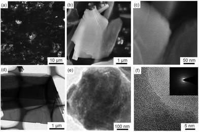
Fig. 1 displays the microstructure and general morphology of the GZC via SEM and TEM. Fig. 1a is a low magnification SEM image, showing that the GZC consists of a large number of thin sheets with a film size ranging from 1 to 10 μm. Fig. 1b and c indicate the typical nanosheet morphology of the GZC. This unique 2D structure is due to the combined effect of temperature and barometric pressure of thermal transformation. The thin sheet structure and ordered porous structure can be observed much more clearly by TEM in Fig. 1d and e, respectively. As an anode material for LIBs, this hierarchical structure could provide highly efficient ion transporting channels and adequate free space to tolerate the volumetric change during cycles.30 The inset in Fig. 1f shows the electron diffraction pattern, further confirming that GZC has no crystal lattice and is amorphous. | ||
| Fig. 1 Morphological characterization of the GZC: SEM images of the GZC at different magnifications (a–c) and TEM images of the GZC at different magnifications (d–f). | ||
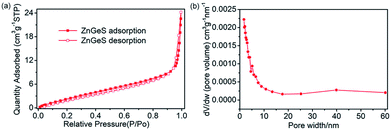
As is known, to some extent the size and structure of pores can determine the electrochemical properties of an electrode material.31 Therefore, nitrogen adsorption and desorption isotherms were used to evaluate the surface area and pore size distribution of the GZC. Fig. 2a shows the N2 adsorption and desorption isotherms for the GZC. It is obvious that the quantity of N2 adsorbed representing the pore volume gradually increases until the relative pressure reaches 0.9. Referring to the relevant literature, this is the characteristic of Type III adsorption isotherms,32,33 which confirms the existence of some macropores as shown in Fig. 2b and the multilayer formation shown in the SEM and TEM images in Fig. 1. In addition, the calculated Brunauer–Emmett–Teller (BET) specific surface area of the GZC is approximately 12.6043 m2 g−1. The presentation of the pore distribution in Fig. 2b reveals that the pore size mainly distributes in the range of 0–6 nm, suggesting most of the pores belong to the micropore (<2 nm) and mesopore (2–8 nm) classes. We also collected the XPS results from the surface of the sample (Fig. S1 in the ESI†), which show the valence state of Ge, S and Zn, along with the atomic ratios of C, N, O, S, Zn and Ge elements in the GZC composite.
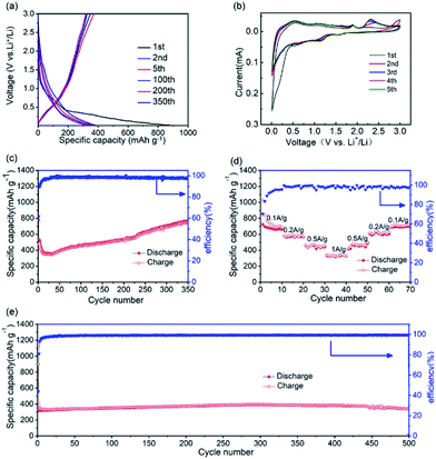
As an anode material, the electrochemical performance of the GZC was researched using half-cells with Li foils as counter electrodes. Fig. 3a demonstrates the charge and discharge voltage profiles of the GZC at the current density of 1000 mA g−1 for 1, 2, 5, 100, 200 and 350 cycles in the voltage range of 0.01–3.0 V (vs. Li/Li+). Correspondingly, the first five cyclic voltammetry (CV) curves of the GZC electrode at a scan rate of 0.1 mV s−1 in the voltage window of 0.01–3.0 V (vs. Li/Li+) are presented in Fig. 3b. The first discharge and charge capacities are 899.6 and 326.7 mA h g−1, respectively, with an initial coulombic efficiency of 43.9%, indicating a high irreversible reaction in the first cycle. The reason for the high initial capacity loss is the formation of the solid electrolyte interface (SEI) layer and the decomposition of electrolyte.34 After the first four cycles, the battery began to maintain stability with a capacity levelling at approximately 350 mA h g−1 and a coulombic efficiency approaching 100% up to 400 cycles. During the initial cathodic scan, three small reduction peaks can be observed. The small peak appearing at 0.51 V which disappeared from the second cycle is attributed to the decomposition of the GZC.35 The presence of another three reduction peaks at 0.56, 1.13 and 1.52 V after the first cycle could originate from multistep alloying of LixGe and LixZn. The anodic peak at 2.30 V which does not appear in the first cycle is deduced to represent reversible reactions such as: ZnS + 2Li+ + 2e− ↔ Zn + Li2S (and GeS2 + 4Li+ + 4e− ↔ Ge + 2Li2S). Other peaks at 1.83 V and 0.5 V are ascribed to the process of LixGe and LixZn dealloying into Ge and Zn, respectively. The CV curves almost overlap after the first cycle, revealing that the GZC anode has an excellent reversibility and electrochemical stability. Unlike many other LIBs, the capacity of which could possibly degrade constantly after the first cycle, as shown in Fig. 3c, the specific capacity of the GZC electrode unexpectedly increased after the first 30 cycles (346 mA h g−1) up to 350 cycles (747 mA h g−1). This result may be attributed to gradually increased resistance and permeation of the electrolyte into the internal area of the electrode material. To prove this statement, we also carried out electrochemical impedance spectroscopy (EIS) of the GZC electrode as shown in Fig. S2;† the charge transfer resistance (Rct) is gradually increased after the first cycle, which is consistent with the loss of capacity over the first 30 cycles. Afterwards, the Rct began to decrease which correlated well with the enhanced capacity. We can reasonably speculate that a process took place where the electrolyte gradually permeated into the internal area of the electrode material and activated it continuously. In addition, the average capacity from the 1st cycle to the 350th reached 534 mA h g−1, which is a comparably high capacity, with an average coulombic efficiency of approximately 98%.
The rate performance from 0.1 to 1 A g−1 is presented in Fig. 3d. At current densities of 0.1, 0.2, 0.5 and 1 A g−1, the GZC electrode exhibits specific capacities of 716, 580, 456 and 335 mA h g−1, respectively. More importantly, when the current density returned back to 0.1 A g−1, the GZC still retained a specific capacity of 692 mA h g−1 with only 3% capacity degradation, signifying the fast reaction kinetics and exceptional stability of the GZC electrode.
In order to further explore the long-term cycling performance of the GZC electrode, galvanostatic charge and discharge measurements at a current density of 1 A g−1 were carried out. As displayed in Fig. 3e, it exhibits a high capacity of 352 mA h g−1 at the 100th cycle and 337 mA h g−1 at the 500th cycle with a capacity retention of 96%, which indicates an exceedingly good cycling performance compared with previous reports regarding the use of Ge-based material as electrodes. The terrific cycling performance could be attributed to the advantages of the distinctive structural design of the GZC provides. Firstly, the hierarchically porous structure with superior structural stability possesses sufficient void space throughout the whole electrode, allowing the active electrode to expand freely without rupturing the whole electrode structure, thereby achieving excellent cycling stability. Moreover, the porous design with its mesoporous and microporous structure offers highly efficient channels for the fast transport of lithium ions during cycling, resulting in continuous high capacity.
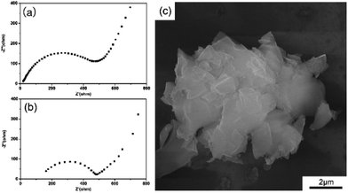
Fig. 4a and b exhibit the Nyquist plots of the GZC electrode before cycling and after 600 cycles, respectively. It is obvious that in each graph there is a semicircle in the high-frequency region and a straight line in the low-frequency region. The diameter of the semicircle is related to the Rct, the increase in which is the main cause of the loss of capacity.36 It is apparent that the Rct value of the initial cell is much lower than that after cycling, which is consistent with the outstanding cycling performance of the GZC electrode. Finally, a half-cell applying the GZC as the anode material was disassembled after 1000 cycles at 1 A g−1 so that the morphology change after repetitive charge and discharge processes could be investigated. The cell was disassembled in an Ar-filled glove box, washed with dimethyl carbon (DMC) three times and dried for 12 h before SEM examination. As Fig. 4c shows, the nanosheet structure of the GZC is still maintained overall and no obvious pulverization could be observed, demonstrating the good structural stability of the GZC material.
 | ||
| Fig. 4 (a) Nyquist plot of the GZC electrode in the fresh state. (b) Nyquist plot of the GZC electrode after 600 cycles. (c) SEM image of the GZC after 1000 charge–discharge cycles. | ||
4. Conclusions
In conclusion, a novel GZC electrode was synthesized via a solvothermal reaction. The morphology, structure and electrochemical properties were investigated. The hierarchical structure design with high structural stability not only provides efficient channels for the fast transport of lithium ions and more electrochemical active sites, but also relieves volume expansion during cycling, thus achieving continuous high reversible capacity and outstanding cycling stability. Consequently, as an anode material for LIBs, it exhibits a high reversible capacity of 747 mA h g−1 after 350 cycles at a current density of 100 mA g−1 and a high specific capacity of 370 mA h g−1 at a current density of 1000 mA g−1 with 92% capacity retention after 500 cycles. The excellent electrochemical performance indicates great application prospects in the field of future energy storage devices.Conflicts of interest
There are no conflicts to declare.Acknowledgements
This work was financially supported by the National Natural Science Foundation of China (No. 21805076).References
- M. Li, J. Lu, Z. Chen and K. Amine, Adv. Mater., 2018, 30, 1800561 CrossRef.
- J. W. Choi and D. Aurbach, Nat. Rev. Mater., 2016, 1, 16013 CrossRef CAS.
- J. Lu, Z. Chen, F. Pan, Y. Cui and K. Amine, Electrochem. Energy Rev., 2018, 1, 35–53 CrossRef CAS.
- T. Kim, W. Song, D. Y. Son, K. O. Luis and Y. Qi, J. Mater. Chem. A, 2019, 7, 2942–2964 RSC.
- S. Ni, J. Liu, D. Chao and L. Mai, Adv. Energy Mater., 2019, 9, 1803324 CrossRef.
- T. Wang, J. Zhu, Z. Wei, H. Yang, Z. Ma, R. Ma, J. Zhou, Y. Yang, L. Peng, H. Fei, B. Lu and X. Duan, Nano Lett., 2019, 19, 4384–4390 CrossRef CAS.
- P. Albertus, S. Babinec, S. Litzelman and A. Newman, Nat. Energy, 2017, 3, 16–21 CrossRef.
- Q. Zhang, H. Chen, L. Luo, B. Zhao, H. Luo, X. Han, J. Wang, C. Wang, Y. Yang, T. Zhu and M. Liu, Energy Environ. Sci., 2018, 11, 669–681 RSC.
- S. Wu, C. Han, J. Iocozzia, M. Lu, R. Ge, R. Xu and Z. Lin, Angew. Chem., Int. Ed., 2016, 55, 7898–7922 CrossRef CAS PubMed.
- H. Tian, F. Xin, X. Wang, W. He and W. Han, J. Mater., 2015, 1, 153–169 Search PubMed.
- T. Kennedy, M. Brandon and K. M. Ryan, Adv. Mater., 2016, 28, 5696–5704 CrossRef CAS.
- H. Jung, P. K. Allan, Y. Y. Hu, O. J. Borkiewicz, X. L. Wang, W. Q. Han, L. S. Du, C. J. Pickard, P. J. Chupas, K. W. Chapman, A. J. Morris and C. P. Grey, Chem. Mater., 2015, 27, 1031–1041 CrossRef CAS.
- C. Yang, Y. Jiang, X. Liu, X. Zhong and Y. Yu, J. Mater. Chem. A, 2016, 4, 18711–18716 RSC.
- L. Xin, L. Yu-Si, M. M. Harris, L. Jihao, W. Kai-Xue and C. Jie-Sheng, Chem. Eng. J., 2018, 354, 616–622 CrossRef.
- X. Xiao, X. Li, S. Zheng, J. Shao, H. Xue and H. Pang, Adv. Mater. Interfaces, 2017, 4, 1600798 CrossRef.
- D. Li, H. Wang, H. K. Liu and Z. Guo, Adv. Energy Mater., 2016, 6, 1501666 CrossRef.
- B. Wang, Z. Wen, J. Jin, X. Hong, S. Zhang and K. Rui, J. Power Sources, 2017, 342, 521–528 CrossRef CAS.
- W. Cai, J. Zhou, G. Li, K. Zhang and Y. Qian, ACS Appl. Mater. Interfaces, 2016, 8, 27679–27687 CrossRef CAS.
- Y. Fang, R. Liu, L. Zeng, J. Liu, L. Xu, X. He, B. Huang, Q. Chen, M. Wei and Q. Qian, Electrochim. Acta, 2019, 318, 737–774 CrossRef CAS.
- K. Jin, X. Zhou, L. Zhang, X. Xin, G. Wang and Z. Liu, J. Phys. Chem. C, 2013, 117, 21112–21119 CrossRef CAS.
- G. K. Sung and C. M. Park, J. Mater. Chem. A, 2017, 5, 5685–5689 RSC.
- D. Li, H. Wang, T. Zhou, W. Zhang, H. K. Liu and Z. Guo, Adv. Energy Mater., 2017, 7, 1700488 CrossRef.
- T. Kennedy, E. Mullane, H. Geaney, M. Osiak, C. O'Dwyer and K. M. Ryan, Nano Lett., 2014, 14, 716–723 CrossRef CAS.
- L. Fu, C. Zhang, B. Chen, Z. Zhang, X. Wang and J. Zhao, Inorg. Chem. Front., 2017, 4, 541–546 RSC.
- X. Y. Yu and X. W. Lou, Adv. Energy Mater., 2018, 8, 1701592 CrossRef.
- Y. R. Lim, C. S. Jung, H. S. Im, K. Park, J. Park, W. I. Cho and E. H. Cha, J. Mater. Chem. A, 2016, 4, 10691–10699 RSC.
- X. Li, Z. Yang, Y. Fu, L. Qiao, D. Li, H. Yue and D. He, ACS Nano, 2015, 9, 1858–1867 CrossRef CAS.
- M. M. Mahmoud, Y. Cui, M. Rohde, C. Ziebert, G. Link and H. J. Seifert, Materials, 2016, 9, 506 CrossRef.
- Q. Lin, X. Bu, C. Mao, X. Zhao, K. Sasan and P. Feng, J. Am. Chem. Soc., 2015, 137, 6184–6187 CrossRef CAS.
- F. Sun, K. Huang, Y. Liu, T. Gao, Y. Han and J. Zhong, Appl. Surf. Sci., 2013, 266, 300–305 CrossRef CAS.
- N. Nitta and G. Yushin, Part. Part. Syst. Charact., 2014, 31, 317–336 CrossRef CAS.
- M. Kruk and M. Jaroniec, Chem. Mater., 2001, 13, 3169–3183 CrossRef CAS.
- S. Kitagawa, R. Kitaura and S. I. Noro, Angew. Chem., 2004, 43, 2334–2375 CrossRef CAS.
- Y. Yu, C. Yang, Y. Jiang, X. Liu and X. Zhong, J. Mater. Chem. A, 2016, 4, 18711–18716 RSC.
- Y. J. Cho, H. S. Im, Y. Myung, C. H. Kim, H. S. Kim, S. H. Back, Y. R. Lim, C. S. Jung, D. M. Jang, J. Park, E. H. Cha, S. H. Choo, M. S. Song and W. I. Cho, Chem. Commun., 2013, 49, 4661–4663 RSC.
- S. B. Xia, S. W. Yu, L. F. Yao, F. S. Li, X. Li, F. X. Cheng, X. Shen, C. K. Sun, H. Guo and J. J. Liu, Electrochim. Acta, 2019, 296, 746–754 CrossRef CAS.
Footnotes |
| † Electronic supplementary information (ESI) available. See DOI: 10.1039/c9ra06023e |
| ‡ These authors contributed equally to this work. |
| This journal is © The Royal Society of Chemistry 2019 |


