 Open Access Article
Hydrogel-matrix encapsulated Nitinol actuation with self-cooling mechanism†
Manivannan Sivaperuman Kalairaj‡
 a,
Hritwick Banerjee‡a,
Chwee Ming Lim
 bc,
Po-Yen Chen
 *d and
Hongliang Ren
 *a
*a
aDepartment of Biomedical Engineering, National University of Singapore, Singapore. E-mail: ren@nus.edu.sg
bDepartment of Otorhinolaryngology – Head and Neck Surgery, Singapore General Hospital, Singapore
cDuke-NUS Graduate Medical School, Singapore
dDepartment of Chemical and Biomolecular Engineering, National University of Singapore, Singapore. E-mail: checp@nus.edu.sg
First published on 25th October 2019
Abstract
Shape-memory Nitinol holds burgeoning promise as smart actuators due to its effective resilience, high energy density, and scalability for a myriad of mesoscale machines and robotic applications. However, the higher actuation temperature and prolonged cooling time for a cyclic response make Nitinol precarious and less appealing for commercial use. On the contrary, hydrogels belong to the three dimensional (3D) polymer family where the bulk of the matrix encapsulates water (≈80–90 wt%) constituting a compelling heat-trapping medium. In this paper, we demonstrate a novel self-cooling mechanism comprising a Hydrogel-matrix Encapsulated Nitinol Actuator (HENA) where the heat emitted due to the high temperature (200–400 °C) of Nitinol is trapped in the hydrogel-matrix, maintaining a surface temperature of 20–22 °C. For quantitative analysis, we performed control tests with the state-of-the-art Silicone Elastomer Nitinol Actuator (SENA) which maintained a three times or higher temperature profile (65–90 °C) than its HENA counterpart. HENA is able to entrap 85% heat for actuation of 200 cycles while SENA dissipates the same amount in the first cycle. For impending biomedical applications, HENA with a single Nitinol wire shows a bending displacement up to 45% of its length for trans-oral navigation purposes. A HENA soft robotic gripper with two Nitinol wires can carry delicate, low-melting-point food items (e.g. cheese, chocolate, tofu etc.) with different morphologies that weigh up to 450% of its own weight.
1 Introduction
Soft robotics is an evolving subfield of robotics, with diversified applications1–3 from wearable devices4 to tools and manipulators for endoscopic procedures,5,6 as well as biomimetic robots for rescue and exploration.7,8 A large amount of effort has been made in designing effective actuators with programmable matter9–11 to deform a soft, compliant, continuum body to achieve locomotion, manipulation, or other tasks.12 Nitinol actuators, a class of shape memory actuator (SMA),13 have a robust strength to weight ratio,14 are naturally compliant, and have a higher resiliency.15 Nitinol wires are Joule heated by a controlled voltage, which allows for an electronic control system. SMA actuation signals, unlike tendon driven systems, are transmitted through the copper wires and are not significantly affected by the tortuosity of the path. Nitinol can enable the actuation mechanism in endoscopes and guide-wires, to improve the safety of distal control, especially in complicated endoscopic routes.16 Implementation of SMA springs is quite common17–23 due to the larger range of actuation force and energy density. Nitinol wires, on the other hand, have the potential to further reduce device dimensions where commercial Nitinol springs are 300 μm in diameter. On the contrary, Nitinol wires can be as small as 25 μm. Only ref. 14 utilizes Nitinol wires for curvature (with a more than 8 h fabrication process) while ref. 24–26 utilized changes in tendon length of the Nitinol wire to derive bending.Nitinol’s diversified applications coupled with the slow natural cooling time27 can be overcome by several methods such as fan cooling,28 Peltier cooling,29 water jet cooling,30 use of a mobile heat sink,31 cooling with compressed air,32 silicone grease,33 mineral oil, and thermal grease.34 Recently, a Nitinol actuator with integrated water cooling module35 was developed with active control of water velocity and airflow based on the phase of the cycle to improve the actuation. Most of these methods have a control set up and active monitoring of the actuation phases. To cool the Nitinol in the actuator effectively, a static cooling method is more suitable for specific applications such as a robotic joint.31 The cooling of the Nitinol can be achieved by coating Nitinol with a thermally conductive elastomer.15 Hydrogels, on the other hand, with their hydrophilicity can be considered as a coolant, entrapping the thermal energy without the surface temperature changing much.36,37 Here, we demonstrate a self-cooling actuator (≈1 g) at a millimeter to centimeter scale with two degrees of freedom (DOFs) controlled at the distal end with minimal control set up. The actuation is due to Joule heating of a single curvature based Nitinol (shape memory alloy) wire and the antagonistic motion by the sodium alginate hydrogel-matrix, achieving bending angles of 17–35°. We demonstrate HENA navigation in the oral cavity of the cadaver and a soft robotic gripper carrying different morphological objects (1.5–9.2 g). However, Nitinol has a low efficiency (1 to 5%) due to the thermal nature of the phase change,38,39 which limits the battery operation life. In this study, we are using an external DC supply to operate the Nitinol and overcome battery life limitations.
2 Results and discussions
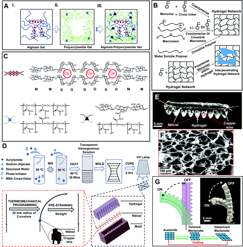
To fabricate the actuator (HENA), we first prepared the hydrogel-matrix (Fig. 1A–C) and then assembled with Nitinol (Fig. 1D). The cross-linking of the hydrogel-matrix is shown schematically in Fig. 1A–C (more information is outlined in the Materials and methods). Inside this PAAm–alginate hydrogel matrix, alginate chains are composed of mannuronic acid (M unit), guluronic acid (G unit), and combinations of both. Moreover, cations like Ca2+ help G blocks to expedite ionic cross-linking and form a water base-alginate hydrogel. On the contrary, polyacrylamide hydrogel based polymer chains are formed via covalent cross-linking. Finally the hybrid alginate–polyacrylamide is formed via covalent cross-linking of the amine group inside the polyacrylamide polymer chains and carboxyl groups on the alginate chains. In order to quantify the level of cross-linking inside the PAAm–alginate hydrogel matrix, Fourier Transform Infrared (FTIR) spectroscopy was conducted in ref. 40. Results of the FTIR incorporated in ref. 40 demonstrated a peak at 1280 cm−1 for C–N stretching. A similar trend of bonds formed between –NH2 groups of polyacrylamide and carboxyl groups of alginate is expected in this study and hence a robust cross-linking is established. Two designs of HENA are fabricated: HENA-C, where the Nitinol is thermomechanically programmed to be curved (with a 20 mm radius of curvature) and is embedded in a straight hydrogel-matrix; and HENA-S, where the Nitinol is thermomechanically programmed to be straight and is embedded in a curved (20 mm radius of curvature) hydrogel-matrix. The design and dimensions of the mold used in the fabrication of HENA-C and HENA-S are explained in detail in the Materials and methods. HENA-C and HENA-S are then tested for their bending performance.2.1 Bending performance of HENA
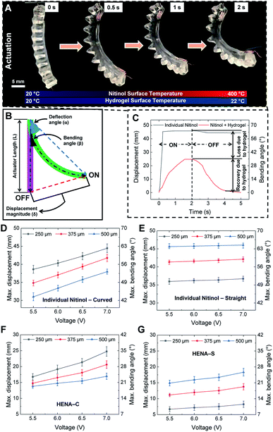
The HENA, which comprises Nitinol and the hydrogel-matrix, is actuated based on Joule heating of the Nitinol, thus the temperature is raised and the martensite fraction converts to the austenite phase, thus the HENA reverts to the programmed configuration (antagonistic to the conformation of the hydrogel-matrix), as shown in Fig. 1G. When deactivated, the hydrogel-matrix, which is stiffer than the martensite Nitinol, defines the total curvature and brings the HENA back to the initial position. During the austenite transformation, Nitinol is stiffer than the hydrogel-matrix, and exerts a force to change the total curvature.The bending performance is tested for different diameters (250 μm, 375 μm, and 500 μm) of Nitinol wires at different voltages (5.5 V, 6 V, 6.5 V, and 7 V). Current is passed through the HENA to cause actuation for 2 s and the HENA is deactivated for a 3 s recovery period, completing a cycle. The maximum displacement of all diameters of individual Nitinol wires that are thermomechanically programmed curved and straight actuated at different voltages is acquired from the change in displacement over a cycle and plotted in Fig. 2D and E, respectively. For both conformations, displacement of individual Nitinol increased sinusoidally during the actuation phase for all diameters (250 μm, 375 μm, and 500 μm). During the recovery phase, 375 μm and 500 μm Nitinol wires remained in the maximum displaced position that was reached at the end of the actuation phase, whereas a slight recovery in the displacement was observed for the 250 μm Nitinol wire. The maximum displacement of the Nitinol programmed curved increased almost 10 mm for a voltage increase from 5.5 V to 7 V and decreased approximately 2 mm for an increase of Nitinol wire diameter from 250 μm to 500 μm. However, the maximum displacement of the Nitinol programmed straight increased only 1 mm for a voltage increase from 5.5 V to 7 V and increased almost 5 mm for an increase of Nitinol wire diameter from 250 μm to 500 μm.
The bending performance of HENA-C and HENA-S is tested for all diameters at all voltages and compared to that of the individual Nitinol wires for the same cycle period. For both the conformations, during the actuation period, HENA reached almost 55% of the displacement achieved by individual Nitinol wire and required more time to reach the peak compared to individual Nitinol wire. Both are due to the active cooling of the Nitinol surface and increase in the weight of the actuator due to the hydrogel-matrix environment. The loss in the displacement is stored as strain energy in the hydrogel-matrix during the actuation phase and is released during the recovery phase to guide it back to its initial position within the recovery period (Fig. 2C) due to the antagonistic design of the hydrogel-matrix to the thermomechanically programmed conformation of Nitinol. The strain energy released by the hydrogel-matrix for both HENA-C and HENA-S in all combinations of Nitinol diameter (250, 375, and 500 μm) and actuation voltage (5.5, 6, 6.5, and 7 V) is sufficient to restore the actuator to its initial position within the recovery period. The maximum displacement of all diameter Nitinol wires of HENA-C and HENA-S actuated at different voltages is acquired from the change in displacement over a cycle and plotted in Fig. 2F and G, respectively. The maximum displacement of HENA-C increased almost 8 mm for a voltage increase from 5.5 V to 7 V and decreased approximately 5 mm for an increase of Nitinol wire diameter from 250 μm to 500 μm. Contrarily, the maximum displacement of HENA-S increased only 1 mm for a voltage increase from 5.5 V to 7 V and increased almost 5 mm for an increase of Nitinol wire diameter from 250 μm to 500 μm. The maximum bending angle achieved by HENA-C and HENA-S ranged from 17–35° and 9–25° for different Nitinol diameters and actuation voltages, respectively, which corresponds to a maximum bending displacement of 35–62.5% and 15–45% of the actuator length, respectively.
The maximum force of HENA-C and HENA-S during actuation at 5.5–7 V for all diameters of Nitinol (250, 375, and 500 μm) were determined. In both HENA-C and HENA-S, the 500 μm Nitinol wire actuated at 7 V displayed the highest force at the free end of the actuator. The maximum force of HENA-C and HENA-S for all diameters of Nitinol wires (250–500 μm) at different voltages (5.5–7 V) were observed to be 0.05–0.095 N and 0.03–0.058 N, respectively. We envisioned that these low force generating actuators (<0.1 N) could find use in the manipulation of delicate objects or complex tasks.
2.2 Thermal profile of HENA
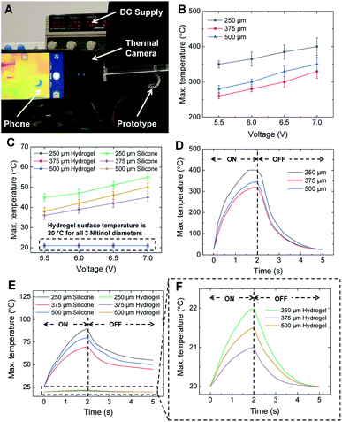
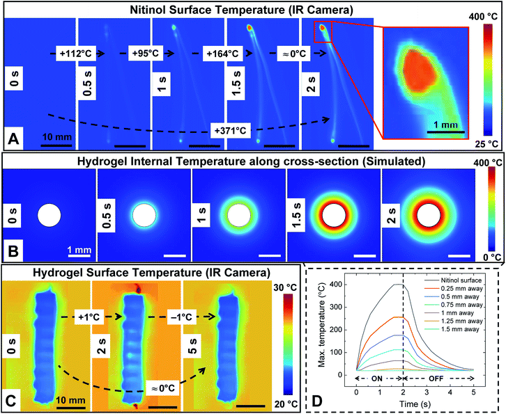
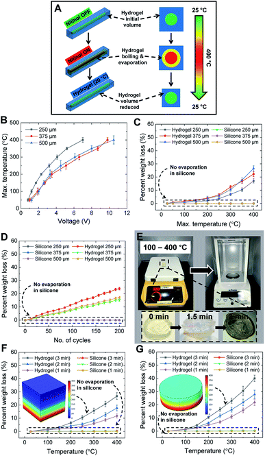
The actuation of Nitinol is due to the Joule heating phenomenon wherein a voltage of 5.5–7 V is supplied to the Nitinol and the temperature of Nitinol is increased. HENA and individual Nitinol wires of different diameters (250, 375, and 500 μm) are fixed at one end and actuated at different voltages (5.5–7 V) to determine the surface temperature of the hydrogel-matrix and individual Nitinol wires throughout its length. Thermal images of the individual Nitinol wire and HENA are acquired (Fig. 3A) and the sequential thermal images during actuation are shown in Fig. 4A and C. The maximum temperature of the Nitinol is observed at the end of the actuation phase (Fig. 3D and 4A), at the junction where the copper wire is twinned to the Nitinol wire. The maximum temperature of individual Nitinol wires (250 μm, 375 μm, and 500 μm), HENA and SENA at different voltages (5.5–7 V) are plotted in Fig. 3B and C, respectively. From Fig. 3B, it is observed that the temperature of the 500 μm diameter Nitinol wire is higher than that of the 375 μm diameter Nitinol wire throughout all voltages (5.5–7 V). This is due to the fact that the 375 μm Nitinol wire is a low temperature alloy (austenite finish temperature = 78 °C) while the 500 μm Nitinol wire is a high temperature alloy (austenite finish temperature = 98 °C). Although the activation power required for the 375 μm Nitinol wire (0.16 W) is less than that required for the 500 μm Nitinol wire (0.24 W), the high temperature alloy is able to achieve a marginally higher temperature (≈10–20 °C) compared to the low temperature alloy when activated at the same voltage (more information is available in the Materials and methods). The silicone elastomer environment surrounding the Nitinol wire dissipated 85% of the heat and had a surface temperature ranging from 35–55 °C, whereas the hydrogel-matrix surrounding the Nitinol wire was able to dissipate 95% of the heat and had a surface temperature of 20 °C in one cycle. The silicone elastomer trapped 78% of the heat from reaching the SENA surface during the actuation phase displaying a surface temperature of 65–90 °C. By contrast, the hydrogel-matrix trapped 94.5% of the heat from reaching the HENA surface during the actuation phase displaying a surface temperature of 21–22 °C. Only 8% and 0.5% of the total heat dissipated in a cycle is dissipated during the recovery phase for the silicone elastomer and hydrogel-matrix, respectively.From Fig. 3B and C, the highest maximum temperature for all Nitinol wire diameters is at 7 V actuation, hence the change in temperature for one cycle is analyzed. The changes in temperature of individual Nitinol wires, HENA and SENA at 7 V for different diameters are shown in Fig. 3D–F. From Fig. 3B and D, the maximum temperature is the highest for the 250 μm Nitinol wire when actuated at 7 V, hence the heat dissipation in the hydrogel-matrix is simulated and shown in Fig. 4B. The change of temperature in the hydrogel-matrix at different points (0.25, 0.5, 0.75, 1, 1.25, and 1.5 mm) away from the Nitinol surface for one cycle is plotted in Fig. 4D. It is observed that more than 60% of the heat from the Nitinol is trapped within 0.5 mm of the hydrogel-matrix, indicating the miniaturizing possibilities of the actuator.
2.3 Self-cooling and dehydration of the hydrogel-matrix
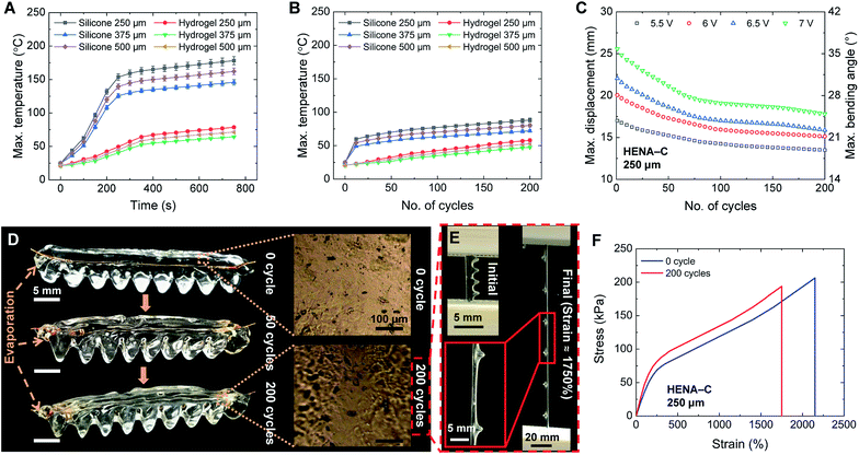
The efficiency of the heat dissipation is observed to decrease in both hydrogel-matrix and silicone elastomer with an increase in the time of exposure to the heat from the Nitinol wire. Due to the antagonistic conformation of the hydrogel to Nitinol, it is necessary to sustain the actuation of Nitinol for the HENA to remain in any of its active conformations. The largest bending angle is achieved when actuated at 7 V, which displays the highest surface temperature. The surface temperature for prolonged actuation of Nitinol at 7 V (Fig. 5A) increased rapidly and traversed 75 °C within 100 s for SENA, whereas HENA required 750 s to do the same. When actuated for a prolonged time (750 s), SENA and HENA dissipated 50% and 81% of the heat, respectively. HENA was able to dissipate 85% of the heat for actuation of 200 cycles at 7 V (Fig. 5B) which is equal to the heat dissipation of SENA in the first cycle, and the heat dissipation dropped further for SENA as the number of cycles increased.We recorded the actuation of HENA-C (250 μm) at different voltages (5.5–7 V) for 200 cycles and acquired the dynamic displacement and bending angle. The displacement and bending angle of HENA-C reduced over the number of cycles at all voltages (5.5–7 V), but the rate of variation is highest at 7 V and least at 5.5 V. HENA-C is unable to return to its initial position due to the loss in elasticity of the encapsulating hydrogel-matrix which causes a reduction in the release of strain energy during its relaxation phase. This trend increased as the number of cycles increased for all voltages (5.5–7 V). The changes in the maximum displacement and maximum bending angle over 200 cycles are determined and shown in Fig. 5C. The maximum bending angle reduced from 21° to 18.5° for 5.5 V, 31.5° to 22° for 6 V, 28° to 21° for 6.5 V, and 35° to 23.5° for 7 V. The maximum bending angle decreased by more than 60% of the total reduction in the first 50 cycles and then stabilized over the next 150 cycles (Fig. 5C). The changes in the structure and surface of the hydrogel-matrix in HENA (250 μm) actuated at 7 V for 0, 50, and 200 cycles are shown in Fig. 5D. We observed a 25% decrease in the volume of the hydrogel-matrix after 200 cycles with negligible change in the length and almost equal change in the width and height of the hydrogel-matrix. The volume of the notches existing on one side of the hydrogel-matrix reduced significantly over 200 cycles. The height of the notches reduced from 4 mm to ≈3 mm and each side (4 mm) of the triangular section also reduced with an area change in the section of ≈30% over 200 cycles giving a visual appearance of large notches. We conducted uniaxial tensile mechanical testing of HENA at 0 cycles and 200 cycles using a universal testing machine (UTM) to determine the difference in stretchability. Both the 0 cycles and 200 cycles samples were elongated at a rate of 5 mm min−1 until failure. The initial and final photos before failure during elongation of the 200 cycles sample is shown in Fig. 5E. The HENA at 0 cycles and 200 cycles achieved a maximum strain of ≈2250% and ≈1750% of its initial length before fracture, respectively (Fig. 5F). HENA at 0 cycles was able to sustain a stress of 206 kPa while HENA at 200 cycles sustained only 194 kPa.
The high heat dissipation capability of the hydrogel-matrix from the Nitinol surface is due to its water content (≈80–90 wt%) at 20–22 °C. During actuation, the hydrogel-matrix proximal to the Nitinol surface is boiled and evaporated resulting in weight loss (Fig. 5D and 6A). The hydrogel-matrix in the HENA is exposed to different temperatures (25–400 °C) for 3 min by actuating all diameters of Nitinol wires (250, 375, and 500 μm). The weight loss was observed to be less than 5% for an actuation temperature below 200 °C. By contrast, it increased exponentially after 200 °C and reached 25% at 400 °C, with the highest weight loss occurring for HENA with the 500 μm Nitinol wire. Although only 25% of the weight is lost in the hydrogel (Fig. 6C), the hydrogel loses its elasticity which reduces its bending performance (Fig. 5C). The weight loss in the hydrogel-matrix for all diameters (250, 375, and 500 μm) of Nitinol over 200 cycles (7 V) of actuation (actuation period of 2 s, recovery period of 3 s) is shown in Fig. 6D. HENA with 500 μm Nitinol wire had the highest weight loss of ≈25% over 200 cycles, HENA with 375 μm Nitinol wire had a weight loss of ≈19% over 200 cycles, and HENA with 250 μm Nitinol wire had a weight loss of ≈18% over 200 cycles. The dehydration kinetics and recoverability of the HENA matrix are crucial for extending its shelf life. Adding water into the HENA matrix and resting for 10–15 min recovered the bending performance (more information is available in the Materials and methods). Actuating HENA according to the 5 s actuation cycle (actuation period of 2 s, recovery period of 3 s) instead of 3 min should let HENA achieve at least 90 cycles without any recovery period before losing 25% weight loss. Different profiles of hydrogel-matrix samples were tested on a hot plate (Fig. 6E), with the bottom surface of the samples in contact with the hot plate at 100–400 °C, while the top surface was measured (IR imaging) to be ≈100–200 °C and the temperature profile of the samples’ cross-sections (simulated) are shown in the inset of Fig. 6F and G. Different profiles of the hydrogel-matrix showed similar weight loss (25%) when subjected to heat (same temperature) from the surface (Fig. 6E and F), while a change in the duration of exposure or thickness of the hydrogel modified the weight loss (Fig. 6F and G).
3 Impending applications
3.1 Cadaveric experiment
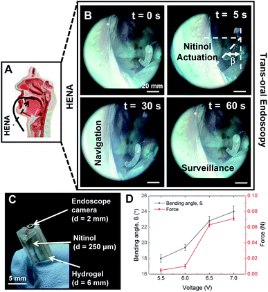
The hydrophilicity of HENA and the retention of large amounts of water aids in the sustained heat dissipation during Nitinol actuation. Given that the bulk matrix is predominantly water (with a large specific heat capacity), it is easier to design for biocompatibility and hence it can potentially be used for safer robot–tissue interactions. Additionally, these matrices are mechanically compliant and thus promote safer interaction with the surrounding tissues. The performance of HENA can be fine-tuned by changing the hydrogel compositions6,16,41 and tailoring the Nitinol thermomechanical modulation to the specific clinical needs. The cadaver is female with no notable existing medical conditions. The cadaver head is separated from the body above the C7 cervical vertebrae. The head is placed supine on the work table and the oral cavity is retained open with retractors. The cadaver is stored in a preservative tub and kept under cold room conditions which do affect the tissue mechanics. The Olive Medical OVS1 Video System Portable Hysteroscopy System (Olive Medical Corporation, UT, USA) together with a 0° and a 30° nasal endoscope was used for imaging in the oral cavity. The cadaver was obtained from MedCure Inc. and is unidentifiable. Taking into account the plasticization of the tissue muscles in a cadaver as compared to a live human experiment, some resistance is expected during the procedure of initial trials performed with our HENA endoscope for transoral navigation. However, a cadaveric experiment shows initial promise and limitations, and challenges that the medical device will encounter during real-time robot–tissue interactions. The HENA endoscope as depicted in Fig. 7A–C was used for trans-oral navigation and surveillance purposes with a bending capability of ≈25°. The maximum force from the HENA endoscope addressed here is 0.07 N (Fig. 7D) which is permissible in the regime of the tissue perforation limit.423.2 Soft robotic gripper
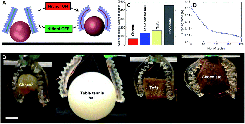
Nitinol wires (diameter, 250 μm) are thermomechanically programmed to a curved conformation (radius of curvature, 20 mm) using a 3D printed mold similar to the actuation of fabrication of HENA-C. Two HENA-C are assembled on the same plane such that the actuation is antagonistic to each other. Both are actuated simultaneously at the same or different voltages to facilitate gripping of different morphological 3D objects of different weights as shown in Fig. 8C.Two HENA (Nitinol, 250 μm) actuators are actuated simultaneously antagonistic to each other to perform a gripping action on 3D objects (Fig. 8A). The gripper (≈2 g) can handle a wide range of 3D objects such as cheese, a table tennis ball, tofu, and chocolate (Fig. 8B) and is capable of lifting up objects weighing 450% of its own weight (Fig. 8C). The gripper is able to grip an object with a rigid uniform morphology such as a table tennis ball and objects with deformable irregular morphologies such as cheese, tofu, and chocolate. The hydrogel-matrix maintains the surface temperature at 20–22 °C during Nitinol actuation for the gripping action and enables the gripper to handle cheese and chocolate that melt at temperatures much below the Nitinol actuation temperature. The gripper demonstrated that it was able to handle a table tennis ball which is 45 times larger in volume than the gripper. The gripping force of the soft robotic gripper varied over 200 cycles of utilization (Fig. 8D). The gripping force was observed to be ≈0.16 N during the first cycle of actuation and reduced to ≈0.11 N accounting to a ≈31% decrease in the gripping force. The gripping force decreased by ≈60% of its total reduction in the first 50 cycles from ≈0.16 N to ≈0.12 N and then stabilized over the next 150 cycles with a reduction in gripping force of only ≈0.01 N (Fig. 8D).
4 Conclusions
In summary, in this article, we encapsulate Nitinol shape-memory-alloy wire in a hydrogel-matrix to fabricate a lightweight (≈1 g), self-cooling actuator (HENA) for soft robots. HENA is able to make a smooth transition between the compliant unactuated and stiff actuated state in a 5 s cycle period performing a bending angle up to 35°. The hydrogel-matrix in HENA trapped the heat emitted by Nitinol due to its high temperature (200–400 °C), maintaining its surface temperature in the range 20–22 °C. HENA trapped 14.5% more heat from the Nitinol than SENA during the actuation phase and dissipated 10% more heat than SENA in one cycle. HENA dissipated 7.5% more heat from the Nitinol than SENA when actuated for 200 cycles, and 31% more heat than SENA when actuated for a prolonged time of 750 s. HENA actuated for 200 cycles was able to retain ≈70% of its bending performance and only lost ≈25% of its initial weight over the 200 cycles of actuation. The bending performance retention of HENA was even higher (≈73–78%) when actuated at lower voltages (5.5–6.5 V). HENA also had ≈1750% stretchability after 200 cycles of actuation. HENA carrying an endoscope camera performed a bending angle 25° and was tested in a cadaver for trans-oral navigation. Hence, HENA demonstrated promising biomedical applicability without damaging tissues due to its self-cooling capability and the generation of less force. Two HENA actuated simultaneously antagonistic to each other demonstrated a custom made soft robotic gripper which is able to carry 3D objects (low melting point foods) of different morphologies weighing up to 9.2 g. The soft robotic gripper was able to retain ≈69% of its gripping force over 200 cycles. HENA once commercialized poses promising avenues for food processing industries and bio-medical sectors for much safer human–robot interactions. In the near future, we intend to scale down the HENA endoscope to aid in transnasal navigation and localized drug delivery and also to develop bioinspired and biomimetic HENA soft robots to move in extreme environments.5 Materials and methods
5.1 Biocompatible hydrogels
Hydrogels are in the family of polymeric materials where the bulk of the matrix consists of water (typically 80–90% wt). The polymers cross-link with each other to form a network and water molecules ingress into the network, swelling the gel.6,40 The hydrophilicity of the polymers enables the retention of large amounts of water which aids in the heat dissipation during Nitinol actuation given the large specific heat capacity of water. Given that the bulk matrix is predominantly water, it is easier to design for biocompatibility and hence it potentially can be used for safer robot–tissue interactions. Additionally, these matrices are mechanically compliant and promote safer interaction with the surrounding tissues. The mechanics of these hydrogels can be tuned and optimized by changing the compositions in the matrix,6,16,41 tailoring to the specific clinical needs.Here, an alginate gel with G blocks of ionic polymeric chains cross-links via Ca2+ ions (red circles in Fig. 1C) within a polyacrylamide gel for which N,N0-methylene-bis-acrylamide (MBA) (blue squares) acts as a covalent cross-linker. Finally, the alginate–polyacrylamide hybrid gel is formed, where both alginate and polyacrylamide networks are integrated through a strong covalent cross-linker (black triangle): carboxyl groups for the alginate gel and amine groups for the polyacrylamide gel are demonstrated (Fig. 1A–C).
5.2 Experimental procedure for fabrication of the hydrogel
The biocompatible hydrogel depicted in this article is comprised of two different polymer networks (covalently crosslinked acrylamide and ionically crosslinked sodium alginate) 40 and is prepared with tailored ingredients and concentrations. The one-pot method was used to prepare the stock solutions, followed by 4 hours of ultrasonication (Sonica 5200, Sonica Inc., Japan) with continuous stirring and a 24 hour rest period for crosslinking. Chemicals used to produce the hydrogel are sodium alginate (SA, Sigma-Aldrich; ≤15.5%); acrylamide (AA, Sigma-Aldrich; ≥99.9%); N,N′-methylene-bis-acrylamide (MBA, Sigma-Aldrich; ≈99%); and 2-hydroxy-4′-(2-hydroxyethoxy)-2-methylpropiophenone (photo-initiator or PI, Sigma-Aldrich; ≥97.5%). The obtained solution is cured using a da Vinci UV curing chamber (XYZprinting, Inc.) with UV LED (λ = 375–405 nm) and rested for 24 hours before use. The concentrations of all ingredients are given in Table S1 (ESI†).5.3 Dehydration kinetics and recoverability of the hydrogel
The dehydration kinetics and recoverability are key factors to understand the preservation and shelf life of hydrogels. Dehydration kinetics refers to the mechanism in which the water content of the hydrogel decreases at a particular temperature over a period of time. The standard condition of storage for a hydrogel is at 21 °C. Fig. 6A–G show the percentage weight loss gravimetrically. Sodium alginate hydrogels were observed to dehydrate completely within days, which leads to recovery and reservation being crucial to extend their shelf life. Adding an initial amount of water and allowing them to rest for hours recovered samples of completely dehydrated hydrogels. This shows promising recoverability values of the hydrogels after they have been fully dehydrated. Measurements of the recovered samples were compared with original measurements of the sample.Microscopic analysis (AFM/SEM) of the different hydrogel layers will be investigated in the future to further improve the recoverability procedure to ensure equal water diffusion throughout the hydrogel. Recoverability of the hydrogel thus promises that hydrogel soft robots can be stored and reused, increasing their potential to be commercialized. However, future research will inculcate freezing the hydrogels at low temperatures to retain their water content during storage to prevent dehydration.
5.4 Nitinol
Nitinol wires are obtained under the trade name FLEXINOL®(DYNALLOY, Inc., CA, USA). The 250 μm and 375 μm diameter Nitinol wires are low temperature alloys with an austenite finish temperature of 78 °C and a martensite finish temperature of 42 °C, while the 500 μm diameter Nitinol wires are low temperature alloys with an austenite finish temperature of 98 °C and a martensite finish temperature of 62 °C. The power required to achieve the austenite finish temperature was 0.08 W for the 250 μm Nitinol wire, 0.16 W for the 375 μm Nitinol wire, and 0.24 W for the 500 μm Nitinol wire. All diameters (250, 375, and 500 μm) of Nitinol wires have a shape setting temperature at 300 °C. When the wire is fixed in a particular conformation and heated to the set temperature, the austenite phase remembers this particular configuration. At room temperature, Nitinol is in the martensite phase and is flexible. Through Joule heating, the temperature is raised and the martensite fraction converts to the austenite phase, reverting to the remembered configuration. The encasing spring and 3D printed elastomer is stiffer than the martensite Nitinol and defines the total curvature. During the austenite transformation, Nitinol is stiffer than the spring and 3D printed elastomer, which exerts a force to change the total curvature. Three different diameters of Nitinol wires (length, 40 mm) are used in the characterisation: 250, 375, and 500 μm. All the Nitinol wires are connected to copper wires (length, 300 mm) which transmit signals from an external DC supply for actuation.5.5 Thermomechanical programming of nitinol
Thermomechanical programming was done on the Nitinol wire to remember a curved conformation (radius of curvature, 20 mm) and a straight conformation. We 3D printed (Nobel 1.0, XYZ Printing, Inc., Taiwan) two different molds, one having a curved channel (radius of curvature, 20 mm) and another with a straight channel where the wire was fixated during the thermomechanical programming process. The Nitinol is to be heated at 300 °C in order to program and hence an SLA based urethane acrylate and acrylic monomer 3D printed mold was used instead of the conventional 3D printing mold. By Joule heating, the Nitinol was heated at 300 °C for 5 to 7 seconds followed by quenching in water (20 °C) for 3 to 5 seconds. This procedure was repeated for 7 to 10 cycles.5.6 Hydrogel-matrix encapsulated nitinol actuator (HENA)
Two designs of HENA (HENA-C and HENA-S) are fabricated and tested. The fabrication of HENA-C is shown in Fig. 1D. The Nitinol is thermomechanically programmed straight for HENA-S and is pre-strained in a 3D printed (Nobel 1.0, XYZ Printing, Inc., Taiwan) mold with a curved channel (radius of curvature, 20 mm). The pre-strained Nitinol is secured at the centre of the 3D printed (LulzBot, Aleph Objects, Inc., CO, USA) mold with a curved channel (radius of curvature, 20 mm) with a slot (4 mm × 4 mm × 40 mm) where the hydrogel is filled and cured. The design has rigged edges (notches) on the outer side to facilitate larger bending. The Nitinol is thermomechanically programmed curved (radius of curvature, 20 mm) for HENA-C and is pre-strained in a 3D printed (Nobel 1.0, XYZ Printing, Inc., Taiwan) mold with a straight channel. The pre-strained Nitinol is secured at the center of the 3D printed (LulzBot, Aleph Objects, Inc., CO, USA) mold with a straight channel with a slot (4 mm × 4 mm × 40 mm) where the hydrogel is filled and cured. The design has 9 complete notches with triangular (equilateral) sections with each side of length 4 mm. Hence, the longer width of the hydrogel-matrix will be 8 mm and the shorter width will be 4 mm.The Nitinol in the HENA is actuated using an external DC supply. The activation and deactivation were done manually by controlling the voltage and the current passed to the HENA. Current is passed to the HENA to actuate for 2 s and then it is deactivated for a 3 s recovery period completing a cycle. The actuation of HENA is shown in Fig. 1G.
5.7 Silicone elastomer nitinol actuator (SENA)
For preparing SENA, we first mixed Ecoflex-0030 A and Ecoflex-0030 B (Smooth-On, Inc., PA, USA) in the ratio (w/w) 1![[thin space (1/6-em)]](https://www.rsc.org/images/entities/char_2009.gif) :
:![[thin space (1/6-em)]](https://www.rsc.org/images/entities/char_2009.gif) 1 and kept the mixture inside a vacuum desiccator to prevent air bubbles in the silicone gel. We poured the mixture onto the mold and waited for at least four hours for the silicone rubber to cure with the pre-strained Nitinol for SENA finalization. The mold was designed with the 3D CAD design software (SolidWorks, Dassault Systemes®, France) and then 3D printed with a LulzBot 3D printer (Aleph Objects, Inc., CO, USA).
1 and kept the mixture inside a vacuum desiccator to prevent air bubbles in the silicone gel. We poured the mixture onto the mold and waited for at least four hours for the silicone rubber to cure with the pre-strained Nitinol for SENA finalization. The mold was designed with the 3D CAD design software (SolidWorks, Dassault Systemes®, France) and then 3D printed with a LulzBot 3D printer (Aleph Objects, Inc., CO, USA).
5.8 Cadaver
The cadaver is female with no notable existing medical conditions. The cadaver head is separated from the body above the C7 cervical vertebrae. The head is placed supine on the work table and the oral cavity is retained open with retractors. The cadaver is stored in a preservative tub and kept under cold room conditions which do affect the tissue mechanics. The Olive Medical OVS1 Video System Portable Hysteroscopy System (Olive Medical Corporation, UT, USA) together with a 0° and a 30° nasal endoscope was used for imaging in the oral cavity. The cadaver was obtained from MedCure Inc. and is unidentifiable. Taking into account the plasticization of the tissue muscles in a cadaver as compared to a live human experiment, some resistance is expected during the procedure of initial trials performed with our HENA endoscope for transoral navigation. However, a cadaveric experiment shows initial promise and limitations, and challenges that the medical device will encounter during real-time robot–tissue interactions.5.9 Performance of bending
HENA and individual Nitinol wires of different diameters (250, 375, and 500 μm) are fixed at one end and actuated at different voltages (5.5–7 V) to determine the displacement of the other end of the Nitinol wire. A video camera is fixed normal to the motion of the Nitinol wires, and the actuation video is recorded. The start and the end position of the actuation cycles are used to determine the maximum displacement and maximum deflection angle. Both ends of the Nitinol are tracked dynamically during actuation using Tracker 5.0 (Douglas Brown©) and the relative angle between the two points can then be determined. The displacement magnitudes (δ) and bending angles (β) are calculated by selecting a point where the vector of the tip and base intersects (Fig. 3B). All the samples are tested for 5 repetitions and the average values with error bars are plotted in Fig. 2C–G. The HENA % bending displacement (α) to its length is given by,
 | (1) |
5.10 Blocking force during actuation
The blocking force generated at the tip of both HENA-C and HENA-S is determined using a Nano17-E Transducer (ATI Industrial Automation, Inc., NC, USA) by allowing the tip of the prototype to contact the transducer normally during actuation (5.5–7 V). The maximum tip force data are captured for all diameters (250 μm, 375 μm, and 500 μm) of Nitinol wires in both HENA-C and HENA-S at different voltages (5.5 V, 6 V, 6.5 V, and 7 V) for 5 repetitions. The maximum force from the HENA is 0.095 N, which is not sufficient to perforate tissues.425.11 Thermal analysis
HENA and individual Nitinol wires of different diameters (250, 375, and 500 μm) are fixed at one end and actuated at different voltages (5.5–7 V) to determine the surface temperature of the hydrogel-matrix and individual Nitinol wires throughout its length. An infrared camera, FLIR ONE Pro (FLIR®Systems, Inc., OR, USA), is fixed normal to the motion of the HENA and Nitinol wires, and the change in surface temperature during the course of actuation and recovery is recorded. All the samples are tested for 5 repetitions and the average values with error bars are plotted in Fig. 3B–F, 5A and B.The simulation of the heat dissipation along the cross-section of the hydrogel-matrix in HENA shown in Fig. 4B and D is done using the time-dependent equation solver in COMSOL Multiphysics® (COMSOL, Inc., MA, USA),
 | (2) |
 is the temperature gradient, ρ is the density of the hydrogel matrix, dz is the thickness of the cross-section, ∇T is the temperature change in the hydrogel matrix, Q is the heat energy, Cp is the specific heat capacity at constant pressure, and q is given as,
| q = −dzk∇T | (3) |
5.12 Scanning electron microscopy
The swollen hydrogels were rapidly frozen at −80 °C and then dried in a freeze-dryer (Virtis freeze mobile, Virtis Co., Gardiner, USA), and the surface morphology of the hydrogel structure used in HENA, shown in Fig. 1D was investigated using SEM (FEI Quanta 600 and FESEM; JEOL-JSM-6610LV) operating at 15.0 kV for low and high resolution imaging.5.13 Optical microscopy
The optical microscopy images are shown in Fig. 5C, was taken with an IX51 microscope (Olympus, Japan) equipped with a DP72 digital imaging system (Olympus) and Olympus LUC Plan FLN 20×/0.45 and 10×/0.30 objective lens (Olympus, Japan) to show the changes in the surface of the hydrogel-matrix of non-actuated HENA and the hydrogel-matrix of HENA actuated for 200 cycles.5.14 Tensile testing
The hydrogel-matrix from HENA at 0 and 200 cycles is tested using the uniaxial tensile test in Instron 5543 (Illinois Tool Works Inc., USA) with a 500 N load cell at a rate of 5 mm min−1. The tensile test optical photos and results are shown in Fig. 5E and F respectively.5.15 Soft robotic gripper
Nitinol wires (diameter, 250 μm) are thermomechanically programmed to a curved conformation (radius of curvature, 20 mm) using a 3D printed mold similar to the actuation of fabrication of HENA-C. Two HENA-C are assembled on the same plane such that the actuation is antagonistic to each other. Both are actuated simultaneously at different voltages to facilitate gripping of different morphological 3D objects of different weights as shown in Fig. 8C. The gripping force is determined using a Nano17-E Transducer (ATI Industrial Automation, Inc., USA).Conflicts of interest
There are no conflicts to declare.Acknowledgements
The authors would like to thank the Department of Otolaryngology, at the National University Hospital, Khoo Teck Puat Advanced Surgery Training Centre for assistance with the cadaver experiments. The authors would like to acknowledge Dr Fanfan Fu and Mr Karthik Prathaban for helping with the scanning electron microscopy and optical microscopy, respectively. This work is supported by the NMRC Bedside & Bench under grant R-397-000-245-511, NUSRI China Jiangsu Provincial Grant BK20150386 and BE2016077 awarded to Dr Hongliang Ren.References
- D. Rus and M. T. Tolley, Nature, 2015, 521, 467 CrossRef CAS.
- H. Banerjee, Z. T. H. Tse and H. Ren, Int. J. Robot. Autom., 2018, 33, 69–80 Search PubMed.
- S. I. Rich, R. J. Wood and C. Majidi, Nat. Electron., 2018, 1, 102 CrossRef.
- C. Walsh, Nat. Rev. Mater., 2018, 3, 78 CrossRef.
- M. Cianchetti, T. Ranzani, G. Gerboni, T. Nanayakkara, K. Althoefer, P. Dasgupta and A. Menciassi, Soft Robot., 2014, 1, 122–131 CrossRef.
- H. Banerjee and H. Ren, Soft Robot., 2017, 4, 191–201 CrossRef.
- R. K. Katzschmann, J. DelPreto, R. MacCurdy and D. Rus, Science Robotics, 2018, 3, eaar3449 CrossRef.
- A. D. Marchese, C. D. Onal and D. Rus, Soft Robot., 2014, 1, 75–87 CrossRef.
- M. A. McEvoy and N. Correll, Science, 2015, 347, 1261689 CrossRef CAS PubMed.
- S. C. Goldstein, J. D. Campbell and T. C. Mowry, Computer, 2005, 38, 99–101 Search PubMed.
- O. R. Bilal, A. Foehr and C. Daraio, Adv. Mater., 2017, 29, 1700628 CrossRef.
- R. F. Shepherd, F. Ilievski, W. Choi, S. A. Morin, A. A. Stokes, A. D. Mazzeo, X. Chen, M. Wang and G. M. Whitesides, Proc. Natl. Acad. Sci. U. S. A., 2011, 108, 20400–20403 CrossRef CAS.
- D. C. Nemir, Am. Control Conf., 1989, 1989, 2374–2376 Search PubMed.
- H. Rodrigue, W. Wang, D.-R. Kim and S.-H. Ahn, Compos. Struct., 2017, 176, 398–406 CrossRef.
- X. Huang, K. Kumar, M. K. Jawed, A. Mohammadi Nasab, Z. Ye, W. Shan and C. Majidi, Adv. Mater. Technol., 2019, 1800540 CrossRef.
- H. Banerjee, O. Y. W. Aaron, B. S. Yeow and H. Ren, 2018 3rd International Conference on Advanced Robotics and Mechatronics (ICARM), 2018, pp. 630–635 Search PubMed.
- V. Bundhoo, E. Haslam, B. Birch and E. J. Park, Robotica, 2009, 27, 131–146 CrossRef.
- A. Hadi, H. Akbari, B. Tarvirdizadeh and K. Alipour, Sens. Actuators, A, 2016, 243, 90–102 CrossRef CAS.
- Y. Fu, X. Li, H. Liu, Z. Liang and X. Ma, IEEE International Conference on Robotics and Biomimetics, 2006. ROBIO’06, 2006, pp. 1594–1599 Search PubMed.
- T. Fukuda, S. Guo, K. Kosuge, F. Arai, M. Negoro and K. Nakabayashi, Robotics and Automation, 1994. Proceedings., 1994 IEEE International Conference on, 1994, pp. 2290–2295 Search PubMed.
- M. S. Kalairaj and W. M. Huang, MATEC Web of Conferences, 2017, p. 01010 Search PubMed.
- M. S. Kalairaj, W. M. Huang and F. Klanner, Electrical Engineering and Automation: Proceedings of the International Conference on Electrical Engineering and Automation (EEA2016), 2017, pp. 996–1004 Search PubMed.
- A. Esmaeli, Majlesi Journal of Electrical Engineering, 2014, 8(2), 25–31 Search PubMed.
- T. Mineta, T. Mitsui, Y. Watanabe, S. Kobayashi, Y. Haga and M. Esashi, Sens. Actuators, A, 2002, 97, 632–637 CrossRef.
- N. V. Datla and P. Hutapea, J. Med. Dev., 2015, 9, 041005 CrossRef.
- A. S. Veeramani, G. D. Buckner, S. B. Owen, R. C. Cook and G. Bolotin, Smart Mater. Struct., 2008, 17, 015037 CrossRef.
- S. S. Cheng and J. P. Desai, Robotics and Automation (ICRA), 2015 IEEE International Conference on, 2015, pp. 2580–2585 Search PubMed.
- N. Lewis, A. York and S. Seelecke, Smart Mater. Struct., 2013, 22, 094012 CrossRef.
- Y. Luo, T. Takagi, S. Maruyama and M. Yamada, J. Intell. Mater. Syst. Struct., 2000, 11, 503–511 CrossRef CAS.
- L.-x. Zhang, G.-x. Hu and Z.-g. Wang, Int. J. Therm. Sci., 2008, 47, 306–314 CrossRef.
- R. A. Russell and R. B. Gorbet, Proceedings of 1995 IEEE international conference on robotics and automation, 1995, pp. 2299–2304 Search PubMed.
- Y. Kim, S. S. Cheng, A. Ecins, C. Fermüller, K. P. Westlake and J. P. Desai, ASME 2014 Dynamic Systems and Control Conference, 2014, pp. V001T04A006–V001T04A006 Search PubMed.
- C. S. Loh, H. Yokoi and T. Arai, Int. J. Adv. Robot. Syst., 2006, 3, 42 CrossRef.
- A. Pathak, D. Brei and J. Luntz, Student's papers, ed. A. Pathak, Mechanical Engineering, University of Michigan, 2008, vol. 2250, pp. 48109–2126 Search PubMed.
- S. S. Cheng, Y. Kim and J. P. Desai, IEEE Trans. Robot., 2017, 33, 986–993 Search PubMed.
- W. R. Illeperuma, P. Rothemund, Z. Suo and J. J. Vlassak, ACS Appl. Mater. Interfaces, 2016, 8, 2071–2077 CrossRef CAS.
- H. Banerjee, M. Suhail and H. Ren, Biomimetics, 2018, 3, 15 CrossRef.
- J. D. Madden, N. A. Vandesteeg, P. A. Anquetil, P. G. Madden, A. Takshi, R. Z. Pytel, S. R. Lafontaine, P. A. Wieringa and I. W. Hunter, IEEE J. Oceanic Eng., 2004, 29, 706–728 CrossRef.
- M. Boyvat, J.-S. Koh and R. J. Wood, Science Robotics, 2017, 2, eaan1544 CrossRef.
- J.-Y. Sun, X. Zhao, W. R. Illeperuma, O. Chaudhuri, K. H. Oh, D. J. Mooney, J. J. Vlassak and Z. Suo, Nature, 2012, 489, 133 CrossRef CAS.
- H. Yuk, S. Lin, C. Ma, M. Takaffoli, N. X. Fang and X. Zhao, Nat. Commun., 2017, 8, 14230 CrossRef CAS.
- F. Carter, T. Frank, P. Davies and A. Cuschieri, Surg. Endosc., 2000, 14, 783–786 CrossRef CAS.
Footnotes |
| † Electronic supplementary information (ESI) available. See DOI: 10.1039/c9ra05360c |
| ‡ These authors contributed equally to this work. |
| This journal is © The Royal Society of Chemistry 2019 |

