 Open Access Article
Creative Commons Attribution 3.0 Unported Licence
In situ addition of graphitic carbon into a NiCo2O4/CoO composite: enhanced catalysis toward the oxygen evolution reaction†
Srinivasa N.a,
Shreenivasa L.a,
Prashanth S. Adarakatti b,
Jack P. Hughescd,
Samuel J. Rowley-Neale
 cd,
Craig E. Banks
 *cd and
Ashoka S.
 *a
*a
aDepartment of Chemistry, School of Engineering, Dayananda Sagar University, Bangalore, India. E-mail: ashok022@gmail.com; Tel: +91 8049092924
bPG Department of Chemistry, KLE's PC Jabin Science College, Hubballi, India
cFaculty of Science and Engineering, Manchester Metropolitan University, Chester Street, Manchester M1 5GD, UK. E-mail: c.banks@mmu.ac.uk; S.Rowley-Neale@mmu.ac.uk; Web: http://craigbanksresearch.com Fax: +44 (0)1612476831; Tel: +44 (0)1612471196
dManchester Fuel Cell Innovation Centre, Manchester Metropolitan University, Chester Street, Manchester M1 5GD, UK
First published on 12th August 2019
Abstract
We present a rapid, environmentally benign one-pot synthesis technique for the production of a NiCo2O4/CoO and graphite composite that demonstrates efficient electrocatalysis towards the Oxygen Evolution Reaction (OER), in 1.0 M KOH. The NiCo2O4/CoO/graphitic carbon composite that displayed optimal OER catalysis was synthesized by nitrate decomposition in the presence of citric acid (synthesized glycine and sucrose variants displayed inferior electro kinetics towards the OER). Screen-printed electrodes modified with ca. 530 μg cm−2 of the citric acid NiCo2O4/CoO/graphite variant displayed remarkable OER catalysis with an overpotential (η) of +323 mV (vs. RHE) (recorded at 10 mA cm−2), which is superior to that of IrO2 (340 mV) and RuO2 (350 mV). The composite also exhibited a large achievable current density of 77 mA cm−2 (at +1.5 V (vs. RHE)), a high O2 turnover frequency of 1.53 × 10⁻² s−1 and good stability over the course of 500 repeat cycles. Clearly, the NiCo2O4/CoO composite has the potential to replace precious metal based catalysts as the anodic material within electrolysers, thereby providing a reduction in the associated costs of hydrogen production via water splitting.
1 Introduction
The implementation of hydrogen as a clean fuel source has prompted the research and development of novel materials explored towards electrolytic water splitting, where proficient electrocatalysts will increase efficiency and economic viability of hydrogen production. The efficiency of overall water splitting is limited by the sluggish kinetics of the oxygen evolution reaction (OER), which is the anodic reaction within an electrolyser. The OER is a four step electron transfer (4OH− → O2 + 2H2O + 4e−).1,2 Iridium and ruthenium oxide based catalysts2–4 are widely considered the optimal performing electrocatalysts towards the OER. However, the practical applications of these oxide catalysts are limited owing to their scarcity, high cost and catalytic instability. This has created an impetus to develop efficient, low cost and abundant catalysts for the OER.5Table 1 summarizes studies that have explored cobalt and nickel based spinel oxides towards the OER.6 Good long-term stability in an alkaline medium and proficient electrochemical performance towards the OER make cobalt and nickel based spinel oxides interesting alternatives to precious metal based materials. However, their poor electrical conductivity hinders their large-scale application within industry. In order to mitigate poor electrical conductivity the NiCo2O4 is typically gelled with metals,7–9 and carbon based materials, such as carbon nanotubes,10,11 carbon fibers, carbon nanowires,12–14 graphene,15 and graphene aerogels.16–19 The gelling of graphene with NiCo2O4 uses harsh chemicals and usually takes prolonged durations of time, potentially several hours or days.20 Despite progress in the development of NiCo2O4 based catalysts, the preparation of cheap and environmentally benign materials with good electronic transport properties, high mechanical stability and good electro-kinetic ability towards the OER remains a challenge.
| Catalyst | Method of preparation and conditions used | Overpotential (mV) | Tafel slope (mV dec−1) | Ref. |
|---|---|---|---|---|
| a CNT – carbon nanotube; CFP – carbon fiber paper; NS – nano sheets; NW – nanowire; NN – nano needles; CC – carbon cloth; CFC – carbon fiber cloth. | ||||
| NiCo2O4/CNT | Hydrothermal synthesis at 100 °C10 h followed by calcination 400 °C/2 h | 340 | 133 | 22 |
| NiCo2O4-NN | Hydrothermal at 90 °C/10 h and annealed in air at 320 °C/2 h | 365 | 292 | 28 |
| NiCo2O4-NS | Hydrothermal at 90 °C/10 h and annealed in air at 320 °C/2 h | 415 | 393 | 28 |
| NiCo2O4/VN800 Vulcan XC-72 | Precipitation annealed 200 °C/3 h | 385 | 75.7 | 30 |
| NiCo2S4 NS/CC | Hydrothermal at 120 °C/8 h followed by annealed at 450 °C/2 h | 260 | 123 | 31 |
| Ni0.33Co0.67MoS4/CFC | Hydrothermal at 110 °C/6 h | 283 | 68.8 | 32 |
| NiCo2O4/CoO/graphitic carbon composite | Nitrate decomposition method at 500 °C/3 minutes | 323 | 118 | This work |
To address these limitations when using NiCo2O4 based catalysts we describe a short (3 minute) one-pot wet chemical synthesis technique for a NiCo2O4/CoO composite that has varied amounts of incorporated graphitic carbon. The quantity of the graphitic carbon present in the NiCo2O4/CoO has been varied in situ using citric acid, sucrose and glycine precursors during the course of the reaction. The graphitic carbon in the proposed composite acts like 2D graphene in terms of providing an anchoring framework and enhancing the conductivity. The prepared NiCo2O4/CoO/graphitic carbon composite is thoroughly characterized by powder XRD, FTIR and SEM. The graphitic carbon rich NiCo2O4/CoO composite is then fabricated upon the surface of screen-printed electrodes (SPE) which are explored towards the OER in 1 M KOH. The NiCo2O4/CoO SPEs deliver an impressively low over potential of 323 mV at a current density of 10 mA cm−2, which is superior to the overpotentials reported in previous studies using traditional catalysts; IrO2 (340 mV) and RuO2 (350 mV)21 and Au/NiCo2O4 nano rod array (360 mV).22
2. Experimental section
2.1. Chemicals
Analytical reagent grade nickel nitrate hexahydrate (Ni(NO3)2·6H2O), cobalt nitrate hexahydrate (Co(NO3)2·6H2O), citric acid (C6H8O7), sucrose (C12H22O11), glycine (C2H5NO2), and potassium hydroxide (KOH) were purchased from SD Fine Chemicals Ltd. India and used as received without any further purification.2.2. NiCo2O4/CoO/graphitic compound synthesis
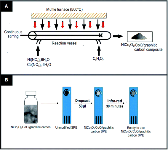
The NiCo2O4/CoO/graphitic carbon composites were prepared using facile one-pot nitrate decomposition in the presence of citric acid, sucrose and glycine, Fig. 1(A) depicts the one-pot synthesis. In a typical synthesis, 0.859 mM of nickel nitrate hexahydrate (0.25 g) and 1.71 mmol of cobalt nitrate hexahydrate (0.50 g) were dissolved in 7 ml of deionized water and stirred until the metal nitrates dissolved completely. To the resulting solution, 1.432 mmol of citric acid (0.300 g) was added and continually stirred to get a uniform solution. Then, the precursor solution was kept in a preheated muffle furnace maintained at 500 °C. The reaction was rested to retain graphitic carbon in the prepared NiCo2O4/CoO composite by taking out the reaction vessel after 3 minutes from the preheated muffle furnace. Finally, the obtained powder NiCo2O4/CoO/graphitic carbon composite was crushed in a mortar and pestle and used for further study. Similarly, sucrose and glycine have been used to retain different amounts of graphitic carbon in the NiCo2O4/CoO.2.3 Characterization equipment
The powder X-ray diffraction (XRD) pattern of the synthesized NiCo2O4/CoO/graphitic carbon composite was recorded using PANalytical X'pert PRO X-ray diffractometer with a graphite monochromatized CuKα radiation source. The Fourier-transform infrared (FTIR) spectrum of the NiCo2O4/CoO/graphitic carbon composite was recorded using IS5-800 Fourier transform infrared Nicolet spectrometer in the range of 400–4000 cm−1 in the transmittance mode. The morphology of the NiCo2O4/CoO/graphitic carbon composite was studied using a JEOL-5600LV scanning electron microscope (SEM). Transmission electron microscopy (TEM) images were obtained using a 200 kV primary beam under conventional bright-field conditions. The sample was dispersed onto a holey-carbon film supported on a 300 mesh Cu TEM grid. The electrochemical studies were carried out using a SP150 Biologic potentiostat.2.4. Electrode preparation
The fabrication of the screen-printed electrodes (SPE's) utilized within this study is illustrated in Fig. 1(B), where 3 mg of the prepared NiCo2O4/CoO/ graphitic carbon composite was dispersed in 4 ml of deionized water under sonication for 30 minutes to get a homogenous dispersion. 50 μL of the resultant homogenous dispersion was drop casted onto an SPE and subjected to drying under infra-red light for 30 minutes. Thus, the electrocatalytic performance towards the OER of each modified SPE was ready to be assessed. Note the surface coverage of catalyst upon the SPE was ca. 530 μg cm−2.2.5. Electrochemical measurements
Cyclic voltammetric (CV) and linear sweep voltammetric (LSV) measurements were carried out using a three-electrode system where the NiCo2O4/CoO/graphitic carbon composite SPEs, nickel and Ag/AgCl electrodes were used as working, counter and reference electrodes, respectively. The catalytic activity of the NiCo2O4/CoO/graphitic carbon composite towards the oxygen evolution reaction (OER) was studied in 1 M KOH, of pH = 14, in the potential range 0–1.5 V at a scan rate of 20 mV s−1.3. Result and discussion
3.1. Physicochemical characterization of the NiCo2O4/CoO composites
The TEM images of the NiCo2O4/CoO nano-composite prepared by using citric acid are shown in Fig. 2(A and B), wherein the NiCo2O4/CoO nanoparticles (crystalline particles) are uniformly distributed and covered by a graphitic carbon network (amorphous region). The TEM images of the NiCo2O4/CoO nano-composite prepared by using sucrose (Fig. 2(C and D)) reveal the presence of randomly distributed agglomerated particles. The TEM images of the NiCo2O4/CoO nano-composite prepared by using glycine exhibit highly agglomerated particles with irregular morphology (Fig. 2(E and F)). The interplanar spacing's are highlighted in Fig. 2(B and D) where the spacing's of 0.14, 0.20, 0.24 and 0.28 nm are indexed to the (440), (400), (220) and (311) crystal planes of NiCo2O4, respectively.23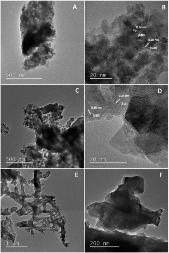 | ||
| Fig. 2 The TEM images of the NiCo2O4/CoO composite prepared at 500 °C/3 minutes by using (A and B) citric acid, (C and D) sucrose and (E and F) glycine. | ||
The crystallographic information of the synthesized product was analyzed using powder XRD measurements. The NiCo2O4/CoO composite with varied amounts of graphitic carbon is prepared using citric acid, sucrose and glycine where XRD patterns of each are presented in Fig. 3. The composites prepared using citric acid, sucrose and glycine exhibit peaks at 31.1°, 36.59°, 44.62°, 59.14° and 65.15° corresponding to the (220), (311), (400), (511), and (440) crystalline planes of the spinel cubic structure of NiCo2O4 with Fd![[3 with combining macron]](https://www.rsc.org/images/entities/char_0033_0304.gif) m space group (JCDS 73-1702). Additionally, the reflection peaks at 42.85° and 62.2°, indicated by *, show the presence of CoO. Fig. 4 indicates that the prepared product is composed of the NiCo2O4/CoO composite. FTIR analysis of the NiCo2O4/CoO composite can be seen in Fig. 4, it reveals the presence of graphitic carbon in the prepared NiCo2O4/CoO composite. The NiCo2O4/CoO composite prepared by using citric acid, sucrose and glycine, exhibit characteristic peaks at 557 cm−1 and 649 cm−1 assigned to the intrinsic metal–oxygen stretching vibrations in NiCo2O4/CoO composites.24 The peaks at 557 cm−1 and 649 cm−1 are assigned to the Co–O vibrational mode at the octahedral site and the Ni–O vibration mode at the tetrahedral site, respectively.25 Additionally, the NiCo2O4/CoO composite prepared using citric acid and sucrose exhibits a well-defined D band at 1385 cm−1, and a G band at 1573 cm−1 corresponding to the disordered carbon and ordered graphitic carbon, respectively.26 Furthermore, the composite prepared using citric acid possesses a higher quantity of graphitic carbon, confirmed with the intensity of the peak at 1385 cm−1, when compared to the composite prepared using sucrose. The NiCo2O4/CoO composite prepared using glycine does not exhibit peaks at 1385 cm−1 and 1573 cm−1 indicating the absence of carbon. Thus, the amount of the graphitic carbon in the prepared NiCo2O4/CoO composites varied in the order of citric acid > sucrose > glycine.
m space group (JCDS 73-1702). Additionally, the reflection peaks at 42.85° and 62.2°, indicated by *, show the presence of CoO. Fig. 4 indicates that the prepared product is composed of the NiCo2O4/CoO composite. FTIR analysis of the NiCo2O4/CoO composite can be seen in Fig. 4, it reveals the presence of graphitic carbon in the prepared NiCo2O4/CoO composite. The NiCo2O4/CoO composite prepared by using citric acid, sucrose and glycine, exhibit characteristic peaks at 557 cm−1 and 649 cm−1 assigned to the intrinsic metal–oxygen stretching vibrations in NiCo2O4/CoO composites.24 The peaks at 557 cm−1 and 649 cm−1 are assigned to the Co–O vibrational mode at the octahedral site and the Ni–O vibration mode at the tetrahedral site, respectively.25 Additionally, the NiCo2O4/CoO composite prepared using citric acid and sucrose exhibits a well-defined D band at 1385 cm−1, and a G band at 1573 cm−1 corresponding to the disordered carbon and ordered graphitic carbon, respectively.26 Furthermore, the composite prepared using citric acid possesses a higher quantity of graphitic carbon, confirmed with the intensity of the peak at 1385 cm−1, when compared to the composite prepared using sucrose. The NiCo2O4/CoO composite prepared using glycine does not exhibit peaks at 1385 cm−1 and 1573 cm−1 indicating the absence of carbon. Thus, the amount of the graphitic carbon in the prepared NiCo2O4/CoO composites varied in the order of citric acid > sucrose > glycine.
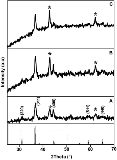 | ||
| Fig. 3 Powder XRD patterns of the NiCo2O4/CoO composite prepared at 500 °C/3 minutes by using (A) citric acid, (B) sucrose and (C) glycine. | ||
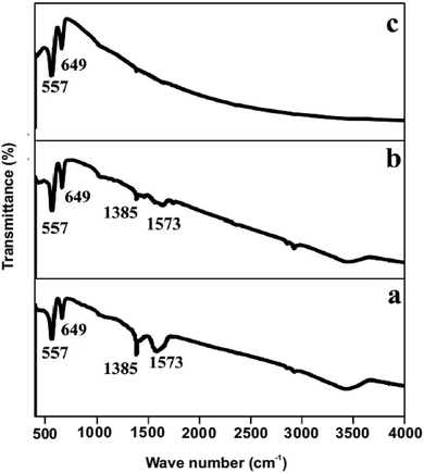 | ||
| Fig. 4 FTIR spectrum of the NiCo2O4/CoO composite prepared at 500 °C/3 minutes by using (a) citric acid, (b) sucrose and (c) glycine. | ||
The catalytic activity of the synthesized NiCo2O4/CoO/graphitic carbon composite material could be largely dependent on the morphology. Hence, ESI Fig. S1† displays the SEM images of the prepared composite revealing that the particles are aggregated and thus appear like ledges with randomly distributed grains, large lateral dimensions and thin flat surfaces, where, a higher number of edge and active sites will result in greater OER performance. Careful observation reveals that the NiCo2O4/CoO/graphitic carbon composite prepared from glycine exhibits larger sized ledges compared to the composite prepared from citric acid and sucrose. Thus, it is expected that the composite prepared using citric acid and sucrose will exhibit better OER performance owing to the presence of graphitic carbon, increasing the number of electrical pathways, and high lateral size with thin and flat surfaces.
3.2. Application of the NiCo2O4/CoO composite SPE's towards the OER
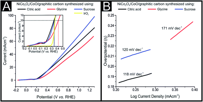
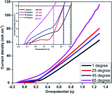
The NiCo2O4/CoO/graphitic composites prepared using citric acid, sucrose and glycine were explored towards the OER. The electrocatalytic performance of the NiCo2O4/CoO/graphitic carbon composites were further examined using linear sweep voltammetry (LSV) in a solution of 1 M KOH with the obtained LSVs being displayed in Fig. 5(A). The LSV curves of the NiCo2O4/CoO/graphitic carbon composites prepared using citric acid and sucrose, in Fig. 5(A), indicate the presence of an oxidation peak at +0.13 V vs. RHE (inset of Fig. 5(A)). The observed peak at +0.13 V is a result of the oxidation of Co3+ to Co4+.27 This oxidation of Co3+ to Co4+ suggests that the Co3+ present at the octahedral site is responsible for the onset of the OER.28 No oxidation peak is observed for the NiCo2O4/CoO/graphitic carbon composite prepared using glycine, moreover, the mechanism for the OER using this composite is not clear and requires further study. The dramatic increase in current density after +0.14 V vs. RHE in all three cases demonstrates the onset of the OER. The inset of Fig. 5(A) shows the overpotential required to produce 10 mA cm−2 for the NiCo2O4/CoO/graphitic carbon composites prepared from citric acid, sucrose and glycine, which were found to be 323 mV, 344 mV and 408 mV, respectively. The overpotential observed for the composite prepared from citric acid is less electropositive compared to that of the composite prepared from sucrose and glycine, indicative of a lower activation energy for the OER to progress. The results presented above suggest that the presence of graphitic carbon enhances the conductivity of the electrolyte and thereby enhances the charge and mass transfer during the OER at the surface of the metal oxide.29 The overpotential required to produce a current density of 10 mA cm−2 exhibited by the NiCo2O4/CoO/graphitic (323 mV) is less electropositive than the overpotential required by traditionally employed electrocatalysts IrO2 (340 mV) and RuO2 (350 mV) and Au/NiCo2O4 nanorod array (360 mV). The LSV for an IrO2 can be seen within the inset of Fig. 5. Additionally, of all the studies reported in Table 1 the NiCo2O4/CoO/graphitic composite prepared using citric acid, displayed the best performing electrochemical activity in terms of OER onset potential, in fact, it displayed the smallest overpotential that the authors of this manuscript have found to date within literature.22,28,30–32 The citric acid NiCo2O4/CoO composite is therefore a viable alternative to precious metals as the anodic material within water electrolysers. It is important to note that whilst the citric acid NiCo2O4/CoO composite variant displayed the lowest overpotential post 0.45 V (vs. RHE) the NiCo2O4/CoO composite produced using sucrose displayed the largest achievable current density.The effect of temperature on the electrocatalytic behavior of the NiCo2O4/CoO/graphitic carbon composites on OER performance is displayed in Fig. 6. Using η and the obtained Tafel values as a function of temperature, the catalytic performance of the composite prepared with citric acid within a varied temperature range was measured towards the OER in 1 M KOH solution using LSV and the corresponding anodic current response. The overpotential required to produce 10 mA cm−2 of current density at temperatures of 274, 300, 320 and 340 K was found to be 405 mV, 329 mV, 326 and 205 mV, respectively, suggesting the OER performance increased monotonically with temperature.33 Thus, at higher temperatures enhanced OER activity is observed, accordingly, the NiCo2O4/CoO/graphitic carbon composite is potentially a good catalyst with the utilization of the infrared range of the solar spectrum for water oxidation.
The OER kinetics of the NiCo2O4/CoO/graphitic carbon composites derived from citric acid, sucrose and glycine were assessed by Tafel analysis, as shown in Fig. 5(B), Tafel analysis demonstrates the co-relation between over potential (η and current density (log![[thin space (1/6-em)]](https://www.rsc.org/images/entities/char_2009.gif) J) wherein it is used to deduce the reaction mechanism by which the OER progresses. The value of the Tafel slope was determined from the polarization curves and the corresponding Tafel values of the composites derived from citric acid, sucrose and glycine were 118, 120 and 171 mV dec−1, respectively. Analysis of the Tafel values can be utilized to determine the rate determining step for the OER reaction mechanism (mechanism displayed below).21,34–38
J) wherein it is used to deduce the reaction mechanism by which the OER progresses. The value of the Tafel slope was determined from the polarization curves and the corresponding Tafel values of the composites derived from citric acid, sucrose and glycine were 118, 120 and 171 mV dec−1, respectively. Analysis of the Tafel values can be utilized to determine the rate determining step for the OER reaction mechanism (mechanism displayed below).21,34–38
| M + OH− → e− + MOH(adsorption) | (1) |
| MOH + OH− → e− + H2O + MO | (2) |
| MO + OH− → e− + MOOH | (3) |
| MOOH + OH− → H2O + e− + MOO | (4) |
| MOO → O2 + M | (5) |
In order to understand the excellent OER electrocatalytic performance of the NiCo2O4/CoO composite derived from citric acid, electrochemical impedance spectra (EIS) were recorded between the frequency range 0.01 Hz and 100 kHz. The electrochemical performance of the composite is affected by charge transfer resistance (Rct) at the electrode/electrolyte interface. Thus, EIS measurements were carried out to investigate the Rct. Fig. 7 depicts the Nyquist plots of fresh NiCo2O4/CoO/graphitic carbon composites and the measured impedance spectra were analyzed using Zsimpwin software by fitting with an electrical equivalent circuit. An equivalent circuit is composed of Rct, constant phase element Q, and Warburg impedance (W) corresponds to different electrochemical processes that occur at the electrode/electrolyte interface. The Nyquist plot consists of an intercept and straight sloping line at high and low frequency regions corresponding to the Rct and W respectively.40 The NiCo2O4/CoO/graphitic carbon composite derived from citric acid exhibits charge transfer resistance (Ω) of ca. 920.34 Ω while ca. 1242.18 Ω and ca. 1353.94 Ω are observed for composites derived from sucrose and glycine, respectively. The higher conductivity/lower resistivity of the composite derived from citric acid is consistent with the LSV results presented in Fig. 4(A) and suggest the sucrose NiCo2O4/CoO/graphitic carbon composite is the optimal electrocatalyst.
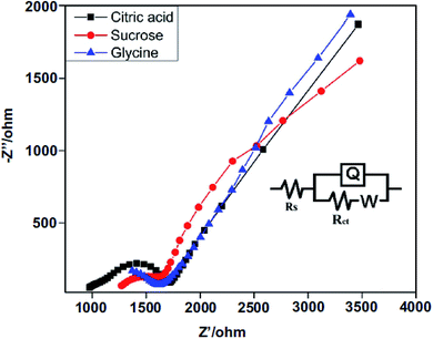 | ||
| Fig. 7 Electrochemical impedance Nyquist plots of fresh NiCo2O4/CoO/graphitic carbon composite in 1 M KOH solution, frequency range 0.01 Hz to 100 kHz; inset: equivalent circuit. | ||
The stability and durability of a catalyst are important considerations if they are to be utilized within an industrial application. The stability and durability of the NiCo2O4/CoO/graphitic carbon composites were studied using 1000 repeated LSVs at a scan rate of 20 mV s−1 in 1.0 M KOH, where the retention of the current density after 100, 200, 500 and 1000 cycles is summarized in Table 2. Table 2 shows that the NiCo2O4/CoO/graphitic carbon composite derived from citric acid displays an excellent stability comparable to the composite derived from sucrose and glycine. It is observed that the NiCo2O4/CoO/graphitic carbon composites derived from citric acid and sucrose exhibit good current retention of about 91.8 and 90.9% after 200 cycles, respectively. Furthermore, current density retention of 63.2 and 61.6% has been observed after 200 cycles for the NiCo2O4/CoO/graphitic carbon composites derived from citric acid and sucrose, respectively, whereas, a 56% current density retention for the composite derived from glycine is indicative of poorer stability. Thus, stability for the NiCo2O4/CoO/ graphitic carbon composite varied in the order of citric acid > sucrose > glycine. In addition to the cyclic stability test, chronoamperometry was performed on the composites derived from citric acid, sucrose and glycine, carried out at an applied potential of 0.7 V vs. Ag/AgCl in 1 M KOH for a period of 10 hours, the corresponding results are shown in ESI Fig. S2.† The current density for all composites increases initially and then becomes almost stable after 2 hours. After 10 hours of cycling, the NiCo2O4/CoO/graphitic carbon composite derived from citric acid exhibits a current density retention of 93%, demonstrating excellent stability. Under the same conditions, the composites derived from sucrose and glycine display a current density retention of 90.71%, and 90% respectively. Thus, the stability of the proposed electrodes herein exceeds that of the benchmarked IrO2 and RuO2 based electrodes previously reported within literature.41–44
| NiCo2O4/CoO/graphitic carbon composite | Current density retention after 100 cycles | Current density retention after 200 cycles | Current density retention after 500 cycles | Current density retention after 1000 cycles |
|---|---|---|---|---|
| a Value not recorded. | ||||
| Citric acid | 99.2% | 91.8% | 63.2% | 38.40% |
| Sucrose | 98.6% | 90.9% | 61.6% | 33.8% |
| Glycine | 84.8% | 56.6% | — | — |
The number of moles of O2 generated per second per mole by the NiCo2O4/CoO/graphitic carbon composite at η10, is expressed using turn over frequency, calculated using current density obtained from LSV.45 The value of TOF for the NiCo2O4 catalyst is found to be 1.53 × 10⁻² s−1, which is close to the TOF value for NiCo2O4/NiO (1.4 × 10⁻² s−1)46 and superior to that of the TOF value reported for NiFe2O4 (5.74 × 10⁻⁴ s−1) and MxNi1−xFe2O4 (0.7–1.87 × 10⁻⁴ s−1).34 This indicates that the NiCo2O4/CoO/graphitic carbon composite can serve as an efficient and stable catalyst for water oxidation.
4. Conclusions
A rapid one-pot synthesis has been proposed to prepare NiCo2O4/CoO composites with varied additions of graphitic carbon using citric acid, sucrose and glycine. The NiCo2O4/CoO/graphitic carbon composite prepared with citric acid exhibits the optimal overpotential (η10), Tafel slope and TOF with values of 323 mV, 118 mV dec−1 and 1.53 × 10⁻² s−1, respectively. The excellent electrochemical performance of the composite towards the OER could be related to the synergetic effect of graphitic carbon and the large lateral dimensions with thin and flat surface morphology. Moreover, the electrocatalytic performance towards the OER exhibited by the NiCo2O4/CoO/graphitic carbon composite prepared with citric acid is superior to the performance reported in previous studies using highly regarded electrocatalysts IrO2 and RuO2. It follows that the composite derived from citric acid is a potentially excellent electrocatalyst for overall water splitting applications given its significant electro-kinetic activity towards the OER. Adoption of the proposed method to explore other non-precious metal oxides to enhance the OER performance is underway.Conflicts of interest
There are no conflicts to declare.Acknowledgements
This work was financially supported by the Science and Engineering Research Board (SERB) under the scheme early carrier research (ECR/2017/000743). Funding from the Engineering and Physical Sciences Research Council (Reference: EP/P007767/1 and EP/N0011877/1), British Council Institutional Grant Link (No. 172726574) is acknowledged. The Manchester Fuel Cell Innovation Centre is funded by the European Regional Development Fund.References
- J. Vilana, D. Escalera-López, E. Gómez and E. Vallés, J. Alloys Compd., 2015, 646, 669–674 CrossRef CAS
.
- Y. Lee, J. Suntivich, K. J. May, E. E. Perry and Y. Shao-Horn, J. Phys. Chem. Lett., 2012, 3, 399–404 CrossRef CAS PubMed
.
- W. Zhong, Z. Lin, S. Feng, D. Wang, S. Shen, Q. Zhang, L. Gu, Z. Wang and B. Fang, Nanoscale, 2019, 11, 4407–4413 RSC
.
- X. Lu and C. Zhao, Nat. Commun., 2015, 6, 6616 CrossRef CAS PubMed
.
- Y. Zhang, X. Wang, F. Luo, Y. Tan, L. Zeng, B. Fang and A. Liu, Appl. Catal., B, 2019, 256, 117852 CrossRef CAS
.
- Z. Xu, H. Pan, Y. Lin, Z. Yang, J. Wang and Y. Gong, J. Mater. Chem. A, 2018, 6, 18641–18648 RSC
.
- X. Yang, L. Tian, M. He and X. Chen, Nano Lett., 2015, 15, 6015–6021 CrossRef PubMed
.
- Y. Liu, S. Shen, J. Zhang, W. Zhong and X. Huang, Appl. Surf. Sci., 2019, 478, 762–769 CrossRef CAS
.
- A. Aijaz, J. Masa, C. Rösler, W. Xia, P. Weide, A. J. R. Botz, R. A. Fischer, W. Schuhmann and M. Muhler, Angew. Chem., Int. Ed., 2016, 55, 4087–4091 CrossRef CAS PubMed
.
- D. C. Higgins, D. Meza and Z. Chen, J. Phys. Chem. C, 2010, 114, 21982–21988 CrossRef CAS
.
- H. Cheng, Y.-Z. Su, P.-Y. Kuang, G.-F. Chen and Z.-Q. Liu, J. Mater. Chem. A, 2015, 3, 19314–19321 RSC
.
- T. Y. Ma, S. Dai, M. Jaroniec and S. Z. Qiao, J. Am. Chem. Soc., 2014, 136, 13925–13931 CrossRef CAS PubMed
.
- J. Yin, P. Zhou, L. An, L. Huang, C. Shao, J. Wan, H. Liu and P. Xi, Nanoscale, 2016, 8, 1390–1400 RSC
.
- S. Deshagani, X. Liu, B. Wu and M. Deepa, Nanoscale, 2019, 11, 2742–2756 RSC
.
- J.-Y. Choi, D. Higgins and Z. Chen, J. Electrochem. Soc., 2011, 159, B86–B89 CrossRef
.
- S. Chakrabarty, A. Mukherjee and S. Basu, ACS Sustainable Chem. Eng., 2018, 6, 5238–5247 CrossRef CAS
.
- Y. Gong, Z. Xu, H. Pan, Y. Lin, Z. Yang and J. Wang, J. Mater. Chem. A, 2018, 6, 12506–12514 RSC
.
- Y. Gong, Z. Yang, Y. Lin, J. Wang, H. Pan and Z. Xu, J. Mater. Chem. A, 2018, 6, 16950–16958 RSC
.
- Y. Gong, Z. Xu, H. Pan, Y. Lin, Z. Yang and X. Du, J. Mater. Chem. A, 2018, 6, 5098–5106 RSC
.
- S. T. Aruna and A. S. Mukasyan, Curr. Opin. Solid State Mater. Sci., 2008, 12, 44–50 CrossRef CAS
.
- M. Tahir, L. Pan, R. Zhang, Y.-C. Wang, G. Shen, I. Aslam, M. A. Qadeer, N. Mahmood, W. Xi, L. Wang, X. Zhang and J.-J. Zou, ACS Energy Lett., 2017, 2, 2177–2182 CrossRef CAS
.
- Z. Ma, H. Fu, C. Gu, Y. Huang, S. Hu, Q. Li and H. Wang, RSC Adv., 2018, 8, 28209–28215 RSC
.
- W. Wang, Z. Li, A. Meng and Q. Li, J. Solid State Electrochem., 2019, 23, 635–644 CrossRef CAS
.
- K. Pandi, M. Sivakumar, S.-M. Chen, Y.-H. Cheng and T.-W. Chen, Int. J. Electrochem. Sci., 2018, 13, 1227–1240 CrossRef CAS
.
- M. Kebir, A. Boudjemaa and K. Bachari, Mater. Sci. Semicond. Process., 2015, 39, 300–307 CrossRef CAS
.
- S. V. Devaguptapu, S. Hwang, S. Karakalos, S. Zhao, S. Gupta, D. Su, H. Xu and G. Wu, ACS Appl. Mater. Interfaces, 2017, 9, 44567–44578 CrossRef CAS PubMed
.
- R. Zhang, Y.-C. Zhang, L. Pan, G.-Q. Shen, N. Mahmood, Y.-H. Ma, Y. Shi, W. Jia, l. Wang, X. Zhang, W. Xu and J.-J. Zou, ACS Catal., 2018, 8, 3803–3811 CrossRef CAS
.
- H. Shi and G. Zhao, J. Phys. Chem. C, 2014, 118, 25939–25946 CrossRef CAS
.
- P. S. Adarakatti, V. K. Gangaiah, C. E. Banks and A. Siddaramanna, J. Mater. Sci., 2018, 53, 4961–4973 CrossRef CAS
.
- Z. Zheng, X. Du, Y. Wang, C. M. Li and T. Qi, ACS Sustainable Chem. Eng., 2018, 6, 11473–11479 CrossRef CAS
.
- S. Hyun and S. Shanmugam, ACS Omega, 2018, 3, 8621–8630 CrossRef CAS
.
- L. Hang, T. Zhang, Y. Sun, D. Men, X. Lyu, Q. Zhang, W. Cai and Y. Li, J. Mater. Chem. A, 2018, 6, 19555–19562 RSC
.
- G. Zhu, X. Xie, X. Li, Y. Liu, X. Shen, K. Xu and S. Chen, ACS Appl. Mater. Interfaces, 2018, 10, 19258–19270 CrossRef CAS PubMed
.
- V. Maruthapandian, M. Mathankumar, V. Saraswathy, B. Subramanian and S. Muralidharan, ACS Appl. Mater. Interfaces, 2017, 9, 13132–13141 CrossRef CAS PubMed
.
- Z. Chen, C. X. Kronawitter, Y.-W. Yeh, X. Yang, P. P. Zhao, N. Yao and B. E. Koel, J. Mater. Chem. A, 2017, 5, 842–850 RSC
.
- Z. Chen, B. Zhao, Y.-C. He, H.-R. Wen, X.-Z. Fu, R. Sun and C.-P. Wong, Mater. Chem. Front., 2018, 2, 1155–1164 RSC
.
- C. Ray, S. C. Lee, B. Jin, A. Kundu, J. H. Park and S. C. Jun, ACS Sustainable Chem. Eng., 2018, 6, 6146–6156 CrossRef CAS
.
- Q. Zhang, D. Yan, Z. Nie, X. Qiu, S. Wang, J. Yuan, D. Su, G. Wang and Z. Wu, ACS Appl. Energy Mater., 2018, 1, 571–579 CrossRef CAS
.
- C. Zhu, N. Sheng and T. Akiyama, RSC Adv., 2015, 5, 21066–21073 RSC
.
- H. Rong, T. Chen, R. Shi, Y. Zhang and Z. Wang, ACS Omega, 2018, 3, 5634–5642 CrossRef CAS
.
- L. Gong, D. Ren, Y. Deng and B. S. Yeo, ACS Appl. Mater. Interfaces, 2016, 8, 15985–15990 CrossRef CAS
.
- D. Chen, C. Chen, Z. M. Baiyee, Z. Shao and F. Ciucci, Chem. Rev., 2015, 115, 9869–9921 CrossRef CAS PubMed
.
- T. Audichon, T. W. Napporn, C. Canaff, C. Morais, C. Comminges and B. K. Kokoh, J. Phys. Chem. C, 2016, 120, 2562–2573 CrossRef CAS
.
- T. Reier, M. Oezaslan and P. Strasser, ACS Catal., 2012, 2, 1765–1772 CrossRef CAS
.
- C.-H. Kuo, I. M. Mosa, A. S. Poyraz, S. Biswas, A. M. El-Sawy, W. Song, Z. Luo, S.-Y. Chen, J. F. Rusling, J. He and S. L. Suib, ACS Catal., 2015, 5, 1693–1699 CrossRef CAS
.
- C. Mahala and M. Basu, ACS Omega, 2017, 2, 7559–7567 CrossRef CAS
.
Footnote |
| † Electronic supplementary information (ESI) available. See DOI: 10.1039/c9ra05195c |
| This journal is © The Royal Society of Chemistry 2019 |

