
 Open Access Article
 This Open Access Article is licensed under a Creative Commons Attribution-Non Commercial 3.0 Unported Licence
Retracted Article: The influence of gradient and porous configurations on the microwave absorbing performance of multilayered graphene/thermoplastic polyurethane composite foams
Chaozhi Wang ,
Jiang Li* and
Shaoyun Guo
,
Jiang Li* and
Shaoyun Guo
The State Key Laboratory of Polymer Materials Engineering, Polymer Research Institute of Sichuan University, Chengdu 610065, China. E-mail: li_jiang@scu.edu.cn
First published on 15th July 2019
Abstract
Single-layer graphene/TPU composite foams with different graphene content were prepared through a thermally induced phase separation (TIPS) process. Multilayer graphene/TPU composite foams were fabricated by bonding single-layer foams together. The arrangement of single-layer graphene/TPU composite foams in different orders could realize a gradient distribution of the graphene to endow the multilayer foams with good impedance matching characteristics. Facile regulation of the effective absorption bandwidth (EB) value and minimum reflection loss (RLmin) have been realized by adjusting the thickness and layer number or altering the combinatorial mode of single-layer foams with different graphene contents to endow these multilayered composite foams with optimal microwave-absorbing (MA) properties. In addition, the mechanism of microwave dissipation by gradient multilayers and porous structures has been elucidated. The EB values of the multilayer foams were all wider than those of their corresponding single-layer foams with the same graphene content and multilayer foams displayed much lower RLmin than single-layer foams. Among all the multilayer foams, 2L graphene/TPU composite foams with a thickness of 5 mm exhibit the widest EB value of 9.9 GHz and the lower RLmin (−36.7 dB) while 5L graphene/TPU composite foams with a thickness of only 2.5 mm show the lowest RLmin of −43.7 dB and wider EB values (5.3 GHz).
1. Introduction
The serious electromagnetic (EM) irradiation caused by the widespread application of wireless telecommunication devices has concerned the whole society, due to it has danger to human health as well as issues with communication security.1–8 Carbon materials, such as carbon nanotubes,9–12 carbon fibers13–16 and graphene,4,6,17–22 possess good electrical conductivity and dielectric performance, and thereby are usually employed in polymer matrices to fabricate microwave absorbing materials (MAMs), owing to their superior properties including mechanical flexibility, light weight, corrosion resistance and excellent processability.23–25 After bringing porous structures into polymeric MAMs, such materials can be further processed into composite foams.26–29 In contrast with the solid MAMs, porous materials not only show stronger microwave-absorbing (MA) capacity to eliminate the secondary pollution resulting from EM reflection, but possess lower density to reduce the fabrication cost. More importantly, high flexibility due to foaming broadens their application fields.30–33In the fabrication of polymeric MAMs, a high content of absorbents is generally required to obtain a sufficient MA capacity, inevitably increasing the viscosity of polymer solutions or melts, leading to great difficulties in process.34–36 Hence, multilayer structures were applied to design MAMs to solve this problem, and the results proved that the MA ability could be significantly promoted by the enhanced multiple reflections on the internal layering interfaces.37–45
Due to their flexibility in design, stronger MA ability and wider absorption band, multilayered polymeric composites were developed mainly for substituting ordinary single-layer MAMs. As is well-known, uniform dispersion of absorbent in the polymer matrix is commonly desirable in the fabrication of single-layer MAMs. However, for multilayered MAMs, an inhomogeneous dispersion of absorbents is generally requisite for the purpose of reducing the reflection of microwave on the surface of MAMs and obtaining the matching of wave impedances of adjacent layers.44,46–48 Therefore, multilayered composites with gradient dispersion of absorbents have gradually become the focus of research.25,47,49–51 Nevertheless, challenges still remain in the process of fabricating multilayered composites from single-layered materials. For example, numerous ways of permutation and combination for the single-layered components make it difficult to carry out systematic research of multilayered composites. Furthermore, optimization of layer number and thickness of monolayer components to obtain optimal MA performance has been rarely studied. Based on these, it is very interesting to combine gradient structure with porous structures, carry out a systematic study on the MA properties of multilayered composites and provide meritorious results for fabricating lightweight and well-performing MAMs.
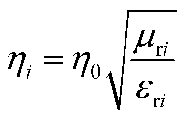
It is known that a well-performing MAM should possess two characteristics: impedance matching and strong attenuation capacity.52–54 In other words, higher characteristic impedance ηr and larger attenuation constant α bring about strong microwave absorption (reflection loss, RL) and a wide effective bandwidth (EB, RL < −10 dB, for 90% energy absorbed).55 A lower minimum RL (RLmin) or a wider EB signifies an excellent MA property. The characteristic impedance
 | (1) |
 | (2) |
![[thin space (1/6-em)]](https://www.rsc.org/images/entities/char_2009.gif) δ.33,35,53,56,57 Unfortunately, characteristic impedance and attenuation constant are inconsistent with the dependence of dielectric constant and dielectric loss. How to balance the relationship between characteristic impedance and attenuation constant has become a major problem to be solved in the manufacture of efficient MAMs.
δ.33,35,53,56,57 Unfortunately, characteristic impedance and attenuation constant are inconsistent with the dependence of dielectric constant and dielectric loss. How to balance the relationship between characteristic impedance and attenuation constant has become a major problem to be solved in the manufacture of efficient MAMs.
In this work, the balance between characteristic impedance and attenuation constant were adjusted through controlling the absorbent content gradient distribution in the multilayered structure and selectively distributing absorbents on the cell walls, to fabricate a high-performance MAM. To accomplish this, we first fabricated various single-layer polymer-based composite foams with different absorbent content. In our another research,33 we found that graphene/thermoplastic polyurethane foams could be fabricated by means of phase separation, and the acquired samples possessed similar porosity, low density and good flexibility, which could assist us in implementing our assumption of designing multilayered composites with porous structure. Inspired by the above, we fabricated multilayered graphene/TPU composite foams in this research by bonding single-layer graphene/TPU composite foams face to face, and systematically investigated the effect of gradient and porous structure on their MA properties. The obtained results indicated that the gradient and porous structures played a momentous role in enhancing the MA performance of multilayered composites. The layered interface of multilayered structure facilitates the dissipation of EM energy inside the MAMs. Moreover, optimization of layer number and thickness of monolayer components can endow these multilayered composite foams with the optimal MA property. More importantly, low-density porous graphene/TPU composite foams can be used as lightweight MAMs.
2. Experimental section
2.1 Materials
A polyester-based TPU elastomer (Elastogran S85A) was obtained from BASF group (Germany). Graphene (XTG-P-0762) were supplied by the Deyang Carbonene Co. Ltd (China). N,N′-Dimethyl formamide (DMF) and 1,4-dioxane were purchased from Kelong Reagent Co. Ltd (China). All of the chemical reagents were analytically pure and used without further purification.2.2 Specimen preparation
In a typical process, different amounts of graphene (1 g, 1.5 g, 2 g, 2.5 g, 3 g, 3.5 g, 4 g) were dispersed in abundant DMF (700 mL) with the help of ultrasonication for 40 min (1000 W). The as-obtained graphene suspensions were transferred into seven identical round-bottomed flasks and TPU pellets (30 g) were added under vigorous stirring at 60 °C for 6 h, respectively. The resultant solution was integrated with excess deionized water, the precipitate (graphene/TPU composites) obtained after filtration was dried at 80 °C for 48 h to wipe off the epibiotic solvent. Afterwards, graphene/TPU composite foams were obtained by thermally induced phase separation (TIPS) process.58–67 The prepared graphene/TPU composites were dissolved in 1,4-dioxane and stirred for 5 h at 60 °C. The dispersed solution was poured into an undefiled metal mold with a length and width of 200 mm and then placed it in a low temperature test chamber at a constant temperature of −60 °C for 1 h. The frozen mixture was then transferred into a vacuum freeze dryer (LGJ-10FD, Yaxing Instrument Science and Technology Development Co., Ltd.) for 36 h at 0 °C. The resultant single-layer graphene/TPU composite foams were then dried at 80 °C for 24 h to remove the residual 1,4-dioxane. The gradient graphene content multilayer graphene/TPU composite foams were obtained by bonding a plurality of single-layer samples of different graphene content with commercial glue. The density, graphene content, electrical conductivity, foam ratio and porosity of single-layer graphene/TPU composite foams are presented in Table 1| Sample | Density (g cm−3) | Graphene content (vol%) | Conductivity (S cm−1) | Foam ratio | Porosity |
|---|---|---|---|---|---|
| S-1 | 0.17 | 1.3 | 2.6 × 10⁻¹¹ | 5.8 | 83% |
| S-2 | 0.17 | 2.1 | 3.4 × 10⁻⁷ | 6.0 | 83% |
| S-3 | 0.16 | 2.7 | 2.8 × 10⁻⁶ | 6.2 | 84% |
| S-4 | 0.16 | 3.3 | 10.2 × 10⁻⁵ | 6.2 | 84% |
| S-5 | 0.15 | 3.8 | 4.8 × 10⁻⁴ | 6.1 | 84% |
| S-6 | 0.15 | 4.6 | 1.5 × 10⁻³ | 6.3 | 84% |
| S-7 | 0.15 | 5.0 | 1.8 × 10⁻⁴ | 6.3 | 84% |
As shown in Table 1, from sample S-1 to sample S-7, the graphene content increased from 1.3 to 5.0 vol%. When the graphene content increased from 4.6 to 5.0 vol%, the conductivity began to decline. As the graphene content further increases, the graphene sheets will be agglomerated in the TPU matrix, which will greatly destroy the constructed three-dimensional conductive network structure shown in Fig. 3 and 6. What's worse, larger graphene content will reduce the volume fraction of TPU matrix and affect the formation and growth of cells, which are very unfavorable for constructing elastic foam with excellent mechanical properties. Thus, the graphene content was limited to 5 vol%.
2.3 Characterization and testing
The morphology of samples was observed by using scanning electron microscopy (SEM, JEOL JSM-5900LV) under an accelerating voltage of 20 kV. The samples were cryo-fractured in liquid nitrogen, and the fractured surfaces were coated with a layer of gold in a vacuum chamber prior to the visualization by SEM.The expansion ratio ϕ of the foams was calculated using eqn (3).68
 | (3) |
The porosity P of single-layer foams can be obtained by eqn (4).69
 | (4) |
The electrical resistivities of S-1, S-2, S-3, S-4, S-5, S-6 and S-7 were obtained using a programmable insulation resistance tester (YD9820A). The sizes of all samples were 10 mm in length (l), 10 mm in width (w) and 2 mm in thickness (t). A constant voltage of 1 V was applied to the samples unless otherwise specified. The electrical conductivity, σ, was calculated by the following equation,
 | (5) |
The electromagnetic parameters, complex relative permittivity (εr = ε′ − jε′′) and permeability (μr = μ′ − jμ′′) of seven single-layer graphene/TPU composite foams with different graphene content, which were processed into a concentric annular shape with an outer diameter of 7 mm and an inner diameter of 3.04 mm, were measured by a vector network analyzer using the coaxial-line method (N5230A, Agilent Technologies Co., LTD) in the range of 2–18 GHz.
3. Results and discussion
3.1 Transmission line theory
Fig. 1 shows a multilayer model containing n layers of different materials while a metal plate is served as its reflective backing. The parameters di is the thickness of the ith layer, ηr represents the complex intrinsic impedance of the ith layer and γi denotes the propagation coefficient of the ith layer (i = 1, 2, 3, … n). ε0 and μ0 are the permittivity and permeability of the free space, respectively.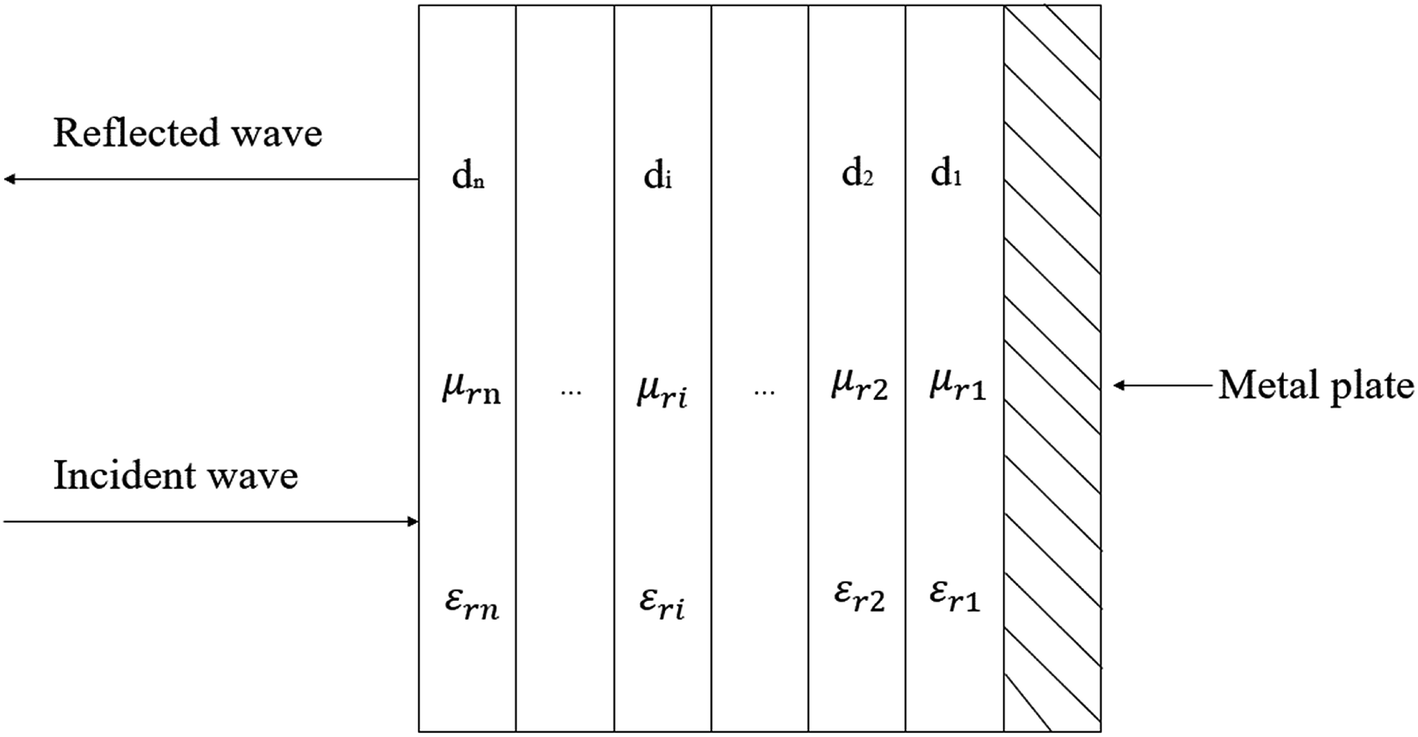 | ||
| Fig. 1 Schematic of a multilayer model with a normally incident wave (di, εri, and μri are the thickness, complex permittivity and permeability of the ith layer, respectively). | ||
According to the transmission-line theory,38,70 the wave impedance, Zi, of the i th layer can be calculated by this equation:
 | (6) |
 | (7) |
 | (8) |
|
Z1 = η1tanh(γ1d1)
| (9) |
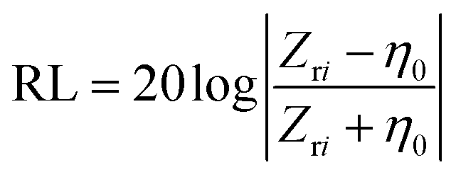
The reflection loss (RL) of the incident microwave can be calculated using the equation as follows:
 | (10) |
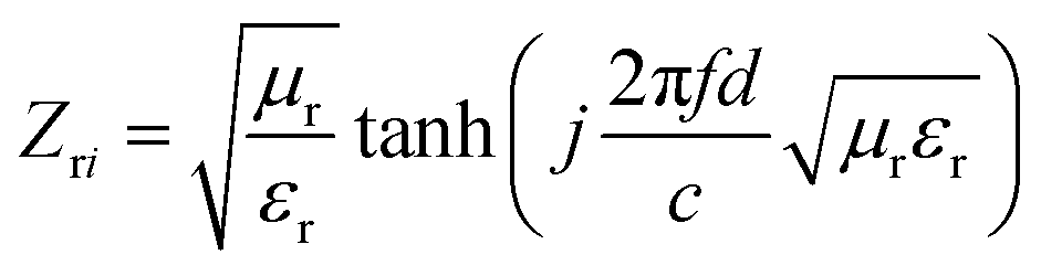
In which the input impedance of the MA layer, Zri, is given by:
 | (11) |
As a result, the MA properties of the gradient multilayer composites containing n layers of materials with different graphene content can be calculated by eqn (6)–(11).
3.2 MA properties of single-layer graphene/TPU composite foams
Single-layer graphene/TPU composite foams with very similar foam ratio but different graphene contents were prepared through the TIPS method. Fig. 2a–g gives the cell morphology of single-layer graphene/TPU composite foams. As seen, samples S-1, S-2, S-3 and S-4 show a uniform cell dispersion and smooth cell walls. With the increasing content of graphene, the cell walls become rough as observed in the SEM image of Fig. 2e–g. Moreover, the well-defined closed cells gradually change from spherical to polygonal shape with the increment of graphene content. The deformation of the cell wall may result from the physical barrier action of graphene on the cell growth.71 Additionally, Fig. 2h–n reveals that the mean pore sizes aggrandize with the increment of graphene content, especially true when the graphene content is greater than 3.8 vol%.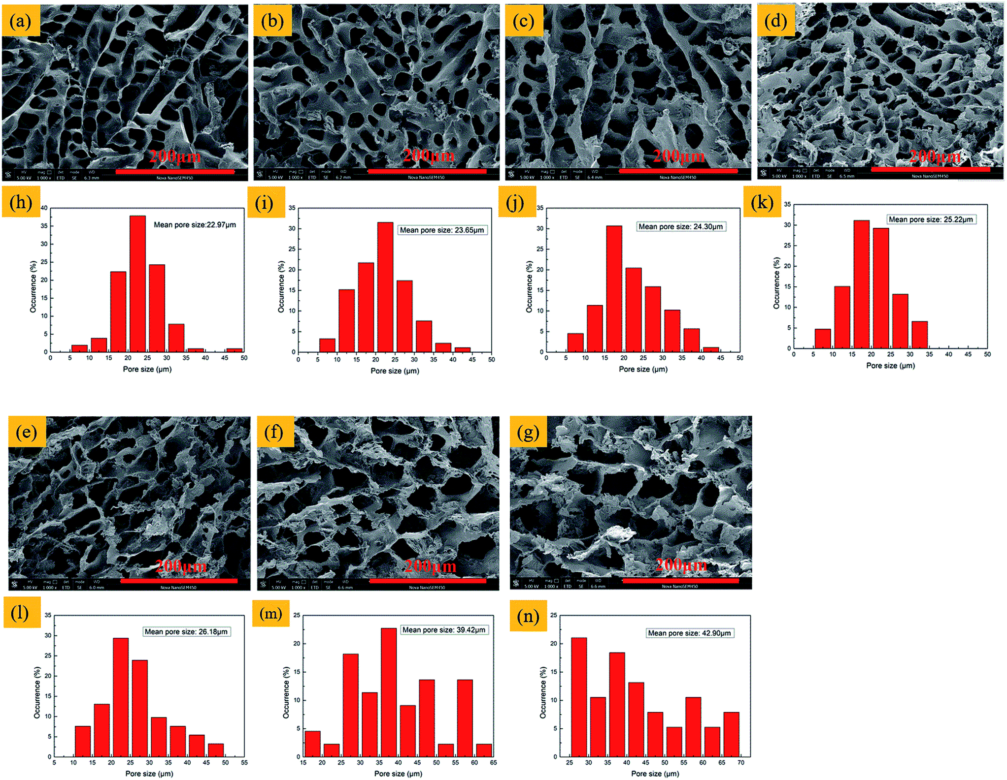 | ||
| Fig. 2 SEM images (a–g) and pore size distribution (h–n) of single-layer graphene/TPU composite foams with different graphene content. (a and h) S-1; (b and i) S-2; (c and j) S-3; (d and k) S-4; (e and l) S-5; (f and m) S-6; (g and n) S-7. | ||
Fig. 3 shows SEM images of the brittle fracture cross-section of sample S-3 etched by DMF. As can be seen from this figure, after the polymeric matrix TPU was etched by DMF, the graphene sheets were exposed on the cell wall. Compared with Fig. 2c, it can be seen that the graphene sheet was completely coated in the TPU matrix. Based on this complete coating structure, good electrical conductivity was obtained and good mechanical properties were provided for graphene/TPU composite foams. Moreover, the selective distribution of graphene on the cell wall resulted in the formation of a three-dimensional conductive network structure.
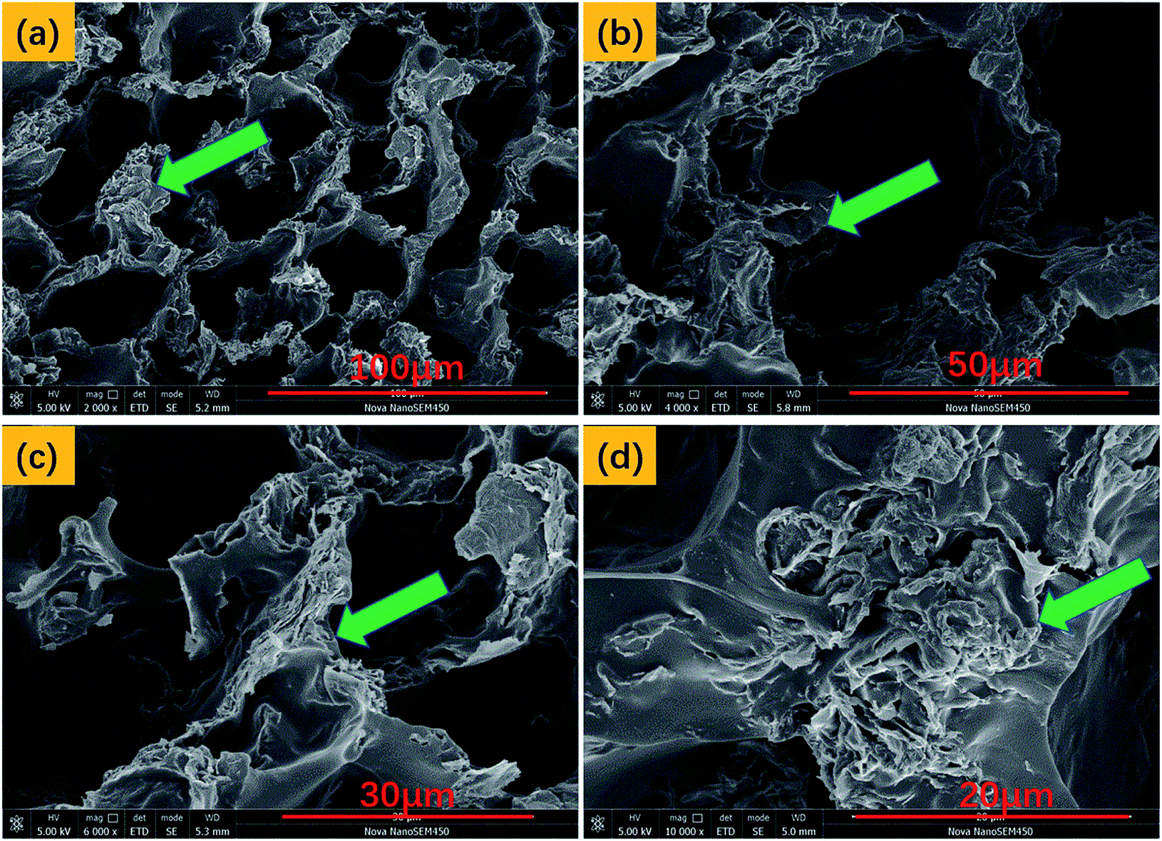 | ||
| Fig. 3 SEM images of sample S-3 etched by DMF. | ||
As is well known, the permittivity, εr, is described as εr = ε′ − jε′′. The polarization effect, expressed by the relative permittivity real part (ε′), is induced by the interaction with bound charges (displacement current).72,73 The effect arising from free electrons (conduction current) results in the dissipation of EM energy, which relates to the imaginary permittivity (ε′′).43 tanδ is represented as ε′′/ε′, revealing the overall EM dielectric losses inside the MAMs.73 These parameters are used to indicate how the absorber dissipates EM energy and converts it into heat.
Fig. 4a–c show frequency dependence of ε′, ε′′ and tanδ of single-layer samples S-1, S-2, S-3, S-4, S-5, S-6 and S-7 with frequency. As is shown in Fig. 4a, with the exception of sample S-3 and S-7, the ε′ values of other single-layer samples aggrandize with the incremental concentration of graphene on account of the monotonically increasing conductivity. The graphene content of sample S-3 is lower than sample S-4, but the ε′ is higher than it. This abnormal phenomenon may be caused by the formation of three-dimensional conductive network structure with good cell structure, shown in Fig. 3a and 6b. As for S-7, the lower ε′ may result from a graphene content exceeding the percolation threshold, thus leading to a decrease in conductivity.74–79 As demonstrated in Fig. 4b, we can observe that both the ε′′ values of S-6 and S-7 are larger than those of other samples in the range of 7.5–18 GHz due to the free electron effect caused by high graphene content is more strongly dissipative to EM energy at higher frequency bands.43,80
 | ||
| Fig. 4 Real parts (ε′), imaginary parts (ε′′) of the complex permittivity (a and b) and tanδ (c) of single-layer graphene/TPU composite foams with different graphene content in the frequency range of 2–18 GHz. | ||
It is known that the tanδ is the quotient of the real and imaginary parts of relative permittivity, which is given by the following equation:
 | (12) |
According to eqn (12), a higher tanδ is determined by lower ε′ and higher ε′′, sample S-7 just satisfies both of them. As is illustrated in Fig. 4c, the dielectric loss value of sample S-7 is much higher than the other six samples in the wide frequency range of 10.3–18 GHz, indicating that sample S-7 possesses a strong ability to dissipate EM energy.
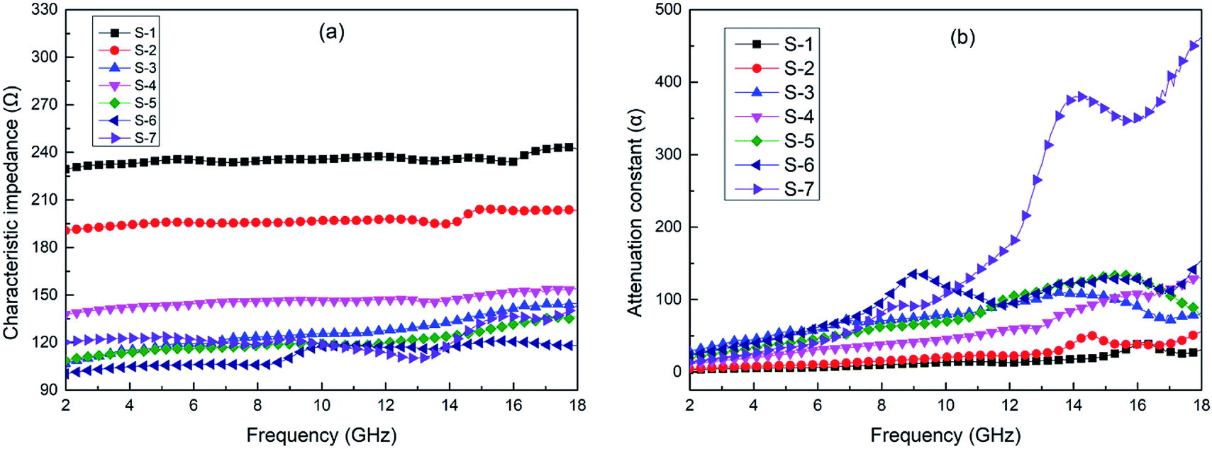
The characteristic impedance ηr and attenuation constant α of the single-layer graphene/TPU composite foams with different graphene content are calculated by the eqn (1) and (2) and demonstrated in Fig. 5a and b. As shown in the figures, the average characteristic impedance of S-1 and S-2, 236 Ω and 197 Ω, respectively, are close to the free space (377 Ω), which is favorable for them to be used as impedance matching layer to reduce the reflection of incident microwaves on the surface of the absorber. However, the attenuation constant of S-1 and S-2 are relatively low among all the single-layer samples, impeding effective absorption of microwaves. Fortunately, the attenuation constant α of S-7 is much larger than the other six single-layer samples in the range of 10.3–18 GHz, as illustrated in Fig. 5b, rendering the incident EM energy to be greatly dissipated. Nevertheless, its lower average characteristic impedance (123 Ω) will cause the swingeing reflection of the incident microwave on its surface, which will prevent it from being used as an efficient MAM. As for the other samples, they all possess lower characteristic impedance and attenuation constant, both of which are unfavorable factors for their use as single-layer MAMs.
 | ||
| Fig. 5 The characteristic impedance (a) and attenuation constant (b) of single-layer foamed graphene/TPU composites with different foam ratio in the frequency range of 2–18 GHz. | ||
Fig. 6a shows the electrical conductivity of single-layer graphene/TPU composite foams with different graphene content. When the graphene concentration increased from 1.3 vol% to 4.6 vol%, the conductivity increased with the filler content. The graphene, selectively dispersed over the cellular walls by foaming, formed a three-dimensional conductive network structure, as shown in the Fig. 6b, causing a significant enhancement in the electrical conductivity with increasing graphene content. With regard to sample S-1, with a very low electrical conductivity of 2.6 × 10⁻¹¹ S cm−1, signifying it is an admirable wave-transmitting material on account of good impedance matching. Sample S-6 exhibited a relatively high electrical conductivity of 1.5 × 10⁻³ S cm−1, indicating that S-6 is an electric conductor. Therefore, the incident microwave propagating into sample S-6 can be effectively absorbed. However, when the graphene content further increased to 5 vol%, the trend of raised conductivity was interrupted. This phenomenon originates from the fact that excessive addition of graphene leads to the occurrence of agglomeration. This agglomeration destroys partial three-dimensional conductive network structure that has been established well, resulting in the occurrence of reduced conductivity.79
 | ||
| Fig. 6 (a) The electrical conductivity of single-layer graphene/TPU composite foams with different graphene content. (b) The three-dimensional conductive network structure. | ||
According to the transmission-line theory, RL of single-layer samples S-1, S-2, S-3, S-4, S-5, S-6 and S-7 could be calculated by eqn (10) and (11). As a result, Fig. 7a–g show frequency dependence of reflection loss of all the single-layer samples when the thickness increases from 2.5 to 5 mm. It turns out that the minimum reflection loss values of S-1 and S-2 were both higher than −10 dB, manifesting that these two single-layer samples did not generate meaningful MA effect at the thickness of 2.5–5 mm on account of their lower attenuation constant. As for samples S-4 and S-5, their minimum reflection loss values are less than −20 dB (99% EM energy absorption), and their maximum EB values are only 2.5 GHz and 2.7 GHz respectively, these performance indexes are still difficult to satisfy their use as broadband effective MAMs. With regard to samples S-3, S-6 and S-7, due to the effective absorption of the incident microwave induced by the dielectric relaxation/resonance and electrical conduction of graphene when the microwaves enter into the composite foams,43 the RLmin can reach −36.5 dB, −39.0 dB and −39.7 dB, respectively. However, narrow effective absorption bandwidth, 3.6 GHz, 1.7 GHz and 2.5 GHz, respectively, limits their use to confined band ranges.
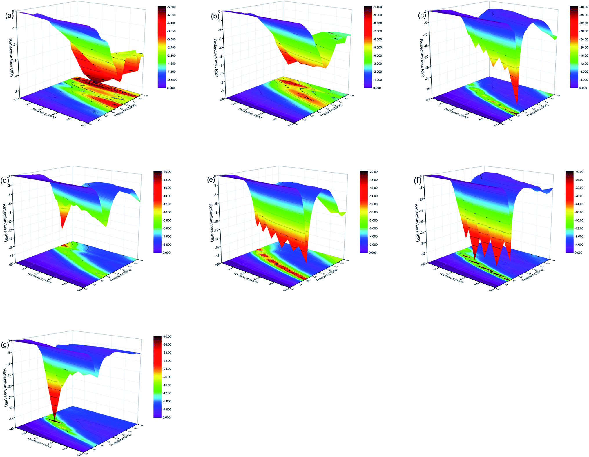 | ||
| Fig. 7 Three-dimensional reflection loss plots of single-layer graphene/TPU composite foams with different graphene content when the thickness increases from 2.5 to 5 mm. (a) S-1; (b) S-2; (c) S-3; (d) S-4; (e) S-5; (f) S-6; (g) S-7. | ||
According to the above analysis of permittivity, dielectric loss, characteristic impedance, attenuation constant and conductivity, the relationship between the microwave absorption and these characteristic parameter of single-layer graphene/TPU composite foams became more pronounced. The single-layer sample with lower the conductivity, such as sample S-1 and S-2, possessed a lower real part of the permittivity, so that the characteristic impedance was closer to the air, which was beneficial to reduce the reflection of the incident microwave on the surface of single-layer absorber, aggrandizing the incident amount. However, the single-layer sample with lower conductivity had a lower dielectric loss and attenuation constant, which greatly obstructed the effective attenuation of microwaves inside the single-layer absorber. For graphene/TPU composite foams with higher conductivity, such as sample S-6 and S-7, although they equipped high dielectric constant and dielectric loss, their lower characteristic impedance greatly impeded that the incident microwave propagated into the monolayer absorber. Without doubt, these single-layer samples with a large attenuation constant played a key role in dissipating energy of microwaves that had entered into the interior of them.
In summary, single-layer graphene/TPU composite foams are difficult to be used as broadband efficient MAMs. To attain satisfactory MA properties, single-layer graphene/TPU composite foams with different graphene content were selected as component layers to design multilayer MAMs with gradient graphene content to realize good impedance matching and strong attenuation capacity. Samples S-1 and S-2 with lower ε′ were selected as impedance matching layers of multilayered MAMs to reduce the reflection of incident microwaves on the surface of the absorber. Samples S-6 and S-7 with higher ε′ and tanδ were chosen as strong MA layer for constructing multilayered MAMs.
3.3 MA properties of multilayer graphene/TPU composite foams with gradient graphene content
In this part, we designed a multilayer model composed of samples S-1, S-2, S-3, S-4, S-5, S-6 and S-7, the schematic of which is shown in Fig. 1. The layer number for the research models, 2, 3, 4 or 5, denoted as two layer (2L), three layer (3L), four layer (4L) and five layer (5L), respectively. According to the analysis results of complex permittivity, dielectric loss, characteristic impedance and attenuation constant of the single-layer samples, sample S-1 with the highest characteristic impedance and S-7 with the highest attenuation constant were selected as the impedance matching layer and strong MA layer of sample 2L, respectively. In the same way, samples S-1, S-4 and S-7 were selected as the constituent layer of sample 3L. Samples S-1, S-2, S-6 and S-7 were used to construct sample 4L and samples S-1, S-3, S-4, S-6 and S-7 were the basic composition unit of sample 5L. Cross-sectional morphology of 2L, 3L, 4L and 5L graphene/TPU composite foams with gradient graphene content is shown in Fig. 8. As shown in the Fig. 8a–d, layer interface can be clearly observed and the cell size of multilayer samples becomes larger from topside to bottom side with the increasing graphene content. The thickness of each layer of multilayer samples is also almost the same, which averts the issue that the input impedance is not uniformly changed by the uneven thickness of the layer. | ||
| Fig. 8 Cross-sectional morphology of 2L, 3L, 4L and 5L graphene/TPU composite foams with gradient graphene content. (a) 2L; (b) 3L; (c) 4L; (d) 5L. | ||
The RL of graphene/TPU composite foams with different layer number could be calculated by eqn (6)–(11). Fig. 9 shows the relationship of RL and the frequency of the gradient multilayer samples with different layer number. It can be seen directly from the figure that the lowest RLmin of samples 2L, 3L, 4L and 5L can be obtained at the thickness of 5 mm, 3.5 mm, 3 mm and 2.5 mm respectively, among which the RLmin of 2L, 3L, 4L and 5L can attain −36.7 dB, −39.5 dB, −34.2 dB and −43.7 dB respectively at their corresponding thickness, shown in Table 2. Further, we found that the widest EB of 9.9 GHz, 6.7 GHz, 5.2 GHz and 4.4 GHz can be obtained at the thickness of 5 mm, 3.5 mm, 3 mm and 2.5 mm, respectively. Moreover, EB value decreases as the enhancive layer number, which may be due to the characteristic impedance of multilayer samples decreases with the incremental layer number. In addition, with the increment of number of layers, the matching thickness of the optimal MA performance of multilayer samples decreases, indicating that gradient multilayer design of graphene content can effectively reduce the thickness of MAMs.
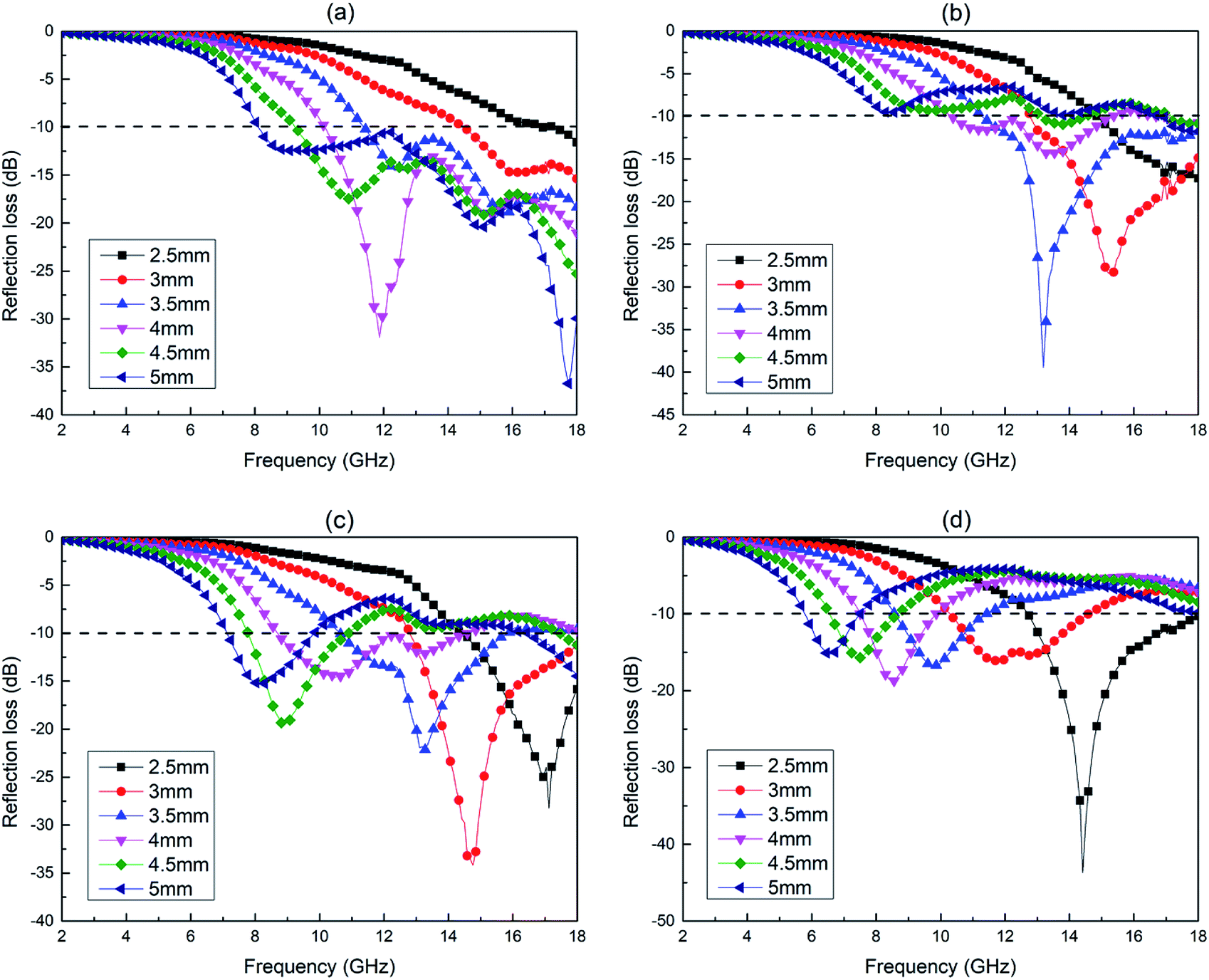 | ||
| Fig. 9 Reflection loss plots of multilayer graphene/TPU composite foams with gradient graphene content when the thickness increases from 2.5 to 5 mm. (a) 2L (S-1 and S-7); (b) 3L (S-1, S-4 and S-7); (c) 4L (S-1, S-2, S-6 and S-7); (d) 5L (S-1, S-3, S-4, S-6 and S-7). | ||
| Sample | Graphene content (vol%) | EB (GHz) | RLmin (dB) |
|---|---|---|---|
| 2L (5 mm) | 3.3 | 9.9 | −36.7 |
| C-2L (5 mm) | 3.3 | 0.1 | −10.5 |
| 3L (3.5 mm) | 3.3 | 6.7 | −39.5 |
| C-3L (3.5 mm) | 3.3 | 0 | −7.5 |
| 4L (3 mm) | 3.3 | 5.2 | −34.2 |
| C-4L (3 mm) | 3.3 | 0 | −8.5 |
| 5L (2.5 mm) | 3.4 | 5.3 | −43.7 |
| C-5L (2.5 mm) | 3.4 | 2.5 | −15.7 |
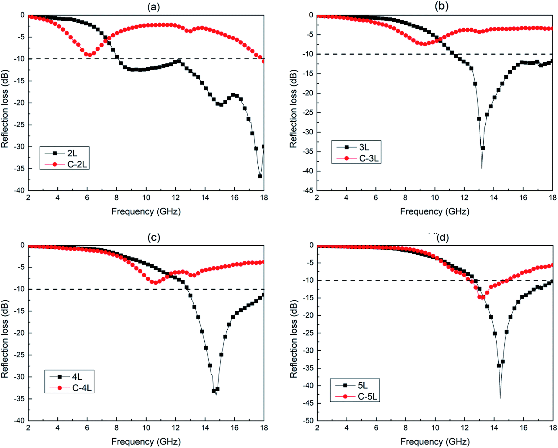
The 2L, 3L, 4L and 5L graphene/TPU composite foams were compared with single-layer samples (C-2L, C-3L, C-4L and C-5L) consistent with the average graphene content of corresponding multilayer samples, their MA properties were shown in Fig. 10 and Table 2, respectively. As can be seen from Fig. 10 and Table 2, RLmin of all the multilayer samples are lower than the corresponding single-layer samples. Moreover, all the multilayer samples produced broadband microwave absorption while their corresponding single-layer samples generate very narrow or even no effective absorption bandwidth. All the above comparison results have proved that gradient multilayer structure design with graphene content is an effective method to enhance the MA performance of graphene/TPU composite foams.
 | ||
| Fig. 10 RL spectra of multilayer graphene/TPU composite foams with gradient graphene content and single-layer samples consistent with the average graphene content of corresponding multilayer samples. (a) 2L (S-1 and S-7) and C-2L, 5 mm; (b) 3L (S-1, S-4 and S-7) and C-3L, 3.5 mm; (c) 4L (S-1, S-2, S-6 and S-7) and C-4L, 3 mm; (d) 5L (S-1, S-3, S-4, S-6 and S-7) and C-5L, 2.5 mm. | ||
Specifically, 2L graphene/TPU composite foams possess RLmin of −36.7 dB, which is much lower than that of its corresponding single-layer sample C-2L (−10.5 dB) at the thickness of 5 mm, and the EB value of sample 2L (9.9 GHz) is much wider than that of C-2L (0.1 GHz). The RLmin of 3L (−39.5 dB) is also far below its corresponding single-layer sample C-3L (−7.5 dB) at the thickness of 3.5 mm, and the EB value of sample 3L (6.7 GHz) is much larger than that of C-3L (0 GHz, no effective microwave absorption). As for sample 4L, the RLmin of it (−34.2 dB) is likewise much lower than that of sample C-4L (−8.5 dB) at the thickness of 3 mm. In the same way, sample C-4L also do not generate any effective absorption bandwidth (0 GHz). As regards as sample 5L, it has a RLmin of −43.7 dB at the thickness of 2.5 mm, and more importantly, the wider EB value of 5.3 GHz is also possessed by it. The two excellent performance indexes of sample 5L are also superior to the corresponding monolayer sample C-5L. In summary, among all the multilayer samples, sample 2L exhibits the widest EB value and the lower RLmin while sample 5L shows the lowest RLmin and wider EB values at the minimum thickness (2.5 mm). The MA properties of multilayer samples are better than those of corresponding single-layer samples with the same graphene content. What's more, effective regulation of EB value and RLmin can be realized by adjusting the thickness and number of layers or altering the combinatorial mode of single-layer samples with different graphene contents.
The 2L, 3L, 4L and 5L graphene/TPU composite foams with gradient graphene content were compared with other materials in the past literatures, and the results were shown in Table 3. It is clear that the EB value of all the multilayer samples were almost entirely wider than these materials in the past literatures. Moreover, the RLmin of sample 5L with the thickness of only 2.5 mm was also much lower than those reported in the literature. More importantly, the EB value and RLmin can be facilely regulated by optimizing the number of layers and thickness, greatly facilitating their use as MAMs.
| Sample | EB (GHz) | RLmin (dB) |
|---|---|---|
| 2L | 9.9 | −36.7 |
| 3L | 6.7 | −39.5 |
| 4L | 5.2 | −34.2 |
| 5L | 5.3 | −43.7 |
| Literature 5 (ref. 81) | 3.3 | −43.60 |
| Literature 2 (ref. 82) | 3.4 | −31.88 |
| Literature 3 (ref. 83) | 0.9 | −22.05 |
| Literature 4 (ref. 84) | 3.3 | −33.20 |
| Literature 8 (ref. 85) | 4.0 | −31.00 |
| Literature 1 (ref. 86) | 4.2 | −27.80 |
| Literature 6 (ref. 87) | 4.6 | −34.20 |
| Literature 7 (ref. 88) | 5.3 | −29.05 |
Fig. 11 is a figure showing the microwave absorption mechanism of multilayer graphene/TPU composite foams with gradient graphene content and their corresponding monolayer samples at the same thickness. As is shown in Fig. 11a and b, as the average contents of graphene in the two samples are identical, the incident microwave that goes into the material can be absorbed by graphene and the absorbing effect can be enhanced with the gradient multilayer structural design. The mechanism of the gradient multilayer structure to effectively enhance the absorption performance based on the following factors: first, S-1 is used as impedance matching layer to construct gradient multilayer MAMs, reducing the reflection of microwaves on the surface of the MAMs and increasing the proportion of incident microwaves entering into the interior of MAMs in favour of enhancing the dissipation of EM energy inside the absorber. Second, multilayer structure facilitates the multiple reflection of microwaves at the layer interface, which promotes the interference cancellation of microwaves. Moreover, as is shown in Fig. 11a, this multiple reflection prolongs the transmission path of microwaves inside the absorber, extending its consumption time compared with monolayer samples.
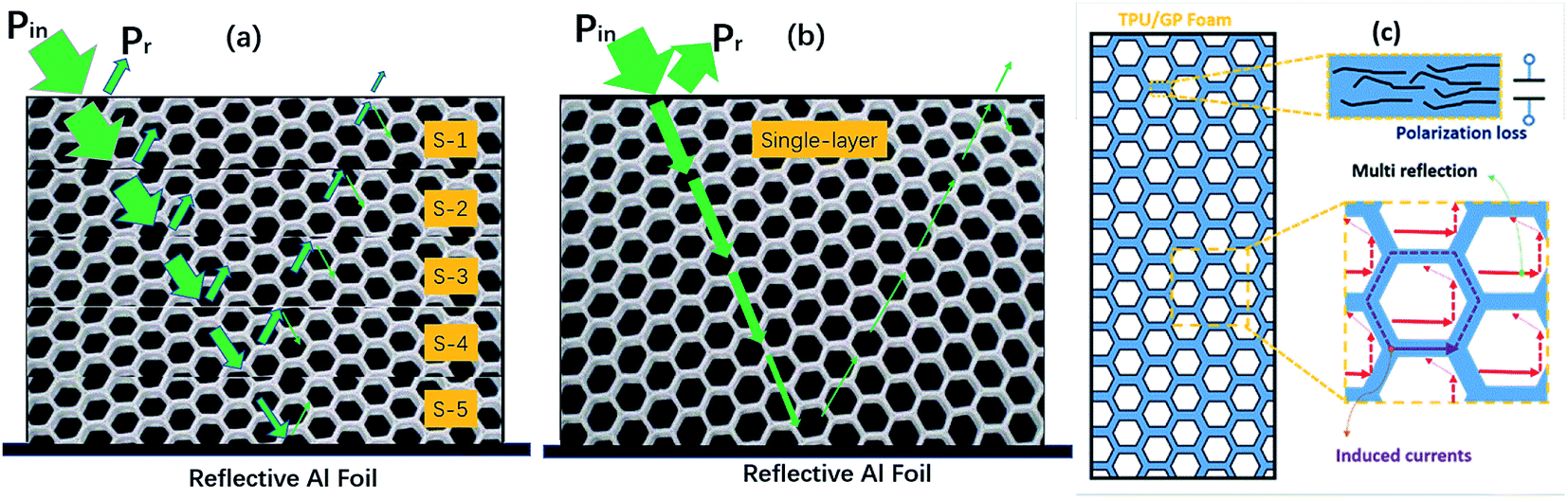 | ||
| Fig. 11 Microwave absorption mechanism diagram. (a and b) MA mechanism diagram of multilayer graphene/TPU composite foams with gradient graphene content and their corresponding single-layer sample at the same thickness. (c) MA mechanism of porous structure. | ||
On the other hand, as can be seen from Fig. 11c, porous structure changes the transmission path of the microwave inside absorbers: when microwave propagates into the interior of the MAMs, it actually passes through not only the cell wall composed of the graphene/TPU composites, but the cells in the absorbers. The skin depth (δ) (depth at which the field drops to 1/e of its original strength) is expressed as
 | (13) |
According to the transmission-line theory, the characteristic impedance (Zi) of the multilayer MAMs were calculated by eqn (6)–(9), and the characteristic impedance (Zri) of the single-layer MAMs can be given by eqn (11). Here normalized impedance, Z = Zri/Z0, was used to evaluate the impedance matching characteristic. If the absorber possess a better impedance matching characteristic, the modulus of Z should be infinitely close to 1.91 Fig. 12 show the |Z| versus frequency curves for 2L, 3L, 4L and 5L graphene/TPU composite foams with gradient graphene content and their corresponding monolayer samples at the same thickness. It could be found that the |Z| values for 2L, C-2L, 3L, C-3L, 4L, C-4L, 5L and C-5L are in a range of 0.01–2.09, 0.02–2.15, 0.01–2.00, 0.01–2.67, 0.01–1.55, 0.01–2.45, 0.01–1.32 and 0.01–2.35, respectively.
 | ||
| Fig. 12 The |Z| versus frequency curves for 2L, 3L, 4L, 5L graphene/TPU composite foams and their corresponding monolayer samples (C-2L, C-3L, C-4L and C-5L) at the same thickness. | ||
It can be clearly observed that all the |Z| of multilayer samples are closer to 1 compared with their corresponding monolayer samples. Therefore, the enhanced MA property of the multilayer absorber is attributed to their better impedance matching characteristic. For sample 2L, its |Z| in the higher frequency band is closer to 1 than C-2L, which also confirms the broadband absorption it produces at high frequencies. Similarly, the excellent MA performance of sample 3L at higher frequency band is ascribed to the fact that its |Z| value is closer to 1 than sample C-3L. Samples 4L and 5L exhibited similar trends for the identical reasons.
4. Conclusion
Monolayer graphene/TPU composite foams with different amounts of graphene and multilayer graphene/TPU composite foams with gradient graphene content were manufactured in this work. The balance between characteristic impedance and attenuation constant were successfully adjusted by controlling the absorbent content gradient distribution in the multilayered structure and selectively distributing absorbents on the cell walls. Moreover, effective regulation of EB value and RLmin have been realized by adjusting the thickness and layer number or altering the combinatorial mode of single-layer samples with different graphene contents to endow these multilayered composite foams with the optimal MA property. In addition, the mechanism of microwave dissipation by gradient multilayer and porous structures has been elucidated. The EB values of multilayer samples were all wider than those of their corresponding monolayer samples with the same graphene content and multilayer samples equipped much lower RLmin than single-layer samples. Among all the multilayer samples, 2L graphene/TPU composite foams with a thickness of 5 mm exhibits the widest EB value of 9.9 GHz and the lower RLmin (−36.7 dB) while 5L graphene/TPU composite foams with a thickness of only 2.5 mm shows the lowest RLmin of −43.7 dB and wider EB values (5.3 GHz).Conflicts of interest
There are no conflicts to declare.Acknowledgements
The authors are grateful to the National Natural Science Foundation of China (51473103 and 51873112) for financial support of this work.References
- B. Shen, W. Zhai and W. Zheng, Adv. Funct. Mater., 2014, 24, 4542–4548 CrossRef CAS.
- D.-X. Yan, H. Pang, B. Li, R. Vajtai, L. Xu, P.-G. Ren, J.-H. Wang and Z.-M. Li, Adv. Funct. Mater., 2015, 25, 559–566 CrossRef CAS.
- B. Shen, Y. Li, D. Yi, W. Zhai, X. Wei and W. Zheng, Carbon, 2016, 102, 154–160 CrossRef CAS.
- Y. Wang, D. Chen, X. Yin, P. Xu, F. Wu and M. He, ACS Appl. Mater. Interfaces, 2015, 7, 26226–26234 CrossRef CAS.
- H.-B. Zhao, Z.-B. Fu, H.-B. Chen, M.-L. Zhong and C.-Y. Wang, ACS Appl. Mater. Interfaces, 2016, 8, 1468–1477 CrossRef CAS.
- M. Han, X. Yin, Z. Hou, C. Song, X. Li, L. Zhang and L. Cheng, ACS Appl. Mater. Interfaces, 2017, 9, 11803–11810 CrossRef CAS.
- M. Han, X. Yin, X. Li, B. Anasori, L. Zhang, L. Cheng and Y. Gogotsi, ACS Appl. Mater. Interfaces, 2017, 9, 20038–20045 CrossRef CAS.
- Z. Zhang, X. Lv, Y. Chen, P. Zhang, M. Sui, H. Liu and X. Sun, Nanomaterials, 2019, 9, 292 CrossRef CAS.
- R. C. Che, L. M. Peng, X. F. Duan, Q. Chen and X. L. Liang, Adv. Mater., 2004, 16, 401–405 CrossRef CAS.
- H. Sun, R. Che, X. You, Y. Jiang, Z. Yang, J. Deng, L. Qiu and H. Peng, Adv. Mater., 2014, 26, 8120–8125 CrossRef CAS.
- M.-M. Lu, M.-S. Cao, Y.-H. Chen, W.-Q. Cao, J. Liu, H.-L. Shi, D.-Q. Zhang, W.-Z. Wang and J. Yuan, ACS Appl. Mater. Interfaces, 2015, 7, 19408–19415 CrossRef CAS.
- N. Li, G.-W. Huang, Y.-Q. Li, H.-M. Xiao, Q.-P. Feng, N. Hu and S.-Y. Fu, ACS Appl. Mater. Interfaces, 2017, 9, 2973–2983 CrossRef CAS.
- L. Yan, C. Hong, B. Sun, G. Zhao, Y. Cheng, S. Dong, D. Zhang and X. Zhang, ACS Appl. Mater. Interfaces, 2017, 9, 6320–6331 CrossRef CAS.
- Y. Huang, X. Yuan, M. Chen, W.-L. Song, J. Chen, Q. Fan, L. Tang and D. Fang, ACS Appl. Mater. Interfaces, 2018, 10, 44731–44740 CrossRef CAS.
- X.-X. Wang, T. Ma, J.-C. Shu and M.-S. Cao, Chem. Eng. J., 2018, 332, 321–330 CrossRef CAS.
- Z. Li, A. Haigh, C. Soutis and A. Gibson, Compos. Struct., 2019, 208, 224–232 CrossRef.
- Y.-L. Ren, H.-Y. Wu, M.-M. Lu, Y.-J. Chen, C.-L. Zhu, P. Gao, M.-S. Cao, C.-Y. Li and Q.-Y. Ouyang, ACS Appl. Mater. Interfaces, 2012, 4, 6436–6442 CrossRef CAS.
- X.-J. Zhang, G.-S. Wang, W.-Q. Cao, Y.-Z. Wei, J.-F. Liang, L. Guo and M.-S. Cao, ACS Appl. Mater. Interfaces, 2014, 6, 7471–7478 CrossRef CAS.
- Y. Zhang, Y. Huang, T. Zhang, H. Chang, P. Xiao, H. Chen, Z. Huang and Y. Chen, Adv. Mater., 2015, 27, 2049–2053 CrossRef CAS.
- B. Qu, C. Zhu, C. Li, X. Zhang and Y. Chen, ACS Appl. Mater. Interfaces, 2016, 8, 3730–3735 CrossRef CAS.
- F. Sharif, M. Arjmand, A. A. Moud, U. Sundararaj and E. P. L. Roberts, ACS Appl. Mater. Interfaces, 2017, 9, 14171–14179 CrossRef CAS.
- Y. Wu, Z. Wang, X. Liu, X. Shen, Q. Zheng, Q. Xue and J.-K. Kim, ACS Appl. Mater. Interfaces, 2017, 9, 9059–9069 CrossRef CAS.
- D. X. Yan, H. Pang, B. Li, R. Vajtai, L. Xu, P. G. Ren, J. H. Wang and Z. M. Li, Adv. Funct. Mater., 2015, 25, 559–566 CrossRef CAS.
- T.-W. Lee, S.-E. Lee and Y. G. Jeong, Compos. Sci. Technol., 2016, 131, 77–87 CrossRef CAS.
- Y. Li, B. Shen, D. Yi, L. Zhang, W. Zhai, X. Wei and W. Zheng, Compos. Sci. Technol., 2017, 138, 209–216 CrossRef CAS.
- Y. Yang, M. C. Gupta, K. L. Dudley and R. W. Lawrence, Nano Lett., 2005, 5, 2131–2134 CrossRef CAS.
- Y. Yang, M. C. Gupta, K. L. Dudley and R. W. Lawrence, Adv. Mater., 2005, 17, 1999–2003 CrossRef CAS.
- A. Fletcher, M. C. Gupta, K. L. Dudley and E. Vedeler, Compos. Sci. Technol., 2010, 70, 953–958 CrossRef CAS.
- V. Eswaraiah, V. Sankaranarayanan and S. Ramaprabhu, Macromol. Mater. Eng., 2011, 296, 894–898 CrossRef CAS.
- H.-B. Zhang, Q. Yan, W.-G. Zheng, Z. He and Z.-Z. Yu, ACS Appl. Mater. Interfaces, 2011, 3, 918–924 CrossRef CAS.
- D.-X. Yan, P.-G. Ren, H. Pang, Q. Fu, M.-B. Yang and Z.-M. Li, J. Mater. Chem., 2012, 22, 18772–18774 RSC.
- Y. Chen, Y. Li, D. Xu and W. Zhai, RSC Adv., 2015, 5, 82034–82041 RSC.
- Y. Gao, C. Wang, J. Li and S. Guo, Composites, Part A, 2019, 117, 65–75 CrossRef CAS.
- H. Lv, X. Liang, Y. Cheng, H. Zhang, D. Tang, B. Zhang, G. Ji and Y. Du, ACS Appl. Mater. Interfaces, 2015, 7, 4744–4750 CrossRef CAS.
- H. Lv, X. Liang, G. Ji, H. Zhang and Y. Du, ACS Appl. Mater. Interfaces, 2015, 7, 9776–9783 CrossRef CAS.
- C. Tian, Y. Du, P. Xu, R. Qiang, Y. Wang, D. Ding, J. Xue, J. Ma, H. Zhao and X. Han, ACS Appl. Mater. Interfaces, 2015, 7, 20090–20099 CrossRef CAS.
- A. Oikonomou, T. Giannakopoulou and G. Litsardakis, J. Magn. Magn. Mater., 2007, 316, e827–e830 CrossRef CAS.
- G. Shen, M. Xu and Z. Xu, Mater. Chem. Phys., 2007, 105, 268–272 CrossRef CAS.
- Y. Zhou, X.-L. Shi, J. Yuan, X.-Y. Fang and M.-S. Cao, Chin. Phys. Lett., 2007, 24, 3264 CrossRef CAS.
- H. Yanfei and G. Rongzhou, EPL, 2009, 85, 58003 CrossRef.
- Y. Wang, Int. J. Mater. Res., 2013, 105, 3–12 CrossRef.
- Y. Qing, W. Zhou, S. Huang, Z. Huang, F. Luo and D. Zhu, J. Alloys Compd., 2014, 583, 471–475 CrossRef CAS.
- X. Gao, J. Li, Y. Gao, S. Guo, H. Wu and R. Chen, Compos. Sci. Technol., 2016, 130, 10–19 CrossRef CAS.
- Y. Liu, X. Zhao and X. Tuo, J. Text. Inst., 2016, 107, 483–492 CrossRef CAS.
- X. Wang, H. Yan, R. Xue and S. Qi, J. Mater. Sci.: Mater. Electron., 2017, 28, 519–525 CrossRef CAS.
- S.-E. Lee, J.-H. Kang and C.-G. Kim, Compos. Struct., 2006, 76, 397–405 CrossRef.
- M. Chen, Y. Zhu, Y. Pan, H. Kou, H. Xu and J. Guo, Mater. Des., 2011, 32, 3013–3016 CrossRef CAS.
- L. Monnereau, L. Urbanczyk, J.-M. Thomassin, T. Pardoen, C. Bailly, I. Huynen, C. Jérôme and C. Detrembleur, Polymer, 2015, 59, 117–123 CrossRef CAS.
- J.-M. Thomassin, C. Jerome, T. Pardoen, C. Bailly, I. Huynen and C. Detrembleur, Mater. Sci. Eng., R, 2013, 74, 211–232 CrossRef.
- A. Shah, A. Ding, Y. Wang, L. Zhang, D. Wang, J. Muhammad, H. Huang, Y. Duan, X. Dong and Z. Zhang, Carbon, 2016, 96, 987–997 CrossRef CAS.
- S. C. Dang, Y. Lin, X. Z. Wei and H. Ye, J. Mater. Sci.: Mater. Electron., 2018, 29, 17651–17660 CrossRef CAS.
- B. Zhao, B. Fan, G. Shao, W. Zhao and R. Zhang, ACS Appl. Mater. Interfaces, 2015, 7, 18815–18823 CrossRef CAS.
- P. Liu, Z. Yao, J. Zhou, Z. Yang and L. B. Kong, J. Mater. Chem. C, 2016, 4, 9738–9749 RSC.
- Z. Li, X. Li, Y. Zong, G. Tan, Y. Sun, Y. Lan, M. He, Z. Ren and X. Zheng, Carbon, 2017, 115, 493–502 CrossRef CAS.
- H. Xu, X. Yin, M. Zhu, M. Han, Z. Hou, X. Li, L. Zhang and L. Cheng, ACS Appl. Mater. Interfaces, 2017, 9, 6332–6341 CrossRef CAS.
- X. Sun, J. He, G. Li, J. Tang, T. Wang, Y. Guo and H. Xue, J. Mater. Chem. C, 2013, 1, 765–777 RSC.
- B. Zhao, G. Shao, B. Fan, W. Zhao and R. Zhang, Phys. Chem. Chem. Phys., 2015, 17, 2531–2539 RSC.
- D. R. Lloyd, K. E. Kinzer and H. S. Tseng, J. Membr. Sci., 1990, 52, 239–261 CrossRef CAS.
- Y. S. Nam and T. G. Park, Biomaterials, 1999, 20, 1783–1790 CrossRef CAS.
- H. Zhang, I. Hussain, M. Brust, M. F. Butler, S. P. Rannard and A. I. Cooper, Nat. Mater., 2005, 4, 787 CrossRef CAS.
- J. Zou, J. Liu, A. S. Karakoti, A. Kumar, D. Joung, Q. Li, S. I. Khondaker, S. Seal and L. Zhai, ACS Nano, 2010, 4, 7293–7302 CrossRef CAS.
- L. Qiu, J. Z. Liu, S. L. Y. Chang, Y. Wu and D. Li, Nat. Commun., 2012, 3, 1241 CrossRef.
- C. Wang, Y. Ding, Y. Yuan, X. He, S. Wu, S. Hu, M. Zou, W. Zhao, L. Yang, A. Cao and Y. Li, J. Mater. Chem. C, 2015, 3, 11893–11901 RSC.
- A. T. E. Vilian, S. An, S. R. Choe, C. H. Kwak, Y. S. Huh, J. Lee and Y.-K. Han, Biosens. Bioelectron., 2016, 86, 122–128 CrossRef CAS.
- H. Liu, M. Dong, W. Huang, J. Gao, K. Dai, J. Guo, G. Zheng, C. Liu, C. Shen and Z. Guo, J. Mater. Chem. C, 2017, 5, 73–83 RSC.
- X. Wei, X. Cao, Y. Wang, G. Zheng, K. Dai, C. Liu and C. Shen, Compos. Sci. Technol., 2017, 149, 166–177 CrossRef CAS.
- Z. Zeng, H. Jin, M. Chen, W. Li, L. Zhou, X. Xue and Z. Zhang, Small, 2017, 13, 1701388 CrossRef.
- E. Rezvanpanah, S. R. G. Anbaran and E. Di Maio, Carbon, 2017, 125, 32–38 CrossRef CAS.
- H. Sehaqui, M. Salajková, Q. Zhou and L. A. Berglund, Soft Matter, 2010, 6, 1824–1832 RSC.
- F. Qin and C. Brosseau, J. Appl. Phys., 2012, 111, 061301 CrossRef.
- J. Ling, W. Zhai, W. Feng, B. Shen, J. Zhang and W. g. Zheng, ACS Appl. Mater. Interfaces, 2013, 5, 2677–2684 CrossRef CAS.
- S.-L. Shi and J. Liang, Nanotechnology, 2008, 19, 255707 CrossRef.
- D. Micheli, C. Apollo, R. Pastore and M. Marchetti, Compos. Sci. Technol., 2010, 70, 400–409 CrossRef CAS.
- K. R. Paton and A. H. Windle, Carbon, 2008, 46, 1935–1941 CrossRef CAS.
- C.-W. Nan, Y. Shen and J. Ma, Annu. Rev. Mater. Res., 2010, 40, 131–151 CrossRef CAS.
- P. Saini, V. Choudhary, B. Singh, R. Mathur and S. Dhawan, Synth. Met., 2011, 161, 1522–1526 CrossRef CAS.
- F. Qin and C. Brosseau, J. Appl. Phys., 2012, 111, 4 Search PubMed.
- P. Xie, H. Li, B. He, F. Dang, J. Lin, R. Fan, C. Hou, H. Liu, J. Zhang and Y. Ma, J. Mater. Chem. C, 2018, 6, 8812–8822 RSC.
- Y. Wang, J. W. Shan and G. J. Weng, J. Appl. Phys., 2015, 118, 065101 CrossRef.
- P. Xu, X. Han, C. Wang, D. Zhou, Z. Lv, A. Wen, X. Wang and B. Zhang, J. Phys. Chem. B, 2008, 112, 10443–10448 CrossRef CAS.
- G. J. Gou, F. B. Meng, H. G. Wang, M. Jiang, W. Wei and Z. W. Zhou, Nano Res., 2019, 12, 1423–1429 CrossRef CAS.
- Y. Li, S. Li, T. Zhang, L. Shi, S. Liu and Y. Zhao, J. Alloys Compd., 2019, 792, 424–431 CrossRef CAS.
- H. Qiu, X. Luo, J. Wang, X. Zhong and S. Qi, J. Electron. Mater., 2019, 48, 4400–4408 CrossRef CAS.
- Y. Zou, J. Wang, B. Zhang, X. G. Su, S. Q. Huo, S. Yang, W. Chen, X. Wang and J. P. Wang, J. Mater. Sci.: Mater. Electron., 2019, 30, 10321–10331 CrossRef CAS.
- Q. Liao, M. He, Y. M. Zhou, S. X. Nie, Y. J. Wang, B. B. Wang, X. M. Yang, X. H. Bu and R. L. Wang, Langmuir, 2018, 34, 15854–15863 CrossRef CAS PubMed.
- C. Song, X. Yin, M. Han, X. Li, Z. Hou, L. Zhang and L. Cheng, Carbon, 2017, 116, 50–58 CrossRef CAS.
- S. S. Wang, Q. Z. Jiao, X. F. Liu, Y. C. Xu, Q. Shi, S. Yue, Y. Zhao, H. B. Liu, C. H. Feng and D. X. Shi, ACS Sustainable Chem. Eng., 2019, 7, 7004–7013 CrossRef CAS.
- S. S. Wang, Y. Zhao, M. M. Gao, H. L. Xue, Y. C. Xu, C. H. Feng, D. X. Shi, K. H. Liu and Q. Z. Jiao, ACS Appl. Mater. Interfaces, 2018, 10, 42865–42874 CrossRef CAS PubMed.
- N. Joseph, C. Janardhanan and M. T. Sebastian, Compos. Sci. Technol., 2014, 101, 139–144 CrossRef CAS.
- S. D. A. S. Ramoa, G. M. O. Barra, C. Merlini, S. Livi, B. G. Soares and A. Pegoretti, Polym. Adv. Technol., 2018, 29, 1377–1384 CrossRef CAS.
- F. Yan, S. Zhang, X. Zhang, C. Y. Li, C. L. Zhu, X. T. Zhang and Y. J. Chen, J. Mater. Chem. C, 2018, 6, 12781–12787 RSC.
| This journal is © The Royal Society of Chemistry 2019 |