 Open Access Article
The mechanical properties, microstructures and mechanism of carbon nanotube-reinforced oil well cement-based nanocomposites†
Shichao Lu a,
Xiaoyan Wang
 ab,
Zhaorui Meng
 a,
Qingchun Deng
 a,
Fangfang Peng
 a,
Chengcheng Yu
 a,
Xu Hu
 a,
Yi Zhao
 a,
Yangchuan Ke
 *a and
Fengzhong Qi
 *b
*b
aNanochemistry Key Laboratory of China National Petroleum Corporation, College of Science, China University of Petroleum, Beijing, 102249, China. E-mail: kyc06@sohu.com
bCNPC Drilling Research Institute, Beijing, 102206, China. E-mail: qfz69dri@sohu.com
First published on 27th August 2019
Abstract
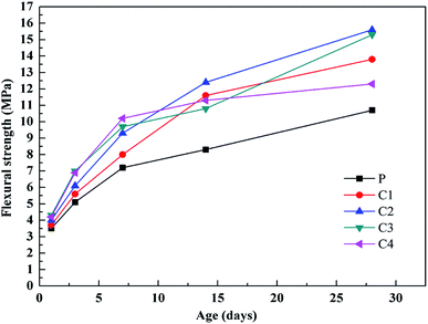
High performance cement-based nanocomposites were successfully fabricated through the use of oil well cement filled with multiwalled carbon nanotubes (MWCNTs) as reinforcements. The dispersibilities of four dispersing agents for the MWCNTs were investigated and compared. The dispersed morphologies and structural characteristics of the MWCNTs were analyzed via TEM, FTIR and Raman spectroscopy studies. The effects of MWCNT addition on the rheological behavior and fluidity of oil well cement slurry were discussed. The mechanical properties of the cement-based nanocomposites with different MWCNT content values and different curing ages were explored and analyzed. Furthermore, the microstructures of the MWCNT reinforced cementitious nanocomposites were characterized via XRD, SEM, EDS, total porosity and pore size distribution studies. The results demonstrated that the 28 day compressive strength and 28 day flexural strength of the 0.05 wt% MWCNT cementitious nanocomposite increased by 37.50% and 45.79%, respectively, compared with a pure cement matrix. The elastic moduli of a 0.05 wt% MWCNT cementitious sample declined by 19.07% and 35.39% under uniaxial and triaxial stress, respectively. XRD and pore structure analysis indicated that the MWCNTs could accelerate the hydration process, increase the amount of hydration products and optimize the pore size distribution within the matrix. Additionally, crack bridging, pulling out, network filling and a calcium-silicate-hydrate (C–S–H) phase were exhibited by SEM images. Meanwhile, the reinforcing and toughening mechanism of MWCNTs was also discussed; these had a beneficial influence on the mechanical properties.
1. Introduction
At present, geological conditions are becoming more complicated1–3 with the continuous exploration and development of tight oil wells and shale gas wells, ultra-deep wells and gas storage wells. The requirements for cementing quality are getting higher and higher. Correspondingly, higher requirements have also been put forward for cementing technology, cementing materials, cement slurry performance and so on.4 Cementing materials are an important aspect of excellent cementing quality, and oil well cement is a main component of cementing materials. However, ordinary cement stone is a brittle material and has inherent defects, such as low tensile strength, poor anti-cracking performance, and low impact strength.5 These defects are likely to cause the destruction of cement rings under an impact load, so that their ability to block underground oil, gas and water layers is weakened, resulting in interlayer channeling and the corrosion of casing pipes.6 These shortcomings not only severely limit the overall performance and durability of oil well cement, but also lead to wells being scrapped in serious circumstances.In order to overcome the aforementioned disadvantages of cementing materials, the concept of introducing additional material at the millimeter/micron scale has been advanced in recent years. Pozzolanic additives (metakaolinite, microsilica, etc.)7,8 and fibers (steel fibers,9–11 glass fibers,12,13 natural fibers14,15 and synthetic fibers16,17) at the millimeter/micron scale are commonly-used materials to reinforce cement matrices. Researchers recognize that each kind of additional reinforcement material possesses its own unique enhancement functionality in terms of strength, ductility, crack-control, and so on. Nevertheless, such reinforcement at the millimeter/micron scale can only limit or delay the expansion of internal micro-cracks in materials, instead of limiting the generation of micro-cracks or restraining nano-cracks.18,19 Cementitious composites, however, exhibit flaws at the nano-scale, where traditional reinforcement is not effective.20
With the development of innovative nanotechnology, dispersing nanomaterials into cement-based composites to develop crack-free concrete with improved mechanical properties and durability is a strategy that has received considerable attention worldwide in recent years. Nanoscale graphene oxide (GO),21 nano-SiO2,22 nano-TiO2,23 nano-MgO,24 nano-Al2O3,25 nano-Fe2O3,26 nano-CaCO3,27 and so on, have opened up new opportunities for the nanosized reinforcement of concrete,28 where a small amount of additive can improve the mechanical performance of a cementitious composite. Compared with other nano-materials, carbon nanotubes (CNTs) are considered one of the most ideal nanomaterials for nano-reinforcement, owing to their excellent mechanical, thermal and electrical properties.29,30 CNTs are hollow tubular channels, which are commonly categorized as either single-walled carbon nanotubes (SWCNTs) or multi-walled carbon nanotubes (MWCNTs) based on the number of concentric tubes.31 MWCNTs can have diameters ranging from 1 nm to 100 nm, while their lengths range from 0.1 to 100 μm.32,33 Their aspect ratios (length-to-diameter ratios) are beyond 1000 in general.33 Meanwhile, the tensile strength of MWCNTs is between 11 GPa and 63 GPa, which is 100 times greater than that of steel.34 Theoretically, the Young's modulus of MWCNTs approaches 1 TPa,35 with an ultimate strain of up to 15%.30 Different from microfiber reinforcements in cement matrices, which contribute to delays in the development of microcracks, MWCNTs, which are distributed on a much finer scale, prevent crack growth at the nanoscale and limit the initiation of micro-cracks.36
In the last few years, many investigations34,37–39 have focused on adding MWCNTs into cement-based composites for the purpose of strength improvement and microstructure reinforcement. Kumar et al.40 explored the effects of MWCNTs on the strength characteristics of hydrated Portland cement paste. Konsta-Gdoutos et al.20 found that the incorporation of MWCNTs obviously affected the nano-micron mechanical properties of a cement matrix. Kowald41 added 0.50 wt% MWCNTs into cement paste and measured a 12% increase in compressive strength. Nochaiya et al.42 researched the microstructural properties of MWCNT/cement nanocomposites. SEM micrographs illustrated good interactions between the MWCNTs and cement hydration products, with the MWCNTs acting as a filler and contributing to the formation of a more compact microstructure and higher strength. A major challenge, however, associated with the incorporation of MWCNTs into cement composites is their poor dispersion. Because of the large surface areas and high surface energy of MWCNTs, van der Waals attraction forces are relatively strong between the MWCNTs, meaning that MWCNTs are prone to agglomeration and the formation of bundle structures.19 Consequently, the reinforcing effects of MWCNTs on cementitious materials are limited, and their interfacial interaction with the cement matrix is weakened.43 Therefore, to achieve favorable reinforcement, the issue of dispersing MWCNTs homogeneously and effectively in the cement matrix is of great importance.44 Currently, technologies designed for effectively dispersing MWCNTs are commonly divided into physical dispersion methods and chemical dispersion methods. Physical modification employs mechanical stress through processes such as ultrasonication,45 ball milling46 and mechanical stirring47 to activate the surfaces of MWCNTs.34 Chemical modification introduces functional groups to the surfaces of MWCNTs through the use of surfactants, polymers or strong inorganic acid treatment. Simone Musso et al.48 compared samples obtained via mixing the same cement paste with three different kinds of MWCNTs (as-grown, annealed and carboxyl-functionalized MWCNTs). Their results demonstrated that the chemical–physical properties of the MWCNTs affected the mechanical behaviors of the cement composites, but flexural and compressive measurements of the composites showed an 80% decrease with the functionalized MWCNTs. Li et al.49 showed that the addition of MWCNTs modified using a mixture of H2SO4/HNO3 into a plain cement matrix moderately enhanced both the compressive and flexural strengths. Cwirzen et al.50 combined polyacrylic acid polymers with sonication treatment to disperse MWCNTs in cement composites. The polyacrylic acid polymers were applied to modify the surfaces of the MWCNTs, to promote bonding between the MWCNTs and cement hydration products. Sáez de Ibarra et al.43 employed arabic gum (a water-soluble surfactant) as a dispersing agent and found improvements in the Young's modulus and compressive strength. Meanwhile, the incorporation of MWCNTs worsened the mechanical properties when no surfactant was used.
Here, in this paper, the effective dispersion of MWCNTs in water was achieved through applying surfactants and, in combination with an ultrasonication and centrifugation process, the dispersions were used to facilitate the preparation of MWCNT-reinforced oil well cement-based nanocomposites. The dispersion performances of the MWCNTs were investigated and four dispersing agents were compared. The dispersion morphologies and structural characteristics of the MWCNTs were analyzed via TEM, FTIR and Raman spectroscopy studies. Moreover, the effects of the MWCNT content on the rheological behavior and fluidity of the oil well cement slurry were discussed. In addition, the compressive strength and flexural strength of oil well cement-based nanocomposites with different MWCNT content values and different curing ages were studied, and uniaxial and triaxial mechanical properties were measured to evaluate the effects of the MWCNTs on the elastic modulus values. Meanwhile, the microstructures of the MWCNT reinforced cementitious nanocomposites were characterized via XRD, SEM, EDS, total porosity and pore size distribution studies. Finally, the strengthening and toughening mechanism of the cement composites with MWCNTs was also analyzed. The results from this paper can lead to further understanding of MWCNT/cement nanocomposites in the petroleum engineering field.
2. Experimental
2.1 Materials
The class G oil well cement used for this experiment was manufactured by Sichuan Jiahua Enterprise (group) Co., Ltd (Sichuan, China). The MWCNTs were supplied by Beijing DK Nano Technology Co., Ltd (Beijing, China). MWCNT dispersant (TNWDIS) was obtained from Chengdu Organic Chemicals Co., Ltd. (Chinese Academy of Sciences). TNWDIS is an aromatic modified polyethylene glycol ether.36 The aromatic rings of TNWDIS are hydrophobic and connected to hydrophilic groups through carbon chains. The other MWCNT dispersing agents, sodium dodecylbenzene sulfonate (SDBS), arabic gum (AG or GA), and polyvinyl pyrrolidone (PVP), were purchased from Aladdin Reagents (Shanghai) Co., Ltd. The antifoaming agent DRX-1L was provided by the China National Petroleum Corporation Drilling Research Institute. The experimental water used was tap water.2.2 Preparation
2.3. Characterization
| n = 2.096 × [lg(θ300/θ100)] | (1) |
| K = 0.511 × (θ300/511n) | (2) |
| Rf = (3PL)/(2bh2) | (3) |
Raman spectroscopy data were obtained by means of a Renishaw inVia Plus Raman system (Renishaw Company, London, UK), and an excitation wavelength of 514.5 nm was generated using an Argon laser.
The phase composition analysis of the MWCNT-reinforced cementitious nanocomposites was carried out using Bruker D8 Advance X-ray diffraction (XRD) apparatus (Bruker Company, Karlsruhe, Germany) with Cu-Kα radiation (λ = 1.540598 Å) over the scattering range (2θ) of 5–70° with a scanning speed of 4° min−1 and a scanning interval of 0.02°. The powder samples for XRD measurements were obtained via crushing fragments of broken specimens after the compression tests.
The morphology of the fracture surface was characterized via scanning electron microscopy (SEM, S-4800, Hitachi, Japan). Fractured specimens were soaked in absolute ethanol to prevent hydration. Before SEM testing, the fragments were removed from ethanol and dried in an oven to a constant weight. Also, energy dispersive spectrometry (EDS) was employed to determine the elemental compositions of the cement composites.
The dispersion morphologies of the MWCNTs were observed using transmission electron microscopy (TEM, JEM-2100, Tokyo, Japan) at an accelerating voltage of 200 kV.
The total porosity and pore size distribution data from cement samples were analyzed via mercury intrusion porosimetry (MIP, AutoPore IV 9500). Samples for tests were cured under standard conditions for 28 days and broken into 3–6 mm particles. Then, the samples were dried at 100 °C for 12 h before MIP measurements.
3. Results and discussion
3.1 Dispersibility of MWCNT suspensions
| Number | Water (g) | MWCNTs (g) | SDBS (g) | PVP (g) | GA (g) | TNWDIS (g) |
|---|---|---|---|---|---|---|
| 1 | 20 | 0.04 | 0 | 0 | 0 | 0 |
| 2 | 20 | 0.04 | 0.08 | 0 | 0 | 0 |
| 3 | 20 | 0.04 | 0 | 0.08 | 0 | 0 |
| 4 | 20 | 0.04 | 0 | 0 | 0.08 | 0 |
| 5 | 20 | 0.04 | 0 | 0 | 0 | 0.08 |
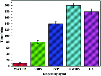
Fig. 1 shows the centrifugation time required to stratify MWCNTs in different dispersants. The results demonstrate that it takes the longest time to stratify a suspension of MWCNTs dispersed in TNWDIS, and delamination occurred after 200 minutes, showing that the suspension has excellent stability. GA is second, PVB and SDBS show successively decreased times, and water is the worst. Therefore, the addition of a dispersant facilitates the dispersion of the MWCNTs in the aqueous system, and different dispersing agents have different dispersion effects. TNWDIS can be absorbed on the surfaces of MWCNTs, forming micelles around the MWCNTs and inhibiting their aggregation. The micelles formed during this process contribute to exfoliating individual MWCNTs from bundles through electrostatic repulsion or steric hindrance effects.30 The results indicate that TNWDIS should be selected as the dispersant for MWCNTs due to it showing the best dispersion effects.
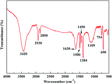
![[double bond, length as m-dash]](https://www.rsc.org/images/entities/char_e001.gif) C stretching vibration of the graphite structure in the MWCNT framework.54 This is caused by the five-membered ring or seven-membered ring at the turning point or seal of the MWCNTs. The peak at 3420 cm−1 is assigned to the –OH stretching vibration of TNWDIS. The peaks at 2930 cm−1 and 2850 cm−1 are ascribed to the stretching vibrations of –CH2- and –CH3-groups in TNWDIS. The peaks at 1500 cm−1 and 1450 cm−1 correspond to the C
C stretching vibration of the graphite structure in the MWCNT framework.54 This is caused by the five-membered ring or seven-membered ring at the turning point or seal of the MWCNTs. The peak at 3420 cm−1 is assigned to the –OH stretching vibration of TNWDIS. The peaks at 2930 cm−1 and 2850 cm−1 are ascribed to the stretching vibrations of –CH2- and –CH3-groups in TNWDIS. The peaks at 1500 cm−1 and 1450 cm−1 correspond to the C![[double bond, length as m-dash]](https://www.rsc.org/images/entities/char_e001.gif) C stretching of the aromatic structure deriving from TNWDIS, and the observed peaks at 754 cm−1 and 690 cm−1 are characteristic of the benzene ring. Peaks from C–O–C stretching are observed at 1384 cm−1 and 1109 cm−1 in TNWDIS. The Raman spectrum of MWCNTs (Fig. S2†) demonstrates two characteristic peaks. One peak at 1340 cm−1 is attributed to the disorder-induced mode (D band). The other peak at 1610 cm−1 is ascribed to the graphite mode (G band) in the MWCNT structure.48 In addition, the ID/IG ratio is 1.69, suggesting that the incorporation of TNWDIS increases lattice disorder in the MWCNTs and modifies the MWCNT surfaces.
C stretching of the aromatic structure deriving from TNWDIS, and the observed peaks at 754 cm−1 and 690 cm−1 are characteristic of the benzene ring. Peaks from C–O–C stretching are observed at 1384 cm−1 and 1109 cm−1 in TNWDIS. The Raman spectrum of MWCNTs (Fig. S2†) demonstrates two characteristic peaks. One peak at 1340 cm−1 is attributed to the disorder-induced mode (D band). The other peak at 1610 cm−1 is ascribed to the graphite mode (G band) in the MWCNT structure.48 In addition, the ID/IG ratio is 1.69, suggesting that the incorporation of TNWDIS increases lattice disorder in the MWCNTs and modifies the MWCNT surfaces.
3.2 The effects of MWCNTs on the rheological properties of oil well cement slurry
In order to investigate the effects of the addition of different amounts of MWCNTs on the rheological properties of oil well cement slurry, rheological measurements were performed using a six-speed rotational viscometer. The experimental results are shown in Table 2. The water-to-cement ratio was 0.44. MWCNTs were dispersed with TNWDIS. The TNWDIS content added was approximately 20% of the weight of the MWCNTs. The shear stress values from left to right correspond to readings at rotational speeds of 600 rpm, 300 rpm, 200 rpm, 100 rpm, 6 rpm and 3 rpm, respectively.| Number | MWCNT content (wt%) | Cement slurry density (g cm−3) | Cement slurry volume (cm3) | Shear stress values | n | K (Pa s) |
|---|---|---|---|---|---|---|
| 1 | 0.00 | 1.90 | 350 | 96/75/61/47/25/20 | 0.43 | 2.70 |
| 2 | 0.05 | 1.90 | 350 | 65/51/36/20/8/2 | 0.85 | 0.13 |
| 3 | 0.25 | 1.90 | 350 | 70/36/26/16/5/3 | 0.74 | 0.18 |
| 4 | 0.50 | 1.90 | 350 | 104/65/54/31/20/10 | 0.67 | 0.50 |
| 5 | 1.0 | 1.90 | 350 | 140/100/72/49/17/13 | 0.65 | 0.89 |
| 6 | 2.0 | 1.90 | 350 | 160/121/103/64/19/13 | 0.58 | 1.66 |
The results in Table 2 indicate that all slurries exhibit obvious shear thinning. The flow index n decreases slowly, and the consistency coefficient K increases with an increase in the MWCNT content. The addition of MWCNTs has a great influence on the rheological properties of oil well cement slurry. When the MWCNT content added is controlled between 0.05 wt% and 1.0 wt%, the rheological properties of the cement slurry are favorable and satisfy construction requirements, indicating that an optimum mass concentration range of MWCNTs is needed to achieve the ideal rheological effects. However, when the addition of MWCNTs exceeds 1.0 wt%, the dispersion degree of the MWCNTs declines and more MWCNTs tend to agglomerate, so the rheological properties are affected obviously.
3.3 The effects of MWCNTs on the fluidity of oil well cement slurry
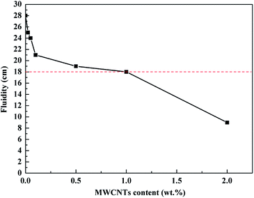
In an oil well cementing project, the fluidity of the cement slurry is generally required to be higher than 18 cm in order to facilitate pumping. The make-up of the oil well cement slurry used in these experiments is identical to that used in the above section. The fluidity experimental results are shown in Fig. 4. The incorporation of MWCNTs into the cement slurry reduces the fluidity of the cement slurry. The fluidity declines gradually with an increase in the amount of MWCNTs. The reason for this is that MWCNTs act as nucleation sites to accelerate the hydration reaction.55 When the amount of MWCNTs added is 0.025 wt%, the fluidity is 25 cm, which is beneficial for the fluidity of cement slurry. The fluidity of the cement slurry is kept above 18 cm as the amount of MWCNTs is controlled at less than 1.0 wt%. A MWCNT content of less than 0.50 wt% is more economical and suitable, and it can meet the on-site pumping requirements. When the MWCNT dosage is more than 1.0 wt%, the fluidity of the cement slurry is less than 18 cm and does not meet cementing requirements. Therefore, in order to ensure the smooth pumping of oil well cement slurry, the addition of MWCNTs should be preferably less than 0.50 wt%.3.4 Compressive strength of the MWCNT cementitious nanocomposites
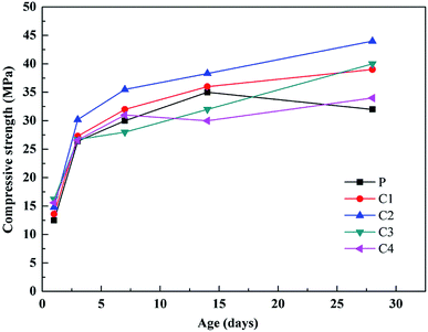
| Sample | Oil well cement (g) | MWCNT content (wt%) | Water-cement ratio (w/c) | Compressive strength (1 day, MPa) | Compressive strength (3 days, MPa) |
|---|---|---|---|---|---|
| P | 800 | 0.00 | 0.44 | 12.5 | 26.4 |
| C1 | 800 | 0.025 | 0.44 | 13.6 | 27.3 |
| C2 | 800 | 0.05 | 0.44 | 14.8 | 30.2 |
| C3 | 800 | 0.10 | 0.44 | 16.2 | 26.7 |
| C4 | 800 | 0.50 | 0.44 | 15.6 | 26.6 |
3.5 Flexural strength of the MWCNT cementitious nanocomposites
| Sample | Oil well cement (g) | MWCNT content (wt%) | Water-cement ratio (w/c) | Flexural strength (1 day, MPa) | Flexural strength (3 days, MPa) |
|---|---|---|---|---|---|
| P | 800 | 0.00 | 0.44 | 3.5 | 5.1 |
| C1 | 800 | 0.025 | 0.44 | 3.7 | 5.6 |
| C2 | 800 | 0.05 | 0.44 | 4.0 | 6.1 |
| C3 | 800 | 0.10 | 0.44 | 4.3 | 7.0 |
| C4 | 800 | 0.50 | 0.44 | 4.2 | 6.9 |
3.6 Uniaxial and triaxial mechanical properties
In this experiment, uniaxial and triaxial mechanical property measurements were conducted using the sample C2 (the addition of 0.05 wt% MWCNTs). A Φ25 × 50 mm sample designed for testing was cured in a water bath at 80 °C for 2 days. The test temperature was 25 °C. Sample P was a pure cement sample, used as a comparative sample. The results are shown in Table 5 and Fig. S3.†| Sample | Lithology | Confining pressure (MPa) | Poisson's ratio | Elastic modulus (GPa) | Peak strength (MPa) |
|---|---|---|---|---|---|
| C2 | Cement stone | 0.10 | 0.64 | 7.17 | 38.6 |
| C2 | Cement stone | 20 | 0.30 | 6.59 | 44.7 |
| P | Cement stone | 0.10 | 0.21 | 8.86 | 35.9 |
| P | Cement stone | 20 | 0.39 | 10.20 | 48.1 |
As can be seen in Table 5, the elastic moduli of the cementitious samples decline upon the addition of MWCNTs; meanwhile, the peak strengths decrease within a certain range. Fig. S3a† shows that the axial strain of the MWCNT/cement sample C2 is greater than that of the pure sample P (Fig. S3b†) when subjected to uniaxial stress. The cementitious nanocomposite is in an elastic deformation stage due to the low stress, and the stress–strain curve is almost linear. It can be calculated that the elastic modulus of the MWCNT/cement sample C2 is 7.17 GPa, which is a reduction of 19.07% compared with the pure sample P. In order to simulate the stress environment downhole, a triaxial stress loading method is adopted. From the triaxial stress–strain curve in Fig. S3c,† the axial strain of sample C2 is much higher than that of pure sample P (Fig. S3d†) under triaxial stress. It can be seen that the elastic modulus (6.59 GPa) is reduced by 35.39% compared with pure cement P. Sample P shows typical brittle failure, while sample C2 presents strong plastic deformability. The experimental results indicate that the MWCNTs can effectively reduce the elastic modulus of the cement composite and have a toughening effect on the cement composite.
3.7 XRD analysis
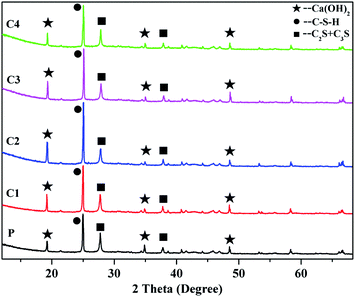
The XRD patterns of cement composites with different MWCNT content values, after 28 days of curing, are shown in Fig. 7. Since the added amounts of MWCNTs in the cement matrix are all rather small, there are no characteristic peaks corresponding to MWCNTs in the XRD patterns. Therefore, this figure depicts that none of the samples demonstrate any major differences between their diffraction patterns, indicating that no new phases are formed in the MWCNT cementitious nanocomposites compared with the pure cement sample. However, the intensities of the peaks relating to calcium-silicate-hydrate (C–S–H gel), calcium hydroxide (Ca(OH)2), tricalcium silicate (C3S) and dicalcium silicate (C2S) change a lot.57 The diffraction peaks of Ca(OH)2 are located at 2θ values of around 18.7°, 35° and 48.5°, respectively. The main peak intensities of Ca(OH)2 at 18.7° in samples C1, C2, C3, and C4 increase by 41.9%, 72.5%, 54.4%, and 23.2%, respectively, compared with pure cement P, which illustrates that the incorporation of MWCNTs promotes the cement hydration process. Meanwhile, the C–S–H gel peak intensities of samples C1, C2, C3, and C4 at a 2θ angle of 25° are 18.4%, 56.1%, 32.8%, and 9.6% higher, respectively, than that of pure cement P. Indeed, such results show a similar tendency to the compressive and flexural strength changes after 28 days. This shows that MWCNTs serve as nucleation sites, so that more C–S–H gel is generated in the hydration product. The dense C–S–H structure can improve the load-transfer capacity between the cement matrix and MWCNTs, thus contributing to the strengths of samples. In addition, the diffraction peaks at 27.5° and 37.7° arise from unhydrated products, such as C3S and C2S. It can be seen that the peak intensities of C3S and C2S in the MWCNT nanocomposites are lower than in pure cement P at a 2θ angle of 27.5°, indicating the higher hydration degree of the MWCNT/cement nanocomposites. The reason for this phenomenon is that the MWCNTs can prompt hydration reactions involving C3S and C2S, transforming C3S and C2S into C–S–H gel. The XRD analysis results show that the differences in diffraction peak intensities are mainly affected by the MWCNT content in cement. Therefore, the presence of MWCNTs enhances the formation of C–S–H gel and facilitates the hydration process in cement samples.3.8 Pore structure analysis
The pore structure determines the quality and performance of the MWCNT/cement nanocomposites. The mechanical properties are directly related to the pore structure, given that high porosity suggests a low compaction degree and inhibits the mechanical strength and durability of cement-based materials. The pore structures of the MWCNT reinforced cementitious materials are characterized using the total porosity and pore size distribution data. According to the literature,57 pores in cementitious materials are classified as innocuous pores (<20 nm in diameter), less harmful pores (20–50 nm), harmful pores (50–200 nm) and more harmful pores (>200 nm). Here, it's worth noting that decreasing the ratio of pores greater than 50 nm in diameter is more favorable for improving the performances of MWCNT/cement nanocomposites.58The total porosity and pore size distribution data from MWCNT/cement composites of different ages are shown in Fig. 8. The total porosities of samples P, C1, C2, C3, and C4 after 1 day are 35.2%, 33.9%, 32.7%, 30.5% and 32.2%, respectively, while the total porosities of samples P, C1, C2, C3, and C4 after 28 days are 19.4%, 17.7%, 16.3%, 17.0% and 18.6%, respectively. The results in Fig. 8 show that the total porosity of every sample tends to reduce as the curing age increases; the addition of MWCNTs also leads to a decrease in the total porosity compared with a pure cement sample P of the same curing age. The trends are similar to the changes in mechanical properties. The lowered total porosities indicate that the pores in the MWCNT/cement samples are filled with the continuously formed hydration products; MWCNTs can fill the large voids and promote the hydration process between voids and unhydrated cement, making the cement composites more compact.
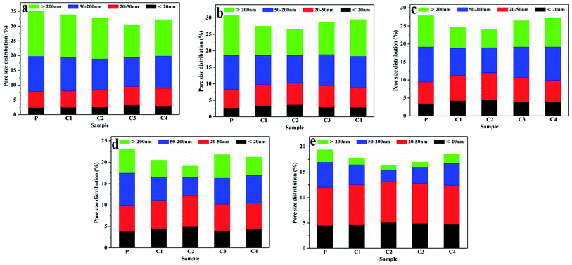 | ||
| Fig. 8 The total porosity and pore size distribution data of MWCNT/cement samples at different ages ((a): 1 day; (b): 3 days; (c): 7 days; (d): 14 days; (e): 28 days). | ||
The incorporation of MWCNTs not only affects the porosities of the cement composites, but it also influences the pore size distribution at different curing ages. As can be seen from Fig. 8a, the percentage of pores larger than 50 nm in diameter is greater than that of pores with a diameter less than 50 nm. Compared with the pure cement sample P, the percentage of pores with a diameter larger than 50 nm decreases by 5.5%, 11.3%, 23.4% and 15.0% in samples C1, C2, C3, and C4, respectively, after 1 day. As the curing age increases from 3 to 14 days (Fig. 8b–d), the percentage of pores with a diameter larger than 50 nm in the cement composites decreases gradually and the percentage of pores less than 50 nm in diameter increases accordingly. Meanwhile, the ratio of pores smaller than 50 nm in samples C1, C2, C3, and C4 is more than that in the pure cement sample P. After 28 days, the pores with a diameter of less than 50 nm in samples P, C1, C2, C3 and C4 account for 61.9%, 70.6%, 80.4%, 75.3%, and 66.7% of the total porosity, respectively (Fig. 8e). The results indicate that the number of pores with a diameter of less than 50 nm in the cement samples increases significantly compared to at an early curing age, and MWCNT addition can reduce the proportion of pores larger than 50 nm in diameter at every curing age. The pore size distribution phenomenon can be ascribed to filling effects of MWCNTs and hydration products, facilitating the transformation of detrimental pores (diameter >50 nm) to less harmful pores (diameter <50 nm). Therefore, the presence of MWCNTs is able to optimize the pore size distribution within the matrix, further enhancing the mechanical strengths of the MWCNT/cement nanocomposites.
3.9 Strengthening and toughening mechanism
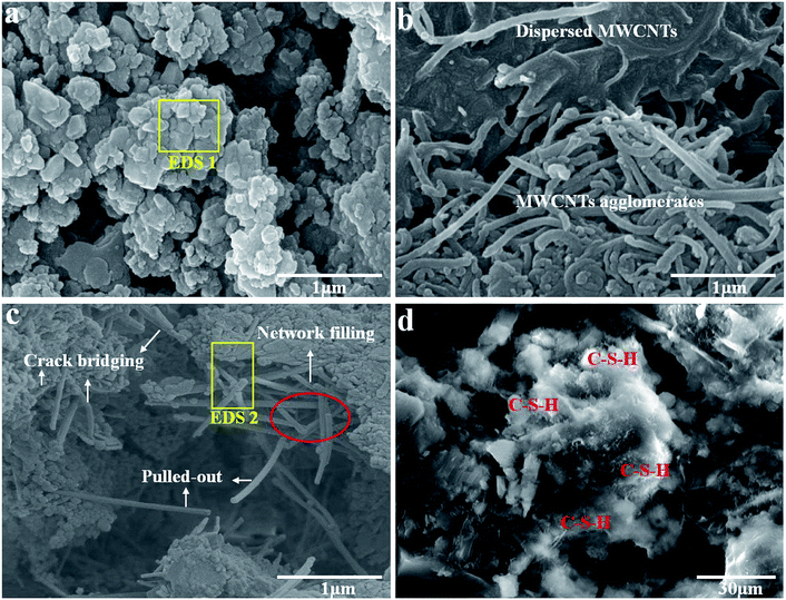
SEM images of the fracture surface morphologies of a pure cement sample and the MWCNT/cement sample C2 after 28 days are shown in Fig. 9. Fig. 9a exhibits a micrograph of the pure cement matrix, revealing typical brittle fractures with poor resistance towards rupturing or cracking. The major elemental components of the pure cement matrix are Ca, Si, O, Al, and K (Fig. S4a†). Fig. 9b presents an SEM image of a cement sample containing MWCNTs without dispersion. The MWCNTs are dispersed poorly in the matrix. The MWCNTs are intertwined with each other and there is a large MWCNT agglomerate area. At the same time, the interface defects between the MWCNTs and the cement matrix ultimately lead to a decrease in the strength of the cement composite. Fig. 9c shows a micrograph of a MWCNT/cement sample with the assistance of TNWDIS for dispersion, with EDS spectra results shown in Fig. S4b.† The element C is found to be present in Fig. S4b,† demonstrating that the MWCNTs have been integrated into the cement matrix. It can be seen from Fig. 9c that the MWCNTs are well dispersed in the cement matrix, and the ends of the MWCNTs are raised on the surface, indicating that the MWCNTs can be effectively dispersed. The surfactant TNWDIS weakens the van der Waals forces between the MWCNTs and enhances their chemical compatibility with the cement matrix, thus resulting in efficient debundling and the satisfactory dispersion of the MWCNTs in cement. In addition, fibrous MWCNTs are embedded in the cement sample by means of network filling, crack bridging and pulling out, to form a three-dimensional network structure. The network structure exhibits plastic deformation features, which can play a supporting role in the cement stability. When the MWCNT/cement sample is fractured by an external force, the direction of crack development is perpendicular to the MWCNTs; MWCNTs are pulled out and exfoliated from the cement matrix. During the pulling out process, the friction force between the MWCNTs and the cement matrix causes any energy for further crack development to be dissipated.59 The presence of the MWCNTs inhibits cracks from propagating at the nanoscale, increases the connection area of the internal structure and provides high fracture resistance under an external load.60 This is the mechanism behind the reinforcing and toughening properties of the MWCNTs (Fig. 10). Macroscopically, the mechanical properties of the cement nanocomposites are improved. Fig. 9d gives a microscopic view of the cement hydration products, and the hydration products are relatively abundant. It is noteworthy that the incorporation of MWCNTs facilitates the hydration of cement in the composite, which is in accordance with other literature studies.30,45 MWCNTs are assumed to serve as nucleation sites for the formation of C–S–H gel, and the C–S–H gel appears to form preferentially around the MWCNTs, so as to accelerate the formation rate of C–S–H. Direct nucleation at the MWCNTs produces a dense C–S–H structure, which forms as a coating along the MWCNT surfaces (Fig. 10); this can enhance the load-transfer capacity between the MWCNTs and the cement matrix. Also, the MWCNTs serve as fillers in the voids, making the structures of the hydration products more compact.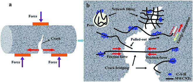 | ||
| Fig. 10 The reinforcing and toughening mechanism of MWCNTs in cementitious nanocomposites under an external load: (a) a schematic illustration; and (b) a higher magnification schematic image. | ||
4. Conclusions
In this paper, MWCNTs were applied to oil well cement to form MWCNT reinforced oil well cement-based nanocomposites for oil and gas well engineering. The effects of MWCNTs on the performances of cementitious nanocomposites were studied. TNWDIS is preferred as the dispersant for the MWCNTs. The fluidity of oil well cement slurry declines with an increase in the MWCNT content, and the addition of MWCNTs is controlled preferably below 0.50 wt% to meet the construction requirements for oil well cement slurry. For a cement sample with 0.05 wt% MWCNTs, the 28 day compressive strength is increased by 37.50% and the 28 day flexural strength is increased by 45.79% compared with pure cement. The elastic moduli of a 0.05 wt% MWCNT cementitious nanocomposite are reduced by 19.07% and 35.39%, respectively, in uniaxial and triaxial mechanical experiments, showing an improvement in toughening effects compared with the pure cement matrix. XRD and pore structure analyses indicate that the addition of MWCNTs can accelerate the hydration process, increase the amount of hydration products and optimize the pore size distribution within the matrix. Meanwhile, MWCNTs can play a role in strengthening and toughening cement samples by means of network filling, pulling out, crack bridging and a C–S–H phase. The presence of MWCNTs provides a high resistance to fracture under an external load, prevents crack growth at the nanoscale and impedes the generation and propagation of micro-cracks. Therefore, the application of MWCNT reinforced nanomaterials in oil well cement will effectively facilitate the development of oil field cementing.Conflicts of interest
There are no conflicts to declare.Acknowledgements
The research described in this paper was financially supported by the National Natural Science Foundation of China (Grant No. 51674270), the National Science and Technology Major Project (2017ZX05009-003), the Major Project of the National Natural Science Foundation of China (No. 51490650) and the Foundation for Innovative Research Groups of the National Natural Science Foundation of China (Grant: No. 51521063).References
- I. P. G. Silva, A. A. Aguiar, V. P. Rezende, A. L. M. Monsores and E. F. Lucas, J. Pet. Sci. Eng., 2018, 161, 468–475 CrossRef CAS.
- C. Jia, Pet. Explor. Dev., 2017, 44, 1–10 CrossRef.
- Q. Li, H. Xing, J. Liu and X. Liu, Petroleum, 2015, 1, 8–15 CrossRef.
- G. Quercia, H. J. H. Brouwers, A. Garnier and K. Luke, Mater. Des., 2016, 96, 162–170 CrossRef CAS.
- M. Li, S. Deng, Y. Yu, J. Jin, Y. Yang and X. Guo, Constr. Build. Mater., 2017, 135, 59–67 CrossRef CAS.
- A. Srivastava, R. Ahmed and S. Shah, J. Pet. Sci. Eng., 2018, 170, 218–230 CrossRef CAS.
- J. Konkol and G. Prokopski, Constr. Build. Mater., 2016, 123, 638–648 CrossRef CAS.
- M. Heikal, H. El-Didamony, T. M. Sokkary and I. A. Ahmed, Constr. Build. Mater., 2013, 38, 1180–1190 CrossRef CAS.
- O. Sengul, Constr. Build. Mater., 2016, 122, 649–658 CrossRef CAS.
- S. S. Joshi, N. Thammishetti, S. S. Prakash and S. Jain, ACI Struct. J., 2018, 115, 1575–1588 Search PubMed.
- K. Holschemacher, T. Mueller and Y. Ribakov, Mater. Des., 2010, 31, 2604–2615 CrossRef CAS.
- S. A. Yildizel, O. Timur and A. U. Ozturk, Mech. Compos. Mater., 2018, 54, 251–256 CrossRef CAS.
- S. Naqvi, K. Mahmoud and E. El-Salakawy, Eng. Struct., 2017, 134, 376–389 CrossRef.
- F. Pacheco-Torgal and S. Jalali, Constr. Build. Mater., 2011, 25, 575–581 CrossRef.
- S. Fic, P. Brzyski and M. Szeląg, Ecol. Chem. Eng. S, 2013, 20, 899–907 Search PubMed.
- T. Nishiwaki, M. Koda, M. Yamada, H. Mihashi and T. Kikuta, J. Adv. Concr. Technol., 2012, 10, 195–206 CrossRef CAS.
- Y. Wang, H. C. Wu and V. C. Li, J. Mater. Civ. Eng., 2000, 12, 314–319 CrossRef CAS.
- S. Sun, X. Yu, B. Han and J. Ou, Constr. Build. Mater., 2013, 49, 835–840 CrossRef.
- K. M. Liew, M. F. Kai and L. W. Zhang, Composites, Part A, 2016, 91, 301–323 CrossRef CAS.
- M. S. Konsta-Gdoutos, Z. S. Metaxa and S. P. Shah, Cem. Concr. Compos., 2010, 32, 110–115 CrossRef CAS.
- S. Sharma and N. C. Kothiyal, RSC Adv., 2015, 5, 52642 RSC.
- L. Wang, D. Zheng, S. Zhang, H. Cui and D. Li, Nanomaterials, 2016, 6, 241 CrossRef PubMed.
- L. Senff, D. Hotza, S. Lucas, V. M. Ferreira and J. A. Labrincha, Mater. Sci. Eng., A, 2012, 532, 354–361 CrossRef CAS.
- S. Song, L. Jiang, S. Jiang, X. Yan and N. Xu, Constr. Build. Mater., 2018, 164, 663–671 CrossRef CAS.
- Z. Yang, Y. Gao, S. Mu, H. Chang, W. Sun and J. Jiang, Constr. Build. Mater., 2019, 195, 415–422 CrossRef CAS.
- M. Oltulu and R. Şahin, Mater. Sci. Eng., A, 2011, 528, 7012–7019 CrossRef CAS.
- S. Kawashima, P. Hou, D. J. Corr and S. P. Shah, Cem. Concr. Compos., 2013, 36, 8–15 CrossRef CAS.
- J. M. Makar and J. J. Beaudoin, carbon nanotubes and their applications in the construction industry. Proceedings of the 1st International Symposium on Nanotechnology in Construction, Paisley, Scotland, UK, 23-25 June, 2003, ed. Bartos P.J.M., Hughes J.J., Trtik P. and Zhu W., Royal Society of Chemistry, London, UK, 2004, pp. 331–341 Search PubMed.
- M. F. Yu, O. Lourie, M. J. Dyer, K. Moloni, T. F. Kelly and R. S. Ruoff, Science, 2000, 287, 637–640 CrossRef CAS PubMed.
- W. Li, W. Ji, F. Torabian Isfabian, Y. Wang, G. Li, Y. Liu and F. Xing, Nanomaterials, 2017, 7, 185 CrossRef PubMed.
- L. J. Sudak, J. Appl. Phys., 2003, 94, 7281–7287 CrossRef CAS.
- A. L. Materazzi, F. Ubertini and A. D'Alessandro, Cem. Concr. Compos., 2013, 37, 2–11 CrossRef CAS.
- B. Han, S. Sun, S. Ding, L. Zhang, X. Yu and J. Ou, Composites, Part A, 2015, 70, 69–81 CrossRef CAS.
- S. Xu, J. Liu and Q. Li, Constr. Build. Mater., 2015, 76, 16–23 CrossRef.
- M. S. Konsta-Gdoutos and C. A. Aza, Cem. Concr. Compos., 2014, 53, 162–169 CrossRef CAS.
- K. M. Liew, M. F. Kai and L. W. Zhang, Compos. Struct., 2017, 160, 81–88 CrossRef.
- M. Szelag, Nanomaterials, 2017, 7, 267 CrossRef PubMed.
- M. d. C. Camacho, O. Galao, F. J. Baeza, E. Zornoza and P. Garcés, Materials, 2014, 7, 1640–1651 CrossRef CAS PubMed.
- F. Sanchez and K. Sobolev, Constr. Build. Mater., 2010, 24, 2060–2071 CrossRef.
- S. Kumar, P. Kolay, S. Malla and S. Mishra, J. Mater. Civ. Eng., 2012, 24, 84–91 CrossRef CAS.
- T. Kowald, Influence of surface-modified carbon nanotubes on ultra-high performance concrete. Proceedings of the international symposium on ultra high performance concrete. University of Kassel, Germany, 13-15 September, 2004, ed. Schmidt M.; Fehling E. and Geisenhanslüke C., Kassel University Press, Kassel, Germany, 2004, pp. 195–202 Search PubMed.
- T. Nochaiya and A. Chaipanich, Appl. Surf. Sci., 2011, 257, 1941–1945 CrossRef CAS.
- Y. Sáez de Ibarra, J. J. Gaitero, E. Erkizia and I. Campillo, Phys. Status Solidi A, 2006, 203, 1076–1081 CrossRef.
- X. L. Xie, Y. W. Mai and X. P. Zhou, Mater. Sci. Eng. R Rep., 2005, 49, 89–112 CrossRef.
- F. T. Isfahani, W. Li and E. Redaelli, Cem. Concr. Compos., 2016, 74, 154–163 CrossRef.
- W. W. Li, W. M. Ji, Y. C. Wang, Y. Liu, R. X. Shen and F. Xing, Materials, 2015, 8, 8780–8792 CrossRef CAS PubMed.
- F. Ubertini, A. L. Materazzi, A. D'Alessandro and S. Laflamme, Eng. Struct., 2014, 60, 265–275 CrossRef.
- S. Musso, J. M. Tulliani, G. Ferro and A. Tagliaferro, Compos. Sci. Technol., 2009, 69, 1985–1990 CrossRef CAS.
- G. Y. Li, P. M. Wang and X. Zhao, Carbon, 2005, 43, 1239–1245 CrossRef CAS.
- A. Cwirzen, K. Habermehl-Chirzen and V. Penttala, Adv. Cem. Res., 2008, 20, 65–73 CrossRef CAS.
- ASTM C305-14, Standard practice for mechanical mixing of hydraulic cement pastes and mortars of plastic consistency, ASTM International, West Conshohocken, PA, USA, 2014 Search PubMed.
- ASTM C349-14, Standard test method for compressive strength of hydraulic-cement mortars (using portions of prisms broken in flexure), ASTM International, West Conshohocken, PA, USA, 2014 Search PubMed.
- ASTM C348-14, Standard test method for flexural strength of hydraulic-cement mortars, ASTM International, West Conshohocken, PA, USA, 2014 Search PubMed.
- F. Zhou, Y. Wang, W. Wu, T. Jing, S. Mei and Y. Zhou, Sci. Rep., 2016, 6, 38000 CrossRef CAS PubMed.
- J. M. Makar and G. W. Chan, J. Am. Ceram. Soc., 2009, 92, 1303–1310 CrossRef CAS.
- Y. J. Yim and S. J. Park, Composites Research, 2015, 28, 361–365 CrossRef.
- W. J. Long, H. D. Li, C. L. Fang and F. Xing, Nanomaterials, 2018, 8, 31 CrossRef PubMed.
- H. Ma, B. Xu, J. Liu, H. Pei and Z. Li, Mater. Des., 2014, 64, 497–502 CrossRef CAS.
- P. Yu, Z. Wang, S. Lu and P. Lai, J. Nanosci. Nanotechnol., 2019, 19, 163–169 CrossRef CAS PubMed.
- Z. Qu and G. Wang, J. Appl. Polym. Sci., 2012, 124, 403–411 CrossRef CAS.
Footnote |
| † Electronic supplementary information (ESI) available. See DOI: 10.1039/c9ra04723a |
| This journal is © The Royal Society of Chemistry 2019 |

