 Open Access Article
A low-temperature technique and new strategy for the dual growth of carbon nanotubes and nanorods through the confinement of explosive materials inside a porous structure
Osama
Saber
 *ab,
Abdullah
Aljaafari
 a,
Adil
Alshoaibi
a and
Aya
Osama
c
aPhysics Department, Faculty of Science, King Faisal University, Al-Hassa 31982, P. O. Box 400, Saudi Arabia. E-mail: osmohamed@kfu.edu.sa; Tel: +966-013-5899440
bPetroleum Refining, Egyptian Petroleum Research Institute, P. O. Box 11727, Nasr City, Cairo, Egypt
cChemistry Department, Faculty of Science, King Faisal University, Al-Hassa 31982, P. O. Box 400, Saudi Arabia
First published on 25th September 2019
Abstract
In this paper, we report a low temperature technique and new strategy for the dual growth of carbon nanotubes (CNTs) and nanorods (CNRs) with alumina nanoparticles to avoid the high temperature required for CNT and CNR production and their assembling behaviour. In this trend, X-ray diffraction and thermal analysis indicated that the porous system of aluminium species was prepared and saturated with the crystalline structure of ammonium nitrate to act as a solid explosive composite and caused alcohol decomposition inside a pressurized vessel at 250 °C. TEM images and the Raman results confirmed that the CNTs had grown at 250 °C through the decomposition of methanol inside the boehmite structure. Also, the TEM images revealed that the growth of CNTs depended on the ratio between the methanol and the solid explosive. By calcination at 600 °C, the Raman results indicated that the CNTs became more ordered and had fewer defects. In the case of changing methanol to ethanol, the results indicated that methanol was more favorable than ethanol for growing CNTs by this technique. Also, it indicated that ethanol was a good source for producing carbon nanorods. Finally, we concluded that this was probably the first time that carbon nanotubes or nanorods had been prepared at 250 °C and their aggregations prevented through their dual growth with alumina nanoparticles. This dual growth approach is a very promising strategy for building homogeneous nanocomposites based on carbon nanotubes and nanorods.
Introduction
Carbon nanotubes (CNTs)1 and nanorods (CNRs)2 possess three-dimensional nanostructures and have attracted extensive attention because of their potential applications.2,3 These applications are due to their amazing properties, such as high thermal conductivity, excellent mechanical properties and high electrical conductivity.4,5 As a result, their applications have been extended to include composite materials and catalysts,6–9 field emitters and sensors,10–13 conductive films and tips for scanning probe microscopy,14–17 biomaterials,18 energy storage media19,20 and nano-electronic devices.21,22In the case of CNTs, they could be produced by various synthesis techniques: chemical vapour deposition (CVD),23 flame synthesis,24 laser ablation25 and arc discharge.1 CVD uses a catalyst to produce CNTs through the decomposition of hydrocarbons in the temperature range of 700–1200 °C.23 Arc discharge depends on two electrodes without any metal catalyst. In laser ablation, an intense laser beam is used to produce CNTs.
The principal drawback of these conventional techniques is the need for high temperature or high consumption of energy to produce the CNTs. In addition, very expensive arrangements are required with these methods, such as electrodes, laser beams and catalysts. Furthermore, the produced CNTs have strong intermolecular interactions, which lead to the formation of strong aggregates, reducing their accessible surface area and limiting their applications.26
Several researchers6–22 have attempted to disperse CNTs or CNRs in an alumina matrix to enhance the fracture toughness of structural ceramics only by the direct mixing of CNTs or CNRs with alumina powder. However, no-one has succeeded in growing CNTs with CNRs during alumina preparation because the growth of CNTs or CNRs needs a temperature higher than 700 °C and the alumina species start to grow below 400 °C. Therefore, achieving alumina nanocomposites with a uniform dispersion of CNTs or CNRs is difficult because of the basic features of CNTs, such as their assembling behaviour. These features cause inhomogeneous dispersion and a weak reinforcing effect in the final product. Furthermore, severe treatment conditions for the CNTs or CNRs to avoid heterogeneous dispersion, such as high energy milling, acid treatment and continuous sonication, lead to damages and a deterioration of the properties of the produced composite.26
In order to improve the distribution of CNTs in the alumina matrix, Calvert8 used the direct mixing of CNTs with alumina powder without a non-aqueous medium. Kong et al.9–11 prepared CNTs on alumina powder using a CVD technique. Liu et al.12 induced appropriate charges on CNTs and alumina by colloidal processing for optimal dispersion. Bi et al.13 dispersed functionalized CNTs in an aluminium nitrate solution. Nguyen et al.14,15 added CNTs to the boehmite structure. Martin et al. and Che et al.18,19 modified the surface of the CNTs by acid and surfactant treatments before adding into the alumina matrix.
Therefore, there is a need for a novel strategy to prepare CNTs or CNRs during the preparation of aluminium oxide species at low temperatures to avoid the drawbacks of the above techniques.
Some researchers27–29 have used unusual techniques for producing nanoscale materials. Kroke et al.30 prepared CNTs using a detonative decomposition method. Lu et al.31,32 used picric acid, which is considered an explosive material to synthesize homogenous CNTs. Utschig et al.33 studied the effect of transition metals and the degree of confinement of the explosive decomposition of an energetic precursor on the formation of carbon nanotubes through ignition by a piezoelectric spark generator. Wang et al.34 investigated the effect of sulphur on the growth of carbon nanotubes using detonation-assisted chemical vapour deposition. Recently, Zhao et al.35,36 fabricated carbon nanotubes by a gaseous detonation method through the ignition of a mixed gas consisting of ferrocene vapour, methane and oxygen. In the same year, Huber et al.37 used the high explosive detonation of composition B-3 (40% TNT, 60% RDX) for producing novel nanocarbons.
Those researchers indicated that detonation and explosive detonation can be considered as useful techniques to reduce the high external energy required for producing CNTs. Although, these researchers used gaseous and liquefied explosives, they did not succeed when the temperature was decreased below 300 °C. Also, they did not solve the problem of the aggregating behaviour of CNTs. Therefore, we intended to synthesize CNTs and CNRs at a lower temperature avoiding their aggregating behaviour through a new strategy. This strategy depended on the dual growth of CNTs and CNRs with alumina nanoparticles through the confinement of solid explosives inside the porous structures of alumina species. Alumina nanoparticles can prevent the aggregation of CNTs. At the same time, the porous structure of alumina will act as a confined space to increase the effectiveness of explosive reactions to produce CNTs and CNRs at 250 °C.
In the present study, a crystalline explosive material was prepared inside the porous structure of boehmite. The explosive material in the presence of methanol and alumina species can act as a composite solid propellant, which is extensively used in military missions. A dual growth of CNTs and CNRs with alumina nanoparticles was thus studied for the first time through the decomposition of methanol using a composite solid propellant. Also, the effect of methanol as a source of carbon and as a fuel for the explosive reactions was investigated by traditional nanomaterial characterization tools, such as scanning and transmission electron microscopy and Raman spectroscopy. Moreover, X-ray diffraction, infrared spectroscopy and thermal analysis were used to confirm the dual growth of CNTs and CNRs within the alumina structure. Furthermore, the growth process of CNTs and CNRs was studied by changing the source of carbon from methanol to ethanol.
Results
Production of explosive solid composites
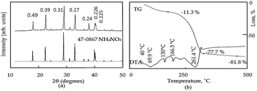
The X-ray diffraction diagram of the prepared gel is shown in Fig. 1a. The XRD diagram shows sharp reflections at 2θ = 17.9°, 22.5°, 28.9°, 32.9°, 37.8°, 39.9°, and 40.2° agreeing with the spacings at 0.493, 0.395, 0.308, 0.272, 0.248, 0.226 and 0.225 nm for the crystalline phase of ammonium nitrate in the JCPDS file no. 47-0867.No peaks were observed for the aluminium species. This implies that the dried gel, produced from the reaction of ammonium bicarbonate with aluminium nitrate, consisted of the amorphous form of aluminium hydroxide and the crystalline structure of ammonium nitrate, as indicated in the following reaction:
| Al(NO3)3 + 3NH4HCO3 → 3NH4NO3 + Al(OH)3 + 3CO2 |
Thermal analysis of the dried gel was used to determine the saturated amount of ammonium nitrate inside aluminium hydroxide. Differential thermal analysis (DTA) and thermal gravimetric analysis (TGA) of the dried gel are shown in Fig. 1b. The DTA curve shows five endothermic peaks, agreeing with the five phase modifications of ammonium nitrate. The first three endothermic peaks with temperatures at 39 °C, 69.9 °C and 130.1 °C, respectively, verified that there were three phase state transitions of ammonium nitrate, as reported in the literature.37 The fourth endothermic peak at 166.5 °C represented the absorption of heat for the melting of ammonium nitrate. The fifth endothermic peak at 261.4 °C showed the heat absorption for the gradual decomposition of ammonium nitrate and the dehydroxylation reaction of aluminium hydroxide. After this temperature, there was a sharp exothermic peak for the complete decomposition of ammonium nitrate. The corresponding TG curve showed 77.7% weight loss at 299 °C. Above 299 °C, crystallization of aluminium oxide was observed through the presence of one broad exothermic peak and a small weight loss of 4%. Finally, the residual weight reached 18.3%. This suggests that aluminium hydroxide was saturated with three times its weight of ammonium nitrate, agreeing with the above reaction.
A composite solid propellant, which is extensively used in military missions, is composed mainly of a crystalline oxidizer, binder and metallic fuel.38 Therefore, the prepared dried gel could act as a composite solid propellant. Aluminium oxide hydroxide is used as a binder and can also act as a fuel in certain conditions.39 Ammonium nitrate, which is the principal component of most industrial explosives, could be used as a solid propellant oxidizer in the presence of alcohol.40,41
Growth of carbon nanotubes
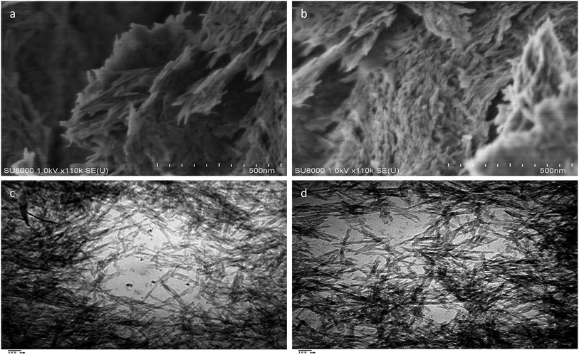
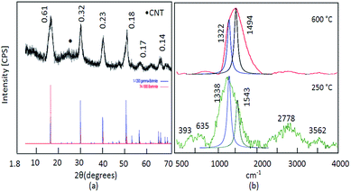
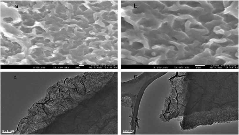
SEM analysis of ACNT-1 showed that aggregates of carbon nanotubes were obtained by the reaction of 100 g of the prepared gel with methanol, as shown in Fig. 2a and b. The formation of carbon nanotubes was confirmed by the TEM images. Fig. 2c and d reveal a large amount of CNTs with the dispersed nanoparticles. Also, individual carbon nanotubes could be observed in the TEM images.The X-ray diffraction pattern showed that the sample ACNT-1 had clear peaks, matching well with the standard diffraction peaks of the boehmite structure (JCPDS card no. 74-1895) as shown in Fig. 3a. It is known that the boehmite structure is one of the species of aluminium oxide, with the ideal form of AlOOH. Boehmite has layered deformed octahedral structures with aluminium ions near the centre. These layers are connected together through the hydrogen bonds among the hydroxyl ions. Also, the sample showed the characteristic reflections of boehmite at 2θ = 14.4°, 28.3°, 38.4°, 48.9°, 55.1° and 64.2° agreeing with the d-spacings of 0.61, 0.32, 0.23, 0.18, 0.17 and 0.14 nm, respectively, as shown in Fig. 3a. Also, the broad weak peak at 2θ = 26.1° was due to the CNTs.1,13 The weakness of the CNT peak in the diagram is related to the homogeneous distribution of CNTs inside the matrix of the boehmite. The XRD results concluded that aluminium hydroxide was dehydrated forming aluminium oxide hydroxide. At the same time, methanol was decomposed to build CNTs.
Carbon nanotubes have been widely characterized by Raman scattering.1,2 Two main groups of bands were observed in the Raman spectra of ACNT-1, as shown in Fig. 3b. Radial breathing modes (RBMs) were observed from 100 cm−1 to 400 cm−1. The frequencies of these modes change inversely with the tube diameters.42–44
As shown in Fig. 3b, RBM was observed at 393 cm−1. In the interval from 1100 cm−1 to 3400 cm−1, the second-order Raman spectra of CNTs could be observed. The Raman spectra showed first-order bands of CNTs, which are labelled as D and G peaks. The “D” band is a sign of defects in nanotubes or disorder in the graphitic lattice. It was observed at 1200–1300 cm−1. The “G” mode was found in the 1500–1600 cm−1 range. This was due to the tangential stretching modes of the tubes, indicating the ordering of the CNTs. As shown in Fig. 3b, the overlap between the D and G bands are focused at 1338 cm−1 as a broad band, corresponding to a lower degree of graphitic ordering of CNTs.44,45 This overlap is due to the hybrid structure between the CNTs and aluminium oxide, as Inbaraj et al.46 reported that the characteristic Raman peaks of aluminium oxides could be observed at 1373 cm−1 and 1403 cm−1. This means that the D and G bands of CNTs are adjacent to the alumina bands and almost merged with them to show a broad band at 1338 cm−1. Second-order bands of Raman spectra were observed in the region between 2400 cm−1 and 3400 cm−1. They showed two bands attributed to the overtone of the “D” and “G” modes (2D and 2G). Therefore, at the high frequencies of the Raman spectra of ACNT-1, two Raman bands at 2778 cm−1 and 3562 cm−1 can be observed in Fig. 3b. Also, the Raman spectrum of aluminium hydroxide was observed at 635 cm−1.
By calcination at 600 °C, Fig. 3b shows the disappearance of the disorder mode (2D). At the same time, the overlap between the D and G bands is shifted to be focused at 1494 cm−1, indicating that the CNTs became much ordered and possessed significantly lower defects because the calcination temperature converted the amorphous and unstable carbon to carbon dioxide.46
By using Gaussian functions, the D and G bands of CNTs were split and observed at 1322 cm−1 and 1494 cm−1; respectively. The origin of the D band could be explained as disorder-induced features due to the lattice distortion. The D band is frequently referred to as the defect band. Its intensity relative to the G band is often used to determine the quality of nanotubes. The ID/IG ratio of pure CNTs is 0.8 to 0.9.46 In the case of the nanocomposite ACNT-1, the ID/IG ratio was 1.6, indicating a lower degree of graphitic ordering of the CNTs. After the thermal treatment at 600 °C, the ID/IG ratio became 0.85, confirming that the CNTs had become more ordered and possessed significantly lower defects.
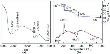
Infrared spectroscopy is a helpful technique to further confirm the growth of CNTs inside the boehmite structure. The FT-IR spectrum of ACNT-1 is shown in Fig. 4a. The bands at 3371 and 1646 cm−1 were assigned to the O–H stretching and bending vibrations, respectively. Also, the C–C vibration was confirmed by the two bands at 1412 and 1293 cm−1.38 At the low frequencies, the valence and strain vibrations of O–Al–O were detected by the bands at 775 and 605 cm−1, respectively.43
Fig. 4b shows the TGA and DSC curves of ACNT-1. Five weight losses were observed in the TGA curve. The initial weight loss was 6%, corresponding to the removal of the adsorbed water. The second weight loss was 12%, indicating the oxidation of the unstable carbon. The third and fourth weight losses occurred in the range of 200–500 °C, and were 5% and 12%, respectively. These weight losses converted ACNT-1 to a nanocomposite through the dehydroxylation of the boehmite structure. Above 500 °C, 5% of the weight was slowly lost up to 1000 °C because of the decomposition of the carbon species. Agreeing with the results of Cho et al., they reported that the decomposition of some kinds of CNTs started at slightly above 600 °C.20 The residue was 60% of the sample. In the DSC curve, three endothermic peaks could be observed at 100 °C, 482 °C and 863 °C, confirming the removal of the adsorbed water, the dehydroxylation process and decomposition of the carbon species; respectively. Also, the DSC curve showed one exothermic peak at 209 °C, agreeing with the second weight loss and confirming the oxidation of the unstable carbon.
Development of the growth process of the carbon nanotubes
In order to develop the dual growth process, ACNT-2 was prepared by lowering the amount of the dried gel to a quarter of the beginning amount. Field emission scanning electron microscopy (FESEM) observations were made to give a general view of a large region of the sample, permitting one to prove that there were CNTs in ACNT-2.FESEM images of the ACNT-2 sample, coated by a thin layer of platinum, are displayed in Fig. 5a and b. Clear images of CNTs could be seen. Fine particles were also observed in the nanoscale. These results were confirmed by transmission electron microscopy. The TEM images revealed the network structure of the alumina nanoparticles containing a uniform distribution of CNTs, as shown in Fig. 5c and d. In the same trend, CNTs could be clearly observed by the calcination of ACNT-2 at 600 °C.
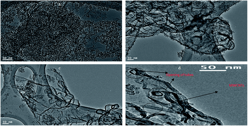
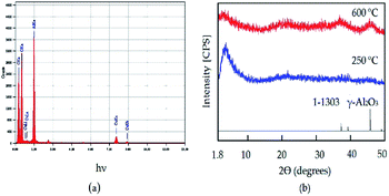
It can be seen that the carbon nanotubes were surrounded by alumina nanoparticles, as shown in Fig. 6b. This indicated that there was an interaction between the CNTs and alumina particles, which indicates that the dual growth of CNTs and alumina nanoparticles created a hybrid structure between them. This structure led to the formation of a homogeneous and interesting network structure of nanocomposites, as shown in Fig. 6a. By magnification, Fig. 6d showed that the CNTs were multi-walled carbon nanotubes with an outer diameter of 10 nm. Also, it displayed opening rings of the nanotubes. Energy-dispersive X-ray analysis (EDX) confirmed the formation of the ACNT-2 nanocomposites through the observation of clear peaks of aluminium, oxygen and carbon, as shown in Fig. 7a. Also, noting that the copper in the EDX pattern was due to the substrate. Fig. 7b shows the XRD diagrams of ACNT-2 before and after calcination. At low 2θ, there is a strong broad peak, indicating a mesoporous structure. At high 2θ, no diffraction peak of ACNT-2 could be observed, suggesting an amorphous structure of aluminium oxide. After the calcination of ACNT-2 at 600 °C, two weak peaks were observed at 37.6° and 45.8°, matching with the main peaks of gamma alumina (JCPDS card no. 1-1303), as shown in Fig. 7b. These results agreed with the SEM and TEM observations.
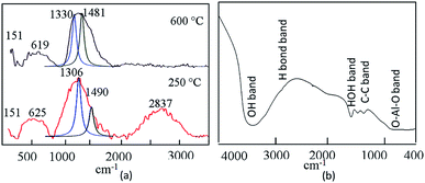
The Raman spectra of the calcined and the uncalcined ACNT-2 are shown in Fig. 8a. The uncalcined ACNT-2 revealed the radial breathing mode at about 151 cm−1. This peak position depends on the tube diameter and varies in the range of 130–400 cm−1.44 The main band, which reveals the electronic structure of the CNTs, was observed at 1490 cm−1, combined with a broad band located at 1306 cm−1, as shown in Fig. 8a. This broad peak has been associated with the sp3 carbon hybridization and is used as proof for the disorder of the aromatic system of π electrons.47,48 The broadness of this peak may be due to the hybrid structure between CNTs and alumina nanoparticles in addition to the impurities of the carbon nanorods.
The peak intensity of this disorder mode disappeared and was shifted to 1481 cm−1 by calcination at 600 °C, as shown in Fig. 8a. The peak at 1481 cm−1 was due to the C–C stretching Raman-active G mode, confirming the presence of CNTs. Also, the broadness of the G-band may be due to the presence of aluminium oxides combined with carbon nanotubes. The second-order Raman spectrum, observed between 2400 and 3400 cm−1 for the uncalcined ACNT-2 and attributed to the overtone of the disordered band (2D), disappeared following the thermal treatment. The D and G bands of CNTs of the uncalcined ACNT-2 were observed at 1306 and 1490 cm−1 using Gaussian functions. The ID/IG ratio was 1.4, indicating that the CNTs had a high degree of defects. After the thermal treatment, the ID/IG ratio of ACNT-2 decreased to 0.98, confirming that the calcination temperature improved the quality of the produced CNTs.
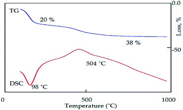
Agreeing with the results obtained from the Raman spectra, the IR spectrum of the calcined ACNT-2 confirmed the presence of CNTs, showing the C–C vibration band at 1408 cm−1, as seen in Fig. 8b. The bands located at 3464 and 1638 cm−1 were assigned to the O–H stretching and bending vibrations of the adsorbed water and alumina structure. Fig. 9 presents the thermal analyses of ACNT-2 as determined by thermogravimetric analysis (TGA) and differential scanning calorimetry (DSC). The TG diagram shows that ACNT-2 lost 38 wt% of its mass through three stages by heating up to 600 °C. These mass losses were confirmed by two peaks in the DSC diagram. The first endothermic peak, which occurred at 98 °C, was due to the dehydration reaction, while the exothermic peak around 450 °C could be assigned to the oxidation of the unstable carbon. Finally, there was a broad exothermic peak at 504 °C corresponding to the crystallization of alumina.
Effect of alcohol on the growth of the carbon nanotubes
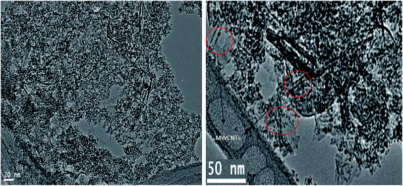
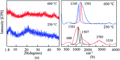
By changing the source of carbon from methanol to ethanol, CNTs and CNRs could be observed in Fig. 10. This shows the morphology of ACNT-3 before and after calcination. Large aggregates of alumina nanoparticles could be observed, as shown in Fig. 10a. Also, Fig. 10a shows that the CNTs and CNRs were homogeneously distributed through alumina nanoparticle aggregations. Following calcination at 600 °C, Fig. 10b revealed that the CNTs became clearer. An individual dispersion of these tubes was observed through the structure of alumina. The XRD patterns of ACNT-3 before and after calcination are displayed in Fig. 11a, which revealed the amorphous structure of the aluminium oxide species before calcination. After calcination at 600 °C, weak peaks of gamma alumina were observed. Fig. 11b shows the Raman spectra of ACNT-3 before and after calcination.The CNT spectrum showed an overlap between the D and G modes. The maximum intensity was observed at 1301 cm−1, corresponding to the D mode, indicating the defects and disorder of CNTs. The second-order Raman spectra were also observed as weak peaks between 2500 and 3500 cm−1. After calcination, the second-order Raman spectra disappeared. Also, the G peak, which was related with the C–C stretching mode of CNTs, became clear at 1501 cm−1, representing their crystalline order. The ID/IG ratio of the D and G bands, which was spilt out by Gaussian functions, decreased from 1.7 to 0.94 after calcination, confirming the crystalline order of the CNTs.
It is noteworthy that the radial breathing mode was not observed in the ACNT-3 sample. This indicated that carbon nanorods were the major components in this nanocomposite. This means that ethanol is not favourable for producing CNTs by this technique.
To explain the effect of alcohols on the quality of CNTs, we applied the heat of enthalpy of each alcohol. The standard heat of enthalpy of gas-phase methanol is −201.0 kJ mol−1, while for ethanol it is −235.0 kJ mol−1.49 It is reasonable to assume that the standard heat of enthalpy affects the growth rate of CNTs because an alcohol molecule having a lower absolute value for its standard heat of enthalpy is more easily decomposed. This means that methanol is more favourable than ethanol for producing longer tubes of CNTs. Consequently, the outer diameter of the methanol-based CNTs may be different from that of the ethanol-based CNTs.50
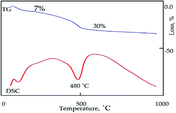
Fig. 12 shows the thermal analyses of ACNT-3. The DSC curve revealed two endothermic peaks at 100 °C and 480 °C, confirming the removal of water and the formation of gamma alumina in addition to the decomposition of the unstable amorphous carbon, respectively. Two mass losses were observed in the TGA curve, thus agreeing with the DSC results. Above 480 °C, the mass loss continued at a low rate up to 1000 °C, indicating the decomposition of the CNTs.
Mechanism of carbon nanotube growth
Several carbon sources have been used in the chemical vapour deposition technique for producing CNTs, such as hydrocarbons and alcohols.51 Maruyama et al.52 reported that alcohol is the best carbon source for the growth of CNTs on semiconductor materials. Although, the authors titled their research the low-temperature synthesis of CNTs, this low temperature in their research was 550–700 °C. Alcohols are considered as attractive sources because they produce CNTs with low impurity and are safe to handle. The generation of OH radicals during alcohol decomposition was thought to be the reason for the improved purity.4 The majority of the reported results on CNT production showed that CNTs could be prepared using CVD and alcohol as carbon sources at high temperatures of 600–900 °C.53In this research, we reported a new strategy to employ a composite solid propellant with a low temperature of 250 °C in the growth of CNTs inside a confined matrix in order to avoid the high temperature of CNT production and their assembling behaviour. Also, the confined space increases the effectiveness of the explosive reactions. In addition, the boehmite matrix participates in the explosive reaction producing a homogeneous nanocomposite. A composite solid propellant is a heterogeneous mixture of a hydrocarbon/synthetic-based fuel/binder, a crystalline oxidizer, and a metallic fuel.54 In our study, methanol or ethanol was used as a synthetic-based fuel and also acted as a binder to hold all the ingredients together.55 The crystalline oxidizer was ammonium nitrate. This is the main component of most industrial explosives.56 Several compositions of ammonium nitrate are well-known explosives, such as ammonium nitrate fuel oil. The use of ammonium nitrate in propellants is limited because of their low burning rate. Thus, it could be used in gas generators for the turbo pumps of liquid propellant rocket engines or in emergency starters for jet aircrafts.57 Metallic fuels, like aluminium hydroxide gel, assist in a more energetic and aggressive combustion of the propellant.58 This means that ammonium nitrate with aluminium hydroxide is considered a strong source for the detonation process.
The proposed mechanism for this type of CNT or CNR growth depended on two points. The first point indicated that the porous structure of the boehmite support introduced active nucleation sites for starting the growth process of CNTs. Also, aluminium oxide species catalyzed the decomposition of hydrocarbons.59 The second point indicated that the thermal decomposition of the explosive compound provided an environment for the decomposition of methanol to produce CNTs. However, auto-ignition and the explosion of ammonium nitrate may take place inside the confined spaces of the porous structure of alumina species. Obviously, no single mechanism can explain the thermal decomposition of ammonium nitrate.55 When ammonium nitrate is heated from 200 °C to 230 °C, exothermic decomposition occurs as follows:
| NH4NO3 → 2N2 + NO + 2H2O |
Above 230 °C, the decomposition occurs as per the following exothermic reaction
| NH4NO3 → 3/4N2 + 1/2NO2 + 2H2O |
The reaction pathway has been suggested when ammonium nitrate undergoes an explosion.
| 8NH4NO3 → 5N2 + 4NO + 2NO2 + 16H2O |
In our study, aluminium had a strong destabilizing effect on the thermal decomposition of ammonium nitrate.55 Therefore, aluminium hydroxide strongly promoted the thermal decomposition of ammonium nitrate at 250 °C. At the same time, the molecules of the alcohol were rapidly decomposed because of the energy that was generated from the detonation process of ammonium nitrate. The following consecutive steps take place during the explosion process to produce CNTs:
1. Formation of carbon species by the decomposition of alcohol over the boehmite structure during the explosion process.
2. Diffusion of carbon species through the porous structure of boehmite.
3. Precipitation of carbon in the form of CNTs from the saturated porous structure of boehmite with the carbon species.
The decomposition reactions of the first step may be catalyzed by aluminium species to produce hydrogen radicals and carbon species. These carbon species diffuse and are confined inside the porous structure of boehmite to attain the saturation level. At this moment, the carbon species directly assemble to form CNTs, while H2O molecules, which were produced by the hydrogen radicals, effectively prevent the oxidation of carbon species and enhance the stability of solid carbon.
The unstable carbon species or CNRs may be formed because of the unusual variation in the heat, which is essentially supplied from the energy released from the exothermic decomposition of the explosives and decreases sharply after the detonation process. Also, this is probable due to the formation of the structural defects of CNTs.
It is important to note that the chemical and physical conditions produced from the detonation method for the growth of CNTs are not similar to those of the other methods, such as in CVD. In the current process, the environment produced by detonation is relatively complex; where, the carbon species needed for the formation of CNTs are supplied on a microsecond time-scale at a high gas pressure (tens of MPa).60
This mechanism agrees with the results reported by Nepal et al.61 They studied a catalyst-free detonation method using ethylene as the hydrocarbon source and oxygen as the explosive gas. They reported that the high temperature produced from the detonation process was the main reason for the graphenic nature of the carbon produced. In addition, they hypothesized that the hydrocarbon precursor was completely decomposed by the detonation process to produce carbon atoms or ions, which quickly combined to form graphene or its products.
Experimental
Materials and methods
To study the effect of both the gel and alcohol on the growth of CNTs, two different amounts of the dried gel and two different kinds of alcohols were used in this process, as shown in Table 1.
| Sample | Dried gel | Alcohol |
|---|---|---|
| ACNT-1 | 100 g | Methanol |
| ACNT-2 | 25 g | Methanol |
| ACNT-3 | 25 g | Ethanol |
Conclusions
The present research had a dual aim for developing a new strategy for CNT growth at low temperature and producing homogeneous nanocomposites of alumina nanoparticles doped with CNTs or CNRs. In this way, aluminium species were prepared and saturated with ammonium nitrate to treat inside a pressurized vessel at 250 °C. Ammonium nitrate is an explosive compound and was used as a composite solid propellant in the growth of CNTs inside the confined matrix of the alumina species. In the case of using methanol as the source of CNTs, the SEM and TEM images revealed large aggregates of CNTs with dispersed nanoparticles. The XRD results confirmed that these nanoparticles had the boehmite structure of alumina species. The Raman results indicated that the CNTs became much ordered and possessed significantly lower defects after calcination at 600 °C. By changing the ratio between the methanol and the composite solid propellant, the growth of CNTs increased, as confirmed by the TG curves. Also, the TEM images showed that the CNTs became clearer. Following calcination at 600 °C, the Raman results indicated that the CNTs became more ordered because the high temperature removed the unstable CNTs. In the case of using ethanol instead of methanol, the CNRs were clear. After calcination at 600 °C, the TEM images showed large aggregates of alumina nanoparticles combined with CNTs and CNRs. This means that methanol is more favourable than ethanol for growing CNTs by this technique. Also, ethanol is a good source for producing CNRs. Finally, it could be concluded that the growth of CNTs or CNRs was possible at 250 °C by using an explosive solid material confined in a porous structure. Also, we introduced a novel strategy for building homogeneous CNT- or CNR-based nanocomposites to meet the special requirements of the catalysis and water purification markets.Conflicts of interest
There are no conflicts to declare.Acknowledgements
The authors thank the Deanship of Scientific Research in King Faisal University (Saudi Arabia) for funding and providing the facilities required for this research as a part of the Research Grants Program (No. 1811006).References
- C. N. He, F. Tian and S. J. Liu, J. Alloys Compd., 2009, 478, 816–819 CrossRef CAS.
- S. W. Tan, X. C. Chen, S. L. Zhai, A. Ebrahimi, T. Langrish and Y. Chen, Energy, 2018, 147, 308–316 CrossRef CAS.
- W. L. Zhang, N. Lin, D. B. Liu, J. H. Xu, J. X. Sha, J. Yin, X. B. Tan, H. P. Yang, H. Y. Lu and H. B. Lin, Energy, 2017, 128, 618–625 CrossRef CAS.
- B. Zhang, F. Kang, J. M. Tarascon and J. K. Kim, Mater. Sci., 2016, 76, 319–380 CAS.
- J. Yang, J. Guo, X. Guo and L. Chen, Mater. Lett., 2019, 236, 739–742 CrossRef CAS.
- T. Huang, H. Fang, S. Mao, J. Yu and L. Qi, Carbon, 2018, 126, 566–573 CrossRef CAS.
- T. Kinoshita, M. Karita, T. Nakano and Y. Inoue, Carbon, 2019, 144, 152–160 CrossRef CAS.
- P. Calvert, Nature, 1999, 399, 210–211 CrossRef CAS.
- M. A. S. Matos, S. T. Pinho and V. L. Tagarielli, Carbon, 2019, 146, 265–275 CrossRef CAS.
- J. Kong, N. R. Franklin, C. W. Zhou, M. G. Chapline, S. Peng and K. J. Cho, et al. , Science, 2000, 287, 622–625 CrossRef CAS.
- S. Chun, W. Son and C. Choi, Carbon, 2018, 139, 586–592 CrossRef CAS.
- C. Liu, Y. Tong, H. M. Cheng, D. Golberg and Y. Bando, Appl. Phys. Lett., 2005, 86, 223114–223115 CrossRef.
- S. Bi, X. Su, G. Hou, G. Gu and Z. Xiao, Phys. B, 2010, 405, 3312–3315 CrossRef CAS.
- C. V. Nguyen, Q. Ye and M. Meyyappan, Meas. Sci. Technol., 2005, 16, 2138–2146 CrossRef CAS.
- C. V. Nguyen, K. J. Chao, R. M. D. Stevens, L. Delzeit, A. Cassell and J. Han, et al. , Nanotechnology, 2001, 12, 363–367 CrossRef CAS.
- N. Li, Z. Chen, F. Chen, G. Hu, S. Wang, Z. Sun, X. Sun and F. Li, Carbon, 2019, 143, 523–530 CrossRef CAS.
- M. Zhang, S. L. Fang, A. A. Zakhidov, S. B. Lee and A. E. Aliev, et al. , Science, 2005, 309, 1215–1219 CrossRef CAS.
- R. Deng, Y. Zhu, J. Hou, J. C. White, J. L. Gardea-Torresdey and D. Lin, Carbon, 2019, 145, 658–667 CrossRef CAS.
- G. L. Che, B. B. Lakshmi, E. R. Fisher and C. R. Martin, Nature, 1998, 393, 346–349 CrossRef CAS.
- W. Cho, M. Schulz and V. Shanov, Carbon, 2014, 72, 264–273 CrossRef CAS.
- C. Liu, Y. Y. Fan, M. Liu, H. T. Cong, H. M. Cheng and M. S. Dresselhaus, Science, 1999, 286, 1127–1129 CrossRef CAS.
- J. Li, X. Lan, S. Lei, J. Ou-Yang, X. Yang and B. Zhu, Carbon, 2019, 145, 112–118 CrossRef CAS.
- L. Kong, X. Yin, H. Xu, X. Yuan, T. Wang, Z. Xu, J. Huang, R. Yang and H. Fan, Carbon, 2019, 145, 61–66 CrossRef CAS.
- S. Suzuki and S. Mori, Appl. Surf. Sci., 2019, 471, 587–594 CrossRef CAS.
- Y. Mo, H. Zhou, B. Zhang, X. Du, Z. Lin, W. Li, H. Y. Liu and Y. W. Mai, Appl. Surf. Sci., 2019, 465, 23–30 CrossRef CAS.
- L. Dang, Y. Hou, C. Song, Q. Lu, Z. Wang, Q. Feng, Q. Lu and F. Gao, Composites, Part B, 2019, 161, 328–335 CrossRef CAS.
- K. E. Thomson, D. T. Jiang, R. O. Ritchie and A. K. Mukherjee, Appl. Phys. A, 2007, 89, 651–654 CrossRef CAS.
- S. Eidelmann and A. Altshuler, Nanostruct. Mater., 1993, 3, 31–41 CrossRef.
- R. Boese, A. J. Matzger and K. P. C. Vollhardt, J. Am. Chem. Soc., 1997, 119, 2052–2053 CrossRef CAS.
- E. Kroke, M. Schwarz, V. Buschmann, G. Miehe, H. Fuess and R. Riedel, Adv. Mater., 1999, 11, 158–161 CrossRef CAS.
- Y. Lu, Z. Zhu, W. Wu and Z. Liu, Chem. Commun., 2002, 2740–2741 RSC.
- Y. Lu, Z. Zhu and Z. Liu, Carbon, 2004, 42, 361–370 CrossRef CAS.
- T. Utschig, M. Schwarz, G. Miehe and E. Kroke, Carbon, 2004, 42, 823–828 CrossRef CAS.
- C. Wang, L. Zhan, Y. Wang, W. Qiao, X. Liang and L. Ling, Appl. Surf. Sci., 2010, 257, 932–936 CrossRef CAS.
- T. Zhao, X. Li, Y. Wang, J. H. S. Lee and H. Yan, Mater. Res. Bull., 2018, 102, 153–159 CrossRef CAS.
- T. Zhao, X. Li and H. Yan, Combust. Flame, 2018, 196, 108–115 CrossRef CAS.
- R. C. Huber, B. S. Ringstrand, D. M. Dattelbaum, R. L. Gustavsen, S. Seifert, M. A. Firestone and D. W. Podlesak, Carbon, 2018, 126, 289–298 CrossRef CAS.
- H. L. Saunders, J. Chem. Soc., 1922, 121, 698–711 RSC.
- N. Kubota, Propellants and Explosives: Thermochemical Aspects of Combustion, Wiley-VCH Verlag GmbH & Co. KGaA, Weinheim, Germany, 2007, ISBN: 978-3-527-31424-9 Search PubMed.
- A. Davenas, J. Propul. Power, 2003, 19, 1108–1128 CrossRef CAS.
- V. P. Sinditiskii, V. Y. Egorshev, A. I. Levshenkob and V. V. Serushkin, Propellants, Explos., Pyrotech., 2005, 30, 269–280 CrossRef.
- G. Singh and S. F. Prem, Combust. Flame, 2003, 135, 145–150 CrossRef CAS.
- X. Y. Chen, H. S. Huh and S. W. Lee, Nanotechnology, 2007, 18, 285608–2856013 CrossRef.
- F. Pechar, Cryst. Res. Technol., 1985, 20, 239–246 CrossRef CAS.
- C. Journet, W. K. Maser, P. Bernier, A. Loiseau, M. L. Chapelle, S. Lefrant, P. Denlard, R. Lee and J. E. Fischer, Nature, 1997, 388, 756–758 CrossRef CAS.
- S. R. Inbaraj, R. M. Francis, N. V. Jaya and A. Kumar, Ceram. Int., 2012, 38, 4065–4074 CrossRef CAS.
- O. Saber, A. Aljaafari, M. Osama and H. Alabdulgader, ChemistryOpen, 2018, 7, 833–841 CrossRef CAS.
- J. L. Stevens, A. Y. Huang, H. Peng, I. W. Chiang, V. N. Khabashesku and J. L. Margrave, Nano Lett., 2003, 3, 331–336 CrossRef CAS.
- S. Oida, A. Sakai, O. Nakatsuka, M. Ogawa and S. Zaima, Appl. Surf. Sci., 2008, 254, 7697–7702 CrossRef CAS.
- E. G. Ordoñez-Casanova, M. Román-Aguirre, A. Aguilar-Elguezabal and F. Espinosa-Magaña, Materials, 2013, 6, 2534–2542 CrossRef.
- J. L. Bahr, J. Yang, D. V. Kosynkin, M. J. Bronikowski, R. E. Smalley and J. M. Tour, J. Am. Chem. Soc., 2001, 123, 6536–6542 CrossRef CAS.
- S. Maruyama, R. Kojima, Y. Miyauchi, S. Chiashi and M. Kohno, Chem. Phys. Lett., 2002, 360, 229–334 CrossRef CAS.
- J. Warnatz, U. Mass and R. W. Dibble, Combustion: Physical and Chemical Fundamental, Modeling and Simulation, Experiments, Pollutant Formation, Springer, Berlin, 3rd edn, 2001, p. 257 Search PubMed.
- H. Ago, K. Nakamura, S. Imamura and M. Tsuji, Chem. Phys. Lett., 2004, 391, 308–313 CrossRef CAS.
- A. Davenas, J. Propul. Power, 2003, 19, 1108–1128 CrossRef CAS.
- S. Chaturvedi and P. N. Dave, J. Energ. Mater., 2013, 31, 1–26 CrossRef CAS.
- G. P. Sutton, Rocket Propulsion Elements, Wiley, New York, 5th edn, 1986 Search PubMed.
- K. Kishore, P. Verneker and M. R. Sunitha, AIAA J., 1980, 18, 1404–1405 CrossRef CAS.
- N. Tripathi, P. Mishra, B. Joshi and S. S. Islam, Phys. E, 2011, 62, 43–47 CrossRef.
- P. W. Cooper and S. R. Kurowski, Introduction to the technology of explosives, VCH Publishers, New York, 1997, p. 1995 Search PubMed.
- A. Nepal, G. P. Singh, B. N. Flanders and C. M. Sorensen, Nanotechnology, 2013, 24, 245602–245609 CrossRef.
| This journal is © The Royal Society of Chemistry 2019 |

