DOI:
10.1039/C9RA04310A
(Paper)
RSC Adv., 2019,
9, 23711-23717
Recyclable magnetic carbonaceous porous composites derived from MIL-100(Fe) for superior adsorption and removal of malachite green from aqueous solution†
Received
8th June 2019
, Accepted 19th July 2019
First published on 30th July 2019
Abstract
Development of novel porous materials for efficient adsorption and removal of environmental pollutants from aqueous solution is of great importance and interest in environmental science and chemistry. Herein, we reported a facile synthesis of recyclable magnetic carbonaceous porous composite derived from iron-based metal–organic framework MIL-100(Fe) for superior adsorption and removal of malachite green (MG) from aqueous solution. Because of large surface area and high porosity, the synthesized magnetic carbonaceous porous material presented a superior adsorption capacity of 2090 mg g−1 for MG. The adsorption of MG on magnetic carbonaceous porous composite is endothermic and spontaneous. The prepared magnetic carbonaceous porous composite could be separated easily and rapidly from the solution matrix by an external magnet. The rapid adsorption, large adsorption capacity and good reusability make it attractive for practical use in the adsorption and removal of dyes from aqueous solutions.
Introduction
Water pollution caused by illegal discharged emissions from pulp, textile, printing, plastic and chemical industries has generated environmental concern and alarm.1 Various dyes and pigments exist extensively in the aboved mentioned industrial wastewater, some of which not only deteriorates the quality of water, but also lead to a detrimental impact on the health of both human beings and animals through water bodies.
Malachite green (MG) is a widely used cationic dye in modern printing and dyeing and in aquaculture against gill flukes and skin flukes.2 Moreover, MG discharged in receiving water has been suspected to be carcinogenic and mutagenic to human beings and aquatic life at low concentrations.3,4 Besides, MG is refractory to degrade naturally in the environment.4,5 Hence, it is an urgent need to decontaminate MG polluted water to reduce and avoid detrimental effects on both human health and ecological systems. To date, numerous techniques including biodegradation,6,7 chemical oxidation,8 and liquid membrane separation9 have been used to remove MG from water solutions, which are not satisfactory because of high cost, long treatment-time, low efficiency and incapableness of treating large volumes of effluent. Compared with the above mentioned techniques, adsorption is without question one of the most attractive ways for removal of MG because it is moderately resistant to heat and biodegradation. Besides, adsorption techniques can treat effectively large volumes of effluent without additional pretreatment. Balancing low-cost and highly efficient sorbents in this technique is still one of the greatest challenges.
Various materials have been explored for removal of MG dye, such as zeolites,10 activated carbon,11–13 multi-walled carbon nanotubes,14 biochar derived from agricultural wastes,15 graphene-based materials16–18 as well as metal–organic frameworks (MOFs).19–22 Carbonaceous porous materials derived from MOFs have sparked great interest in adsorption, owing to their great thermal and chemical stability.20–23 More functionalities were produced via carbonization of MOF precursors. Nevertheless, one of the key limitations of porous carbon materials is that these kinds of materials are hard to separate and recover in practical applications. Hence, the combination of magnetic nanoparticles with carbonaceous porous materials could avoid the above mentioned problems. Considerable efforts have been made to incorporate magnetic nanoparticles into carbonaceous porous materials for easy separation and reuse. Loading magnetic nanoparticles on the surface of carbonaceous materials may decrease surface area and activated sites. In order to minimize the loss of activated site and avoid reduction of the surface area, we have attempted to prepare magnetic carbonaceous porous materials via carbonization.
In this respect, a typical iron-based MOF (MIL-100) reported by Férey's group,23 are appealing precursor for preparation of magnetic carbonaceous porous materials, owing to its iron cluster source, organic carbon source, and sufficient activated sites. Herein, we prepared magnetic carbonaceous porous composites (MCPCs) calcined from MOF MIL-100. Such magnetic carbonaceous materials possess not only magnetic property, but also more functionalities and chemical stability than their precursors. The adsorption performance of obtained MCPCs was investigated using MG as a model target. The resulting magnetic carbonaceous materials displayed superior adsorption capacity for MG and demonstrated practical application in dye removal perspective.
Experimental
Materials
H3BTC (benzene-1,3,5-tricarboxylic acid), iron powder, hydrofluoric acid (HF) and malachite green (MG) were supplied by Aladdin Bio-Chem Technology Co., Ltd (Shanghai, China). HNO3 (65%) was supplied by Sinopharm Chemical Reagent Co., Ltd. Common solvents such as anhydrous ethanol, acetonitrile and N,N-dimethylformamide etc. were supplied by Titan Scientific Co., Ltd (Shanghai, China). Stock solution and working standard solutions of MG was prepared according to previously reported procedure.24
Apparatus
X-ray diffraction powder diffractometer (Rigaku D/max-2500) equipped with Cu Kα (λ = 1.5418 Å) radiation over wide 2θ angle range of 3–80°, was applied to record the data of X-ray powder diffraction (XRD) patterns of MIL-100(Fe) and MCPCs. Autosorb-1 surface area/pore size analyzer (Quantachrome, USA) was used to characterize the BET surface area, pore volume and pore size distribution of MCPCs at 77 K. A Carl Zeiss field-emission scanning electron microscope (SEM, Ultra Plus, Germany) was used to characterize the morphology of MIL-100(Fe) and MCPCs. Thermogravimetric analysis (TGA) of MIL-100(Fe) was analyzed on a Rigaku PTC-10A thermal gravimetric analyzer. A Model UV TU-1901 spectrophotometer (Puxi, China) was employed to identify and specify the total MG content.
Synthesis of magnetic carbonaceous porous composites (MCPCs)
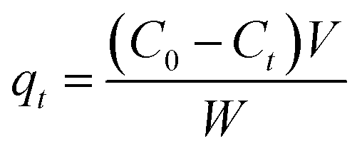
MIL-100(Fe) was synthesized according to the literature.24 The resulting MIL-100(Fe) was calcined from 293 K to 973 K under N2 atmosphere at a heating rate of 5 K min−1 in the tube furnace to synthesize MCPCs (see Fig. 1). After cooling down, the MCPCs was treated with ethanol and ultrapure water, respectively, then placed in vacuum and dried at 393 K for 12 h before use.
 |
| | Fig. 1 Synthesis of MCPCs from MIL-100(Fe) and adsorption. | |
Adsorption experiments
The MG samples were prepared in water. The as-prepared MCPCs were used as an adsorbent for adsorption of MG. The batch experiments were operated in a 10 mL vial. The MCPCs (10.0 ± 0.2 mg) was dispersed in MG solution (5 mL of each with the concentration of 25–300 mg L−1) under ultrasonication for 10 s, and then performed in an incubator shaker. The MG solution was pre-adjusted to pH (3–9) with NaOH (1.0 M) and HCl (1.0 M). The adsorption was conducted at 303 K in the dark, and the supernatant was conveniently separated using a permanent magnet at irregular time intervals for a kinetic study. In order to investigate thermodynamic equilibrium at different temperatures (298–323 K), the adsorption of MG was kept via a static method for 60 h. Control experiments were performed under the same conditions without the addition of MCPCs. All batch experiments were performed in triplicate. Two pond water samples were collected from Jiayuguan (Plot 1) and Lanzhou (Plot 2) during May in 2018 in Gansu province (Fig. S1†), and used for removal effect and feasibility of proposed method. All the samples were separated using a permanent magnet immediately and the absorbance of MG in the supernatant was analyzed by means of UV spectrophotometer (λmax = 617 nm).
Desorption and regeneration
To explore the regeneration of the MCPMs, desorption experiments were carried out. The MG-loaded MCPMs (10.0 mg) were eluted with different organic solvents such as acetone, ethanol and acetonitrile under ultrasonication conditions for 60 min and 5 mL solvent were used twice for the regeneration of the adsorbent.
Results and discussion
Characterization of MIL-100(Fe) and MCPCs
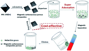
The synthesized MIL-100(Fe) and MCPCs were characterized by SEM, N2 adsorption–desorption, XRD, and TGA. The morphology of iron-based MOF MIL-100(Fe) (Fig. 2A) and annealed magnetic MCPCs (Fig. 2B) were characterized by SEM. The size of MCPCs is larger than iron-based MIL-100(Fe) nanocrystals, indicating the structure of MIL-100(Fe) nanocrystals was destroyed and recrystallized during pyrolysis process. Meanwhile, the high-resolution transmission electron microscopy (HRTEM) images further confirmed the formation of MCPMs particles and showed the microstructure of MCPMs particles. In Fig. 2C, MCPMs particles appeared a wide size distribution with Fe3O4 embedded in distinct carbon layer of light field contrast, suggesting that carbon layer was produced by destroying the organic links from previous frameworks. Meanwhile, iron cluster was oxidized during pyrolysis processes, which contribute to magnetic property of the MCPMs. From Fig. 2D, it can be inferred that the Fe3O4 nanoparticle was structurally uniform with a lattice fringe, which was further confirmed by the results of XRD pattern (Fig. 3A). We can infer from the TG curve that the MIL-100(Fe) framework should be decomposed over 873 K (Fig. 3B). The MCPMs presented a BET surface area of 706 m2 g−1. The Barrett–Joyner–Halenda (BJH) method was employed to estimate the pore size distribution of the MCPCs. As indicated in Fig. 3D, both of micropores and mesopores were existed in the MCPCs. A typical hysteresis loop in the isotherm gave further evidence of the composite with meso-scaled pores (Fig. 3C). As shown in Fig. 3E, the field-dependent magnetization loop of magnetic MIL-100(Fe) composites was measured over the range from −80 to 80 KOe. There were no apparent hysteresis, coercivity and remanence in the saturation magnetization curve. The MCPCs gave 19.8 emu g−1 saturation magnetization value, which is suitable for magnetic separation.
 |
| | Fig. 2 SEM images of MIL-100(Fe) (A) and MCPCs (B); HRTEM image of MCPCs (C and D). | |
 |
| | Fig. 3 (A) PXRD pattern of Fe3O4, as-synthesized MIL-100(Fe) and MCPCs; (B) TG curve of as-synthesized MOF MIL-100(Fe); (C) N2 adsorption–desorption isotherm and (D) pore size distribution of MCPCs (inset); (E) Magnetization curve of MCPCs (blue line) and Fe3O4 (black line). | |
Effect of pH
To evaluate the ionization degree of MG and stability of the MCPCs in solution, pH of MG solution were varied from 3 to 9. The influence of pH on the adsorption efficiency of MG on MCPCs was presented in Fig. 4. The adsorption capacity increased as the pH increased. This result can be ascribed to serious iron leaching when pH below 4. Meanwhile, the –N(CH3)2 in MG is protonated in acidic medium (pKa = 10.3).25 At higher pH, the association of MG cations with the more negative charged sites of the MCPCs could easily take place thereby increasing MG removal. Therefore, the pH value of 8 was optimal for the adsorption.
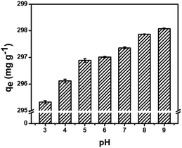 |
| | Fig. 4 Influence of pH on the adsorption of MG on MCPCs. | |
Effect of ionic strength
The dye wastewater contains various salts and metal ions, which could affect the adsorption efficiency of adsorbents. It can be observed in Fig. 5 that the adsorption capacity of MG on the MCPCs was significantly affected by the salt concentration. The adsorbed capacity decreased unexpectedly when the NaCl concentration was 0.02 mol L−1. However, while increasing the salt concentration to 0.10 mol L−1, such negative influence would become negligible. As described, the electrostatic interaction may play the key role in the adsorption process.
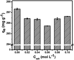 |
| | Fig. 5 Effect of ionic strength. | |
Adsorption isotherms study. Two adsorption isotherm models, Freundlich model and Langmuir model, were explored to investigate the interaction between the MCPCs and MG. The adsorption capacity at equilibrium and time t, are qe (mg g−1) and qt (mg g−1), respectively, which was calculated using eqn (1) and (2):| |
 | (1) |
| |
 | (2) |
Langmuir isotherm equation was expressed by the following equation (eqn (3)):
| |
 | (3) |
where
qe (mg g
−1) is the mass of MG dye uptake per unit weight of adsorbent (MCPCs) at equilibrium. The concentration of unadsorbed adsorbate (MG) is
C0 (mg L
−1) at initial, as well as
Ce (mg L
−1) at equilibrium in aqueous solution.
V (L) is the volume of the dye solution and
W (g) is the mass of magnetic sorbent. The constant
Q is the monolayer adsorption capacity, and
KL (L mg
−1) is the adsorption energy parameter of the Langmuir's equation. Both of
Q and
KL could be easily calculated from the slope and intercept, respectively.
Generally, Freundlich isotherm model was succeed in describing undesirable adsorption on rough surfaces due to the presence of diverse adsorbed site with functional groups. The Freundlich equation is represented as eqn (4):
| |
 | (4) |
where the constants
KF (mg g
−1 (L mg
−1)
1/n) and 1/
n are important Freundlich's parameters. 1/
n (unitless) depends on the linearity and varies between 0 and 1, implying adsorption intensity.
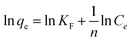
As shown in Fig. 5A, the adsorption isotherms were tested for MG on MCPCs at four different temperatures (298, 303, 313 and 323 K). We can see that the unit equilibrium adsorption amount of MCPCs to MG solution increased with increasing concentration of MG at the same temperature. Besides, as temperature increased, adsorption ability of MCPCs has improved, bringing a corresponding increase in KF value. The adsorption of MG is endothermic process. The maximum Langmuir adsorption capacities of MG on MCPCs at 298, 303, 313 and 323 K are 1170, 1454, 1752, 2090 mg g−1, respectively. The adsorption capacity of MG on MCPCs is much higher than many other reported adsorbents,18,20,22,26–30 (Table 1). It is worth noting that the adsorption isotherms in the Fig. 6A are not saturated, also suggesting the super high adsorption capacity of MCPCs for MG.
Table 1 Comparison of magnetic porous carbon material with other adsorbents for the adsorption of MG
| Adsorbents |
Dosage of adsorbent (mg) |
Sample volume (mL) |
Matched adsorption isotherm model |
Kinetic model |
Maximum adsorption capacity (Qmax, mg g−1) |
Ref. |
| MOF-2 |
10 |
5 |
Langmuir, D-R, Freundlich |
Pseudo-first-order |
185.4 |
26 |
| MIL-101-SO3H |
50 |
50 |
Langmuir |
Pseudo-second-order |
596 |
27 |
| NH2-MIL-101(Al) |
10 |
5 |
Langmuir |
Pseudo-second-order |
274 |
28 |
| MIL-53(Al)–NH2 |
10 |
100 |
Langmuir Freundlich |
Pseudo-second-order |
141 |
29 |
| MIL-100(Fe) |
10 |
5 |
Freundlich |
Pseudo-second-order |
485 |
20 |
| Banboo-based activated carbon |
200 |
200 |
Langmuir |
Pseudo-second-order |
264 |
30 |
| Ni/PC-CNT |
5 |
20 |
Langmuir Freundlich |
Pseudo-second-order |
898 |
22 |
| Dodecyl sulphate functionalized magnetic graphene oxide |
15 |
25 |
Langmuir |
Pseudo-second-order |
714 |
18 |
| Magnetic biochar |
25 |
50 |
Langmuir |
Pseudo-second-order |
388.68 |
31 |
| Coal fly ash/CoFe2O4 composites |
600 |
150 |
Freundlich, Dubinin–Kaganer–Radushkevich |
— |
89.3 |
32 |
| Citrate stabilized iron oxide nanoparticles |
50 |
5 |
Freundlich |
Pseudo-second-order |
490 |
33 |
| γ-Fe2O3/C |
10 |
5 |
Langmuir |
Pseudo-second-order |
499 (303 K),863 (333 K) |
34 |
| Superparamagnetic nanoadsorbent |
20 |
10 |
Langmuir |
— |
18.52 |
35 |
| Magnetic porous carbon material |
10 |
5 |
Langmuir, Freundlich |
Pseudo-second-order |
1170–2090 |
This work |
 |
| | Fig. 6 Adsorption isotherms of MG on MCPCs at various temperatures (A) and Freundlich model Plots of ln![[thin space (1/6-em)]](https://www.rsc.org/images/entities/char_2009.gif) Ce lnqe vs. lnCe at different temperatures (B). Ce lnqe vs. lnCe at different temperatures (B). | |
All the experimental adsorption isomers were fitted well with the Langmuir and the Freundlich equation. KF and 1/n, listed in Table 2, were obtained by Freundlich model plots of lnqe vs. lnCe at four temperatures (Fig. 6B). The values of 1/n were calculated over a range of 0.154–0.321, which suggests that it is favorable for the adsorption process, and the MCPCs possesses heterogeneous surface produced during the pyrolysis process. Multi-layer adsorption might exist due to apparent lack of plateau in adsorption isotherms, indicating that the MCPCs possess superior adsorption capacity.
Table 2 Characteristic parameters of isotherm equations for adsorption of MG on MCPCsa
| T (K) |
Langmuir parameter |
Freundlich parameter |
ΔG0 (kJ mol−1) |
ΔH0 (kJ mol−1) |
ΔS0 (J mol−1 K−1) |
| Q (mg g−1) |
KL (L mg−1) |
R2 |
1/n |
KF |
R2 |
| K0 (L g−1) is the equilibrium constant, obtained from eqn (5). Cs and Ce (mg g−1) are the adsorbed and equilibrium concentration of adsorbate (MG), respectively. T (K) is temperature, and R (8.031, J K−1 mol−1) is universal gas constant. |
| 298 |
1170 |
0.0176 |
0.990 |
0.154 |
390 |
0.990 |
−11.7 |
29.7 |
140 |
| 303 |
1454 |
0.0151 |
0.989 |
0.222 |
318 |
0.990 |
−13.0 |
| 313 |
1752 |
0.0252 |
0.991 |
0.250 |
369 |
0.993 |
−14.4 |
| 323 |
2090 |
0.0509 |
0.992 |
0.321 |
395 |
0.990 |
−15.3 |
Thermodynamics and kinetics. To better understand the adsorption mechanism, adsorption data are utilized to obtain the thermodynamic parameters, such as the standard enthalpy change (ΔH0, kJ mol−1), the standard free Gibbs energy change (ΔG0, kJ mol−1) and the standard entropy change (ΔS0, J mol−1 K−1) in the adsorption were calculated as follow:| |
 | (5) |
| | |
ΔG0 = RTlnK0
| (6) |
| |
 | (7) |
The thermodynamic parameters of ΔH0 and ΔS0 were obtained by plotting lnK0 of the eqn (6) and (7) against 1/T. The determined values of lnK0, ΔG0, ΔH0 and ΔS0 are given in Table 1. Negative ΔG0 (−11.7 to −15.3 kJ mol−1) means spontaneous adsorption of MG on MCPCs. The endothermic process of adsorption of MG on MCPCs was confirmed by positive value of ΔH0 (29.7 kJ mol−1, Table 2), which is most probably due to chemisorption occurred between metal atoms (Fe) in defect structure of pore and N atoms in MG. Positive value of ΔS0 became favored for spontaneous adsorption of MG on MCPCs, due to increasing randomness at the interface between MCPCs and MG solution with an increase of freedom of adsorbed MG. Meanwhile, dehydration may occur at the solid–liquid interface during adsorption.
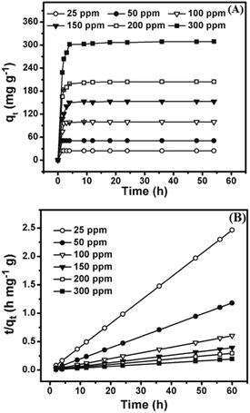
The adsorption kinetics were studied to elucidate the adsorption capacity and mechanism of MG on MCPCs. Fig. 7A revealed the adsorption capacity MG on MCPCs increased significantly in the beginning period, indicating the surface is large enough to favor high adsorption at initial high concentrations of MG and initial MG concentration could penetrate the resistance of dye transfer between MCPCs and MG by a strong driving force. The equilibrium time in MG adsorption was determined within 2.5 h, showing the fast adsorption kinetics of MCPCs for MG, which is quite important and economical to apply in wastewater treat plant. Pseudo-first-order and pseudo-second-order kinetic model were used to explore the adsorption kinetics of MG on MCPCs. A linear form of the pseudo-first-order kinetics model is given as:
| | |
ln(qe − qt) = lnqe − k1t
| (8) |
where
qt (mg g
−1) is the adsorption capacities of MG adsorbed per unit mass of MCPCs at any time
t (min), as well as
qe (mg g
−1) is the adsorption capacities at equilibrium. While
k1 (min
−1) represents the rate constant, calculated from the plots of ln(
qe −
qt)
versus t in pseudo-first-order adsorption model.
 |
| | Fig. 7 (A) Effect of contact time on the adsorption of MG on MCPCs (10 mg) at different initial concentrations of MG at 303 K and pH 8.0; (B) plots of pseudo-second-order kinetics for the adsorption of MG on MCPCs (10 mg). | |
The pseudo-second-order kinetics model is represented by the following equation: (eqn (9)):29
| |
 | (9) |
where
k2 is the rate constant of sorption (g mg
−1 min
−1),
qt and
qe are the adsorption capacity (mg g
−1) at any time
t (min) and at equilibrium, respectively. The plots of
t/
qt against
t showed straight lines relationship (
Fig. 7B),
k2 and
qe can be obviously calculated from the intercepts and slopes. The equilibrium adsorption performance was perfect because
qe varied from 24.8 to 299 mg g
−1 as starting MG concentration raised from 25.0 to 300 mg L
−1. In
Table 3, the values of
R2 for pseudo-second-order kinetic formula were preferred to that of pseudo-first-order kinetic formula. The values of
qe coincide with the pseudo-second-order model, showing the pseudo-second-order kinetic model is favorable to express the adsorption kinetics of MG on MCPCs.
Table 3 Kinetic parameters for the adsorption of MG on MCPCs at 298 Ka
| C0 |
qe(exp) (mg g−1) |
Pseudo-first-order kinetic model |
Pseudo-second-order kinetic model |
| qe(cal) |
k1 |
R2 |
qe(cal) |
k2 |
R2 |
| C0, initial concentration of MG (mg L−1); qe(cal), calculated adsorption capacity (mg g−1); qe(exp), experimental adsorption capacity (mg g−1); k1, k2, pseudo-second-order kinetic constant (g mg−1 min−1). |
| 24.46 |
24.4 |
0.13 |
9.9 × 10⁻³ |
0.577 |
24.3 |
0.025 |
0.999 |
| 51.00 |
50.9 |
0.66 |
3.5 × 10⁻³ |
0.354 |
50.8 |
0.038 |
0.999 |
| 99.68 |
99.6 |
3.91 |
4.5 × 10⁻² |
0.325 |
99.6 |
0.033 |
0.999 |
| 167.0 |
166.8 |
39.0 |
5.7 × 10⁻² |
0.771 |
153.6 |
0.035 |
1 |
| 204.6 |
204.5 |
50.6 |
7.5 × 10⁻² |
0.726 |
204.9 |
0.036 |
1 |
| 309.4 |
309.2 |
188.7 |
9.3 × 10⁻² |
0.928 |
310.5 |
0.014 |
0.999 |
Recovery and reuse of MCPCs. Recovery and reuse of the adsorbent are key factors to be considered during the practical applications. Hence, we investigate the recovery and reusability of the MCPCs. The MCPCs was easily separated from aqueous solutions by an external magnet (Fig. 8A and B). The MG-loaded MCPCs were regenerated by using acetonitrile, ethanol, and acetone as eluent assisted with ultrasound. The desorption efficiency of acetonitrile is superior to those of ethanol and acetone, with desorption efficiency of 90.2%, 35.7% and 71.3%, respectively (see Fig. 8C). The adsorbent is stable after desorption and regeneration. Furthermore, there is no apparent adsorption efficiency loss after six cycles (Fig. 8D). The rapid adsorption, large adsorption capacity and the good reusability of MCPCs for MG encouraged us to investigate its practicle use. MCPCs was dispersed in the pond wastewater containing spiked MG (25 mg L−1). A clear supernatant was obtained after rapid adsorption and separation of MCPCs with the external magnet (Fig. 8A and B). The results suggested that MCPCs is a cost effective and high performance adsorbent for MG adsorption and removal from wastewater.
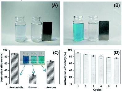 |
| | Fig. 8 Photographs for adsorption performance of MCPCs on MG in unspiked (A) and spiked (B) MG wastewater; Effect of desorption solution (C) and re-usability of MCPCs (D). | |
Conclusions
In summary, MCPCs was synthesized via pyrolysis of MIL-100(Fe) and employed as an efficient and recyclable adsorbent to remove MG from water. The adsorption kinetics conformed to a pseudo-second order model. Thermodynamic analysis of ΔG0, ΔH0 and ΔS0 indicated that the adsorption was spontaneous, endothermic and favorable. The adsorption proceeded rapidly and exhibited large adsorption capacity (up to 2090 mg g−1 for MG) and excellent reusability, which make it attractive for practical removal of MG from aqueous solutions.
Conflicts of interest
There are no conflicts of interest to declare.
Acknowledgements
We specially acknowledge the financial support from the National Natural Science Foundation of China (No. 21305112, 21462036).
References
- P. P. Sun, L. Xu, J. Li, P. Y. Zhai, H. Zhang, Z. S. Zhang and W. C. Zhu, Chem. Eng. J., 2018, 334, 377–388 CrossRef CAS.
- J. X. Dong, C. Xu, H. Wang, Z. L. Xiao, S. J. Gee, Z. F. Li, F. Wang, W. J. Wu, Y. D. Shen, J. Y. Yang, Y. M. Sun and B. D. Hammock, J. Agric. Food Chem., 2014, 62, 8752–8758 CrossRef CAS PubMed.
- Y. C. Lee, E. J. Kim, J. W. Yang and H. J. Shin, J. Hazard. Mater., 2011, 192, 62–70 CAS.
- P. Himanshu, Sep. Sci. Technol., 2018, 53, 2797–2812 CrossRef.
- Z. Q. Cai, Y. M. Sun, W. Liu, F. Pan, P. Z. Sun and J. Fu, Environ. Sci. Pollut. Res., 2017, 24, 15882–15904 CrossRef CAS PubMed.
- N. Daneshvar, A. R. Khataee, M. H. Rasoulifard and M. Pourhassan, J. Hazard. Mater., 2007, 143, 214–219 CrossRef CAS PubMed.
- J. X. Fan, D. Y. Chen, N. J. Li, Q. F. Xu, H. Li, J. H. He and J. M. Lu, Chemosphere, 2018, 191, 315–323 CrossRef CAS PubMed.
- L. Zhang, X. Y. Liu, X. J. Guo, M. M. Su, T. C. Xu and X. Y. Song, Chem. Eng. J., 2011, 173, 737–742 CrossRef CAS.
- B. Ghorani, N. Tucker and M. Yoshikawa, Food Res. Int., 2015, 78, 448–464 CrossRef CAS PubMed.
- R. P. Han, Y. Wang, Q. Sun, L. L. Wang, J. Y. Song, X. T. He and C. C. Dou, J. Hazard. Mater., 2010, 175, 1056–1061 CrossRef CAS PubMed.
- K. Tewari, G. Singhal and R. K. Arya, Rev. Chem. Eng., 2018, 34, 427–453 CAS.
- Y. Önal, C. Akmil-Başar and Ç. Sarıcı-Özdemir, J. Hazard. Mater., 2007, 146, 194–203 CrossRef PubMed.
- F. Nasiri Azad, M. Ghaedi, K. Dashtian, S. Hajati, A. Goudarzi and M. Jamshidi, New J. Chem., 2015, 39, 7998–8005 RSC.
- M. Rajabi, B. Mirza, K. Mahanpoor, M. Mirjalili, F. Najafi, O. Moradi, H. Sadegh, R. Shahryari-ghoshekandi, M. Asif, I. Tyagi, S. Agarwal and V. K. Gupta, J. Ind. Eng. Chem., 2016, 34, 130–138 CrossRef CAS.
- B. H. Beakou, K. El Hassani, M. A. Houssaini, M. Belbahloul, E. Oukani and A. Anouar, Water Sci. Technol., 2017, 76, 1447–1456 CrossRef CAS PubMed.
- G. Z. Kyzas, E. A. Deliyanni, D. N. Bikiaris and A. C. Mitropoulos, Chem. Eng. Res. Des., 2018, 129, 75–88 CrossRef CAS.
- S. Q. Zhao, D. Chen, F. H. Wei, N. N. Chen, Z. Liang and Y. Luo, J. Chem. Technol. Biotechnol., 2018, 93, 698–709 CrossRef CAS.
- A. A. Yakout and M. A. Shaker, J. Taiwan Inst. Chem. Eng., 2016, 63, 81–88 CrossRef CAS.
- W. H. Huang, J. Z. Li, T. Liu, L. S. Gao, M. Jiang, Y. N. Zhang and Y. Y. Wang, RSC Adv., 2015, 5, 97127–97132 RSC.
- S. H. Huo and X. P. Yan, J. Mater. Chem., 2012, 22, 7449–7455 RSC.
- J. Y. Park, D. W. Feng and H. C. Zhou, J. Am. Chem. Soc., 2015, 137, 11801–11809 CrossRef CAS PubMed.
- L. Jin, X. Zhao, X. Qian and M. Dong, J. Colloid Interface Sci., 2018, 509, 245–253 CrossRef CAS PubMed.
- Y. Hwang, D. Hong, J. Chang, S. Jhung, Y. Seo, J. Kim, A. Vimont, M. Daturi, C. Serre and G. Ferey, Angew. Chem., Int. Ed., 2008, 47, 4144–4148 CrossRef CAS PubMed.
- S. H. Huo, H. Y. An, J. Yu, X. F. Mao, Z. Zhang, L. Bai, Y. F. Huang and P. X. Zhou, J. Chromatogr. A, 2017, 1517, 18–25 CrossRef CAS PubMed.
- Y. C. Lee, J. Y. Kim and H. J. Shin, Sep. Sci. Technol., 2013, 48, 1093–1101 CrossRef CAS.
- Z. N. Shi, L. Li, Y. X. Xiao, Y. X. Wang, K. K. Sun, H. X. Wang and L. Liu, RSC Adv., 2017, 7, 30904–30910 RSC.
- X. P. Luo, S. Y. Fu, Y. M. Du, J. Z. Guo and B. Li, Microporous Mesoporous Mater., 2017, 237, 268–274 CrossRef CAS.
- H. C. Liu, L. G. Chen and J. Ding, RSC Adv., 2016, 6, 48884–48895 RSC.
- C. Li, Z. Xiong, J. Zhang and C. Wu, J. Chem. Eng. Data, 2015, 60, 3414–3422 CrossRef CAS.
- B. H. Hameed and M. I. J. El-Khaiary, J. Hazard. Mater., 2008, 157, 344–351 CrossRef CAS PubMed.
- J. Zhang, M. Liu, T. Yang, K. Yang and H. Wang, Water Sci. Technol., 2016, 74, 1971–1979 CrossRef CAS PubMed.
- M. Zhang, Y. Mao, W. Wang, S. Yang, Z. Song and X. Zhao, RSC Adv., 2016, 6, 93564–93574 RSC.
- R. R. Mishra, P. Chandran and S. S. Khan, RSC Adv., 2014, 4, 51787–51793 RSC.
- C. Zhang, F. Ye, S. Shen, Y. Xiong, L. Su and S. Zhao, RSC Adv., 2015, 5, 8228–8235 RSC.
- M. Yadav, M. Das, C. Savani, S. Thakore and R. Jadeja, ACS Omega, 2019, 4, 11993–12003 CrossRef CAS.
Footnote |
| † Electronic supplementary information (ESI) available. See DOI: 10.1039/c9ra04310a |
|
| This journal is © The Royal Society of Chemistry 2019 |
Click here to see how this site uses Cookies. View our privacy policy here. 
 Open Access Article
 This Open Access Article is licensed under a Creative Commons Attribution-Non Commercial 3.0 Unported Licence
 *ab,
Chen-Xu Liua,
Peng-Xin Zhou*a,
Jing Yua,
Lei Baiab,
Zhen-Gang Hanab and
Xiao-Quan Lu
*ab,
Chen-Xu Liua,
Peng-Xin Zhou*a,
Jing Yua,
Lei Baiab,
Zhen-Gang Hanab and
Xiao-Quan Lu