 Open Access Article
Guided cellular orientation concurrently with cell density gradient on butterfly wings†
Jie Lu a,
Ye Pan*a,
Qifeng Zhongb and
Bing Liuc
aSchool of Materials Science and Engineering, Jiangsu Key Laboratory for Advanced Metallic Materials, Southeast University, Nanjing 211189, China. E-mail: panye@seu.edu.cn
bDepartment of Pharmaceutical Equipment and Electronic Instruments, School of Engineering, China Pharmaceutical University, Nanjing 210009, China
cState Key Laboratory of Bioelectronics, School of Biological Science and Medical Engineering, Southeast University, Nanjing 210096, China
First published on 19th August 2019
Abstract
A simple method to create guided cellular orientation is illustrated by assembling fibroblasts on the dorsal side of M. menelaus wings. Moreover, by inserting the wing into tendon fibroblasts suspension at a tilt angle, guided cellular orientation concurrently with the cell density gradient is formed on the butterfly wings.
In normal in vivo microenvironments, cellular organization, including cellular orientation and cell density, can induce different extracellular matrix components, which in turn lead to different cell growth, proliferation and apoptosis.1 By introducing different cell culture materials, such as substrates patterned with grooves or ridges, cell alignment could be induced effectively.2 Moreover, by employing mechanical loading,3 inkjet printing,4 chemical modification5 and other means,6 spatial variations in the cell density gradient can also be generated in many ways.7 However, some technologies tend to suffer certain drawbacks, such as low time efficiency and even decrease in cell viability during manipulation.8 Moreover, it is still difficult to obtain guided cellular orientation concurrently with a cell density gradient, which is a major concern in the recreation of many types of tissue junctions.
It has been suggested that many photonic architectures occur naturally in certain insects, such as butterfly wings.9 Morpho butterflies have impressed many researchers due to the amazing natural colours on their wings.10 It was found that the brilliant coloration originates from complex nanostructures located on the surface of a Morpho butterfly wings.11 Those periodic nano-ridge structures can control the propagation of photons, thus presenting butterflies with a brilliant structural color.12 Benefitted from the development of nanotechnology and materials science, many researches have fabricated different artificial wing-like photonic structures to duplicate the complex shape of the nanostructure of butterflies.13 However, they are fairly expensive, time consuming and could not meet the requirements of mass production.14 Considering this, the natural structures from Morpho butterflies has become an optimal choice for many researches. For example, Morpho butterfly wings have been used directly as vapour sensor and also in surface-enhanced Raman spectroscopy for many years.15
Herein, we propose a simple, inexpensive and reproducible method to create guided cellular orientation concurrently with a cell density gradient by assembling fibroblasts on butterfly wings. We found that the parallel periodic nanoridges on the butterfly wings could induce oriented alignment of cells. This is demonstrated by both NIH-3T3 fibroblasts and tendon fibroblasts. Moreover, by tilting the butterfly wings into a homogeneous tendon fibroblast suspension, the number of sedimentary cells above the wings alters accordingly, leading to naturally increasing cell density from one side of the butterfly wing to the other. Thus, the cell density gradient can be easily produced without any chemical modification or mechanical process. It is noteworthy to mention that the tendon fibroblasts with a gradient density still exhibited guided orientation after sedimentation. Therefore, both guided cellular orientation and gradient cell density assembled simultaneously in a convenient way. This simple and robust method will have potential applications in tissue engineering.
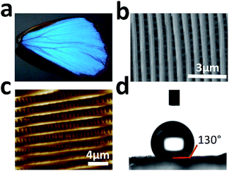
The wings of Morpho menelaus (M. menelaus) were selected as substrates for cell culture (Fig. 1a). First, scanning electron microscopy (SEM) was performed to investigate the micro/nanostructure of the wing. Fig. 1b illustrates the view of the ground scale of the composition of periodic parallel ridges. This anisotropic structure is the foundation of the structural colour of the M. menelaus wings. Atomic force microscopy (AFM) observations also show the same result for the micro/nanostructure on the wing (Fig. 1c). Normally, the original M. menelaus wings are strongly hydrophobic to protect the butterfly from rain and other natural disasters (Fig. 1d). However, this character might not be appropriate for direct applications in cell culture. Therefore, to improve the capacity for cell culture, the surface of M. menelaus wings should be treated prior to the cell experiment.
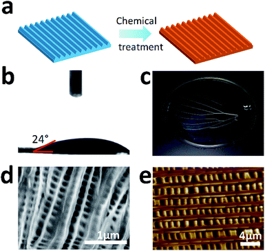
For the case study, the M. menelaus wing was pre-treated to become more biocompatible for use in cell culture (Fig. 2a). First, the wing was treated by oxygen plasma to generate hydroxyl, achieving a more hydrophilic surface (Fig. 2b). Inorganic salts were then removed from the wing using hydrochloric acid solution, followed by the removal of pigments and other proteins using sodium hydroxide solution. The wing turned transparent after the chemical treatments, indicating that the pigments and other proteins were removed (Fig. 2c). Here, the treated wing retained the slight blue structural colour, suggesting that main structure may not be destroyed after the treatment. SEM as well as AFM results confirmed that the parallel nanostructure is retained in the wing despite a little deformation of the ridges (Fig. 2d and e).
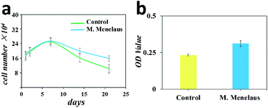
To investigate the biocompatibility, the treated M. menelaus wing was then prepared for cell culture. NIH-3T3 fibroblasts were chosen as their anisotropic behaviour would make results easy to observe. After a long culturing period, we found that the 3T3 fibroblasts assembled on the dorsal side of wing exhibited same proliferation tendency as those on the traditional culture dish (Fig. 3a). The number of these fibroblasts reached the peak amount within one week interval and gradually decreased in the following days, matching with the standard cell survival curve. Cell activity assay was also applied after 48 h culturing to evaluate the cell activities between the wing and cell culture plate. The results indicate that the 3T3 fibroblasts assembled on the treated wing demonstrate a slightly higher viability compared with the cells cultured on culture plate (Fig. 3b). Therefore, the treated M. menelaus wings possess excellent biocompatibility and are thus appropriate for cell adhesion and survival.
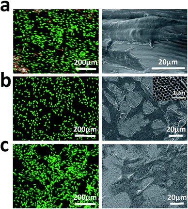
To check if the parallel periodic nanoridges on the dorsal side of the butterfly wings affect cell orientation, NIH-3T3 fibroblasts were cultured on the treated wing for a certain period. Since the M. menelaus wings are primarily made of chitin in most cases, a cell culturing system on a chitinous hybrid inverse opal substrate, on which the parallel strips were absent, was investigated for comparison. Meanwhile, cells cultured on the cell culture plate were also analyzed as a control. By taking the advantage of Calcein AM staining, it was found that the orientation of the cells on the parallel stripes of the butterfly wing became uniformly aligned (Fig. 4a), while cells on the culture plate and chitinous-modified substrate without parallel strips had disordered microfilaments (Fig. 4b and c). This was further confirmed by the corresponding SEM results. The fibroblasts exhibited induced orientation with distinct cell bipolarizations along the parallel stripes of the wing. In contrast, the fibroblasts on the culture plate as well as chitinous hybrid substrate patterned without parallel strips exhibited random orientation. The main possibility is that the stripes from the M. menelaus wing could induce cell arrangement by contact guidance. In addition, it was found that the guided cell orientation could also be achieved by using the inverse opal substrate, on which the surface was structured with stripe-like pattern (Fig. S1†). However, the parallel stripe structures located on the inverse opal substrate may suffer from batch-to-batch variations, thus affecting the cell performance.
To further confirm the trend of cell orientation, the angles between the growth direction of fibroblasts and the parallel stripes were measured and analyzed (Fig. 5). The results demonstrate that about 80% of NIH-3T3 fibroblasts exhibited an orientation within 30° of the stripes' direction. In contrast, no particular cell orientation was observed on the cell culture plate and chitinous hybrid substrate. Cell viabilities on those substrates were also investigated and no significant difference in cell viabilities were detected. All these results when considered together indicate that the M. menelaus wings could provide an appropriate environment for induced cell culture.
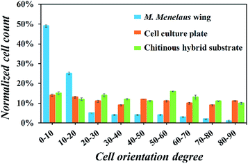 | ||
| Fig. 5 Orientation angle frequency distribution of NIH-3T3 fibroblasts on the butterfly wing, culture plate and hybrid substrate. | ||
Traditionally, cell density gradients are typically regulated by performing hemocytometer, which is time consuming and labour intensive.16 Alternatively, chemical and electrical means could be employed to establish cell density gradients.17 However, these methods are still plagued by poor reproducibility or low controllability. Recently, a simple method involving a glass substrate tilted in cell suspension for rapidly establishing cell density gradients was conducted.18 In this method, various cell gradient patterns could be assembled in a convenient way. Herein, we intend to gather cells with gradient density by utilizing the M. menelaus wings. To prevent floating above the cell suspension, the dorsal side of the clipped wing was attached to a polystyrene (PS) substrate. Having been used previously as the raw material for standard Petri dish and multi-well plates in cell culturing, PS was chosen as the supporting substrate since it has an adequate mechanical strength.19 Further, the wing-PS composite was then inserted into the cell suspension to gather the sediment cells.
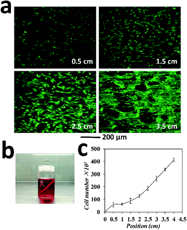
In this case study, tendon fibroblasts were chosen since they originated from connecting tissue, in which the gradient in cell types, organizations as well as extra cellular matrix represent a common feature. The wing-PS composite was then tilted at an angle of 45 degree and inserted into the tendon fibroblast suspension in such way that one end of the wing stripes were against the bottom of the cell culture container. The tilting angle of 45 degree was chosen since a clear observation of cell density gradient could be achieved at this angle as compared with the others (Fig. 6a). Cell sedimentation experiments with different tilting angles were also performed and the results are shown in Fig. S2.† The homogeneous suspension of tendon fibroblasts was set at a concentration of 3 × 10⁵ mL−1 in order to obtain a clear observation of cell density distribution after fluorescence staining. After 2 hours of setting, cell suspension became clear, indicating that most cells adhered on either the wing or at the bottom of the culture container. Following 24 h culturing time, the wing-PS composite was then extracted and rinsed briefly with a culture medium to wash away the unattached cells.
Normally, the clipped wings of M. menelaus are around 4 cm in length. The highest point on the wing is denoted as the starting point and the lowest point is denoted as the position of 4 cm. The total volume of the fibroblast suspension was set to barely immerse the starting point of the wing (Fig. 6b). Therefore, gradient patterns started from a density of zero at the starting point (that is there were no cells at this position available for sedimentation). Fluorescence staining was performed subsequently to help visualize the cells and determine whether the sedimentation process has influenced the cell viability. The cells at the position of 0.5 cm, 1.5 cm, 2.5 cm and 3.5 cm were examined (Fig. 6a). As expected, a clear gradient of cell density can be observed on the wing. Upon calculating, the number of fibroblasts adhered at the position of 0.5 cm was 6 × 10³, followed by 9 × 10³ at 1.5 cm, 19 × 103 at 2.5 cm and 34 × 103 at 3.5 cm. The highest number of cells was around 40 × 103 at the position of 4 cm. Thus, a clear gradient pattern of cell density is formed (Fig. 6c). Moreover, cells retained good viabilities after sedimentation, showing the great advantage of this method over other gradient generation approaches. It is worth mentioning that owing to the parallel stripes on the M. menelaus wing, those fibroblasts maintained guided orientation along the parallel stripes of the wing. Thus, guided cellular orientation concurrently with cell density gradient was formed easily on the butterfly wings without any complex procedures.
Conclusions
In summary, a simple and unique approach for rapidly generating guided cellular orientation concurrently with cell density gradient has been demonstrated. In this method, cell culture substrates were derived directly from natural M. menelaus wings without any complicated fabricating process. Due to the parallel stripes located on the surface of the M. menelaus wings, NIH-3T3 fibroblasts and tendon fibroblasts could be assembled in guided cell orientation. Moreover, by inserting the wing into a tendon fibroblast suspension at a tilt angle of 45 degree, the number of sedimentary fibroblasts above the wing altered accordingly. Thus, cell density gradient could be easily produced. More importantly, owing to parallel stripes on the M. menelaus wing, the cells with gradient density maintained induced orientation after sedimentation. The whole operation did not require any mechanical stimulation and thus cell viability was retained to be in maximum. Therefore, we believe this simple and robust strategy will find promising applications in tissue engineering.Experimental section
Materials
Morpho menelaus (M. menelaus) butterflies were purchased from Dieyu Company (Shanghai, China). Hydrochloric acid, sodium hydroxide, PS, toluene solution and glutaraldehyde were purchased from Aladdin Reagent (Shanghai, China). NIH-3T3 fibroblasts were obtained from Chinese Academy of Sciences. The tendon fibroblasts were harvested from rat supraspinatus and infraspinatus tendon samples. Fetal bovine serum without mycoplasma, penicillin–streptomycin double antibiotics, DMEM medium and 0.25% trypsin-EDTA were purchased from Gibco, USA. Calcein AM was purchased from Molecular Probes, USA. 3-(4,5-dimethyl-2-thiazolyl)-2,5-diphenyl-2-H-tetrazolium bromide (MTT) was obtained from J&K Scientic Ltd., Shanghai, China. Dimethyl sulfoxide (DMSO), chitin and collagen were obtained from Sigma, USA.Treatment of butterfly wings
Both ventral and dorsal sides of the wings were treated by oxygen plasma to change their surface wettability from super hydrophobic to hydrophilic (DT-01; SZ-Omega Ltd., China). To remove pigments, the wings were soaked in 1 M Hydrochloric acid for 2 h at room temperature. After rinsing with double-distilled water, the wings were soaked in 2 M sodium hydroxide for 30 min and then heated to 80 °C for 6 h. Finally, the wings were rinsed with double-distilled water to wash away the remaining sodium hydroxide. For cell culture, all M. menelaus wings were firstly clipped into stripe-type along the side of scaffolds. For cell density gradient study, the ventral sides of the stripe-type wings were then attached to the 20% PS-toluene solution. After the solidification of the solution, the wing-PS composites were ready for cell experiments.Preparation of hybrid substrate
An opal film template composed of monodisperse silica spheres was deposited on a glass by vertical deposition. 20% PS–toluene solution was then infiltrated into the voids of the opal template. After solidification of the solution, the silica spheres were etched with 4% hydrofluoric acid and washed with demi-water to form a free-standing inverse opal film. For stripe-like pattern, the film was uniaxially stretched by using a vernier caliper at 80 °C. Meanwhile, to prepare the hybrid inverse opal substrate, the inverse opal film was firstly immersed in the 0.5 wt% collagen solution containing chitin for one day at frozen condition. Subsequently, the film was further cross-linked by UV-irradiation for 1 min and then immersed into buffer solution. Due to different porosities in and out of the inverse opal, the gel in and out of the pore underwent a rupture. Finally, we obtained the hybrid inverse opal-hydrogel composites just after the film stripped from the less swelled hydrogel inside the pore.Cell culture, activity assay and image
NIH-3T3 fibroblasts and tendon fibroblasts were maintained separately in DMEM supplemented with 10% fetal bovine serum and 1% penicillin-streptomycin separately. All cells were placed in the incubator (HERA cell 150, Thermo, USA) at 37 °C and 5% CO2 and culture medium was changed every other day.In MTT cell activity assay, we firstly clipped the M. menelaus wings into small pieces. Moreover, the same sized glass slides were set as the control group. The sterile wings and glass slides were placed in a 24-well plate separately. The number of cells in each well was 2 × 10⁴. After 24 h incubation, wings and glass slides were transferred to a new 24-well plate separately. MTT solution was prepared by dissolving 0.5 g MTT in 100 mL PBS. 40 mL MTT solution and 360 mL culture medium were then incubated with cells at 37 °C for 4 h. Subsequently, the liquid was removed and DMSO was added to dissolve the formazan crystal formed in cells for further OD value measurement (Synergy HTX, Biotek, USA).
NIH-3T3 fibroblasts were stained for the visualization alignment by using Calcein AM. Briefly, cells were firstly washed with PBS and incubated with 10 mM Calcein AM solution that diluted with DMSO at 37 °C for 15 minutes. Cells were then washed and stored with PBS for fluorescence microscope observation (OLYMPUS IX71, Olympus, Japan).
Characterization
To characterize the detail of cultured cells, the samples were immersed in 3% glutaraldehyde for 24 h and then washed by PBS solution repeatedly and was dehydrated with gradient ethanol (20%, 40%, 60%, 80%, and 100%). Further, samples were sputter-coated with gold before SEM viewing (S-3000N, Hitachi, Japan).Conflicts of interest
There are no conflicts to declare.Acknowledgements
This work was supported by Jiangsu Planned Projects for Postdoctoral Research Funds (2018K178C), the Fundamental Research Funds for the Central Universities (2242018R20015), China Postdoctoral Science Foundation funded project (2018M642132).References
- (a) S. N. Bhatia, U. J. Balis, M. L. Yarmush and M. Toner, FASEB J., 1999, 13, 1883–1900 CrossRef CAS PubMed; (b) G. Yang, Y. H. Cao, J. B. Fan, H. L. Liu, F. L. Zhang, P. C. Zhang, C. Huang, L. Jiang and S. T. Wang, Angew. Chem., 2014, 126, 2959–2962 CrossRef; (c) J. Lu, X. Zou, Z. Zhao, Z. Mu, Y. Zhao and Z. Gu, ACS Appl. Mater. Interfaces, 2015, 7, 10091–10095 CrossRef CAS.
- (a) S. Watari, K. Hayashi, J. A. Wood, P. Russell, P. F. Nealey, C. J. Murphy and D. C. Genetos, Biomaterials, 2012, 33, 128–136 CrossRef CAS PubMed; (b) A. S. Andersson, P. Olsson, U. Lidberg and D. Sutherland, Exp. Cell Res., 2003, 288, 177–188 CrossRef CAS PubMed.
- X. R. Li, J. W. Xie, J. Lipner, X. Y. Yuan, S. Thomopoulos and Y. N. Xia, Nano Lett., 2009, 9, 2763–2768 CrossRef CAS PubMed.
- J. A. Barron, P. Wu, H. D. Ladouceur and B. R. Ringeisen, Biomed. Microdevices, 2004, 6, 139–147 CrossRef CAS PubMed.
- S. Y. Cheng, S. Heilman, M. Wasserman, S. Archer, M. L. Shuler and M. M. Wu, Lab Chip, 2007, 7, 763–769 RSC.
- Y. Du, M. J. Hancock, J. He, J. L. Villa-Uribe, B. Wang, D. M. Cropek and A. Khademhosseini, Biomaterials, 2010, 31, 2686–2694 CrossRef CAS PubMed.
- T. Boland, T. Xu, B. Damon and X. Cui, Biotechnology Journal: Healthcare Nutrition Technology, 2006, 1, 910–917 CrossRef CAS PubMed.
- T. G. Ruardy, J. M. Schakenraad, H. C. Van der Mei and H. J. Busscher, J. Biomed. Mater. Res., 1995, 29, 1415–1423 CrossRef CAS PubMed.
- (a) P. Vukusic and J. R. Sambles, Nature, 2003, 424, 852 CrossRef CAS PubMed; (b) L. Li, S. Kolle, J. C. Weaver, C. Ortiz, J. Aizenberg and M. Kolle, Nat. Commun., 2015, 6, 6322 CrossRef CAS PubMed; (c) J. W. Galusha, L. R. Richey, M. R. Jorgensen, J. S. Gardner and M. H. Bartl, J. Mater. Chem., 2010, 20, 1277–1284 RSC; (d) M. Srinivasara, Chem. Rev., 1999, 99, 1935–1962 CrossRef.
- (a) M. A. Giraldo, S. Yoshioka, C. Liu and D. G. Stavenga, J. Exp. Biol., 2016, 219, 3936–3944 CrossRef CAS PubMed; (b) W. Zhang, D. Zhang, T. Fan, J. Gu, J. Ding, H. Wang, Q. Guo and H. Ogawa, Chem. Mater., 2008, 21, 33–40 CrossRef.
- (a) S. Kinoshita, S. Yoshioka and K. Kawagoe, Proc. R. Soc. London, Ser. B, 2002, 269, 1417–1421 CrossRef PubMed; (b) L. P. Biro and J. P. Vigneron, Laser Photonics Rev., 2011, 5, 27–51 CrossRef; (c) G. L. Liao, H. B. Zuo, Y. B. Cao and T. L. Shi, Sci. China Ser. E Technol. Sci., 2010, 53, 175–181 CrossRef.
- Z. Chen, F. Fu, Y. Yu, H. Wang, Y. Shang and Y. Zhao, Adv. Mater., 2019, 31, 1805431 CrossRef PubMed.
- (a) R. A. Potyrailo, R. K. Bonam, J. G. Hartley, T. A. Starkey, P. Vukusic, M. Vasudev, T. Bunning, R. R. Naik, Z. Tang, M. A. Palacios, M. Larsen, L. A. Le Tarte, J. C. Grande, S. Zhong and T. Deng, Nat. Commun., 2015, 6, 7959 CrossRef PubMed; (b) R. A. Potyrailo, H. Ghiradella, A. Vertiatchikh, K. Dovidenko, J. R. Cournoyer and E. Olson, Nat. Photonics, 2007, 1, 123 CrossRef CAS; (c) K. Chung, S. Yu, C. J. Heo, J. W. Shim, S. M. Yang, M. G. Han, H. S. Lee, Y. Jin, S. Y. Lee, N. Park and J. H. Shin, Adv. Mater., 2012, 24, 2375–2379 CrossRef CAS PubMed; (d) B. Song, S. C. Eom and J. H. Shin, Opt. Express, 2014, 22, 19386–19400 CrossRef PubMed.
- A. R. Parker and H. E. Townley, Nat. Nanotechnol., 2007, 2, 347 CrossRef CAS PubMed.
- (a) C. A. Tippets, Y. L. Fu, A. M. Jackson, E. U. Donevet and R. Lopez, J. Opt., 2016, 18, 06510 CrossRef; (b) N. L. Garrett, R. Sekine, M. W. A. Dixon, L. Tilley, K. R. Bambery and B. R. Wood, Phys. Chem. Chem. Phys., 2015, 17, 21164–21168 RSC.
- J. Wu, Q. Chen, W. Liu and J. M. Lin, Lab Chip, 2013, 13, 1948–1954 RSC.
- (a) A. M. Wan, D. J. Brooks, A. Gumus, C. Fischbach and G. G. Malliaras, Chem. Commun., 2009, 5278–5280 RSC; (b) A. Gumus, J. P. Califano, A. M. Wan, J. Huynh, C. A. Reinhart-King and G. G. Malliaras, Soft Matter, 2010, 6, 5138–5142 RSC; (c) M. Bongo, O. Winther-Jensen, S. Himmelberger, X. Strakosas, M. Ramuz, A. Hama, E. Stavrinido, G. G. Malliara, A. Salleo, B. Winther-Jensen and R. M. Owens, J. Mater. Chem. B, 2013, 1, 3860–3867 RSC.
- W. Liu, Y. Zhang, S. Thomopoulos and Y. Xia, Angew. Chem., Int. Ed., 2013, 52, 429–432 CrossRef CAS PubMed.
- A. S. Curtis, J. V. Forrester, C. McInnes and F. Lawrie, J. Cell Biol., 1983, 97, 1500–1506 CrossRef CAS PubMed.
Footnote |
| † Electronic supplementary information (ESI) available. See DOI: 10.1039/c9ra03961a |
| This journal is © The Royal Society of Chemistry 2019 |

