
 Open Access Article
 This Open Access Article is licensed under a Creative Commons Attribution-Non Commercial 3.0 Unported Licence
A facile route to mechanically robust graphene oxide fibers†
Youbin
Kwon‡
,
Byoung-Sun
Lee‡
,
Sarang
Park
and
Woong-Ryeol
Yu
*
Department of Materials Science and Engineering, Research Institute of Advanced Materials (RIAM), Seoul National University, Seoul 08826, Republic of Korea. E-mail: woongryu@snu.ac.kr; Tel: +82-2-880-9096
First published on 28th June 2019
Abstract
Excellent mechanical, electrical, and thermal properties of graphene have been achieved at the macroscale by assembling individual graphene or graphene oxide (GO) particles. Wet-spinning is an efficient and well-established process that can provide GO assemblies in fiber form. The coagulation bath in the wet-spinning process has rarely been considered for the design of mechanically robust GO fibers (GOFs). In this study, locating the amidation reaction in the coagulation bath yielded mechanically improved GOFs. The imides 1-ethyl-3-(3-dimethylaminopropyl)carbodiimide and N-hydroxysuccinimide were used to form covalent amide bonds between GO flakes and chitosan, thereby reinforcing the GOFs. Evidence and effects of the amidation reaction were systematically examined. The tensile strength and breaking strain of the GOFs improved by 41.6% and 75.2%, respectively, and the toughness almost doubled because of the optimized crosslinking reaction. Our work demonstrated that using a coagulation bath is a facile way to enhance the mechanical properties of GOFs.
1. Introduction
Carbon fibers have extraordinary mechanical, thermal, and electrical properties that result from their turbostratic structure. They are used in many high-tech aerospace, automotive, and electrical applications.1 The superior material properties of single-crystalline graphite whiskers, e.g., high strength of 20 GPa and excellent electrical conductivity of 1.5 × 10⁶ S m−1,2 have stimulated the development of single-crystalline-like carbon fibers having properties exceeding those of conventional turbostratic carbon fibers. Graphene has emerged as a building block for this kind of carbon fiber due to its excellent material properties, such as high strength (130 GPa),3 Young's modulus (1 TPa),3 electrical conductivity (108 S m−1),4 and thermal conductivity (5000 W m K−1)5 at the nanoscale. Graphene oxide (GO), which is prepared by chemical oxidation and exfoliation of natural graphite, is of particular interest because it can be readily processed into macroscopic assemblies, such as GO fibers (GOFs). Such mass and solution processabilities are attributed to hydrophilic functional groups.6Graphene oxide has been used since 2011 to synthesize GO or reduced graphene fibers.7 Polymeric fibers are manufactured by aligning their constituent elements. To form GOFs, the GO units must first be aligned in solution, i.e., form a liquid crystalline phase. Fortunately, high-aspect-ratio particles can form nematic liquid crystalline phases above their critical concentrations.8,9 Graphene oxide particles can also be dispersed to form a nematic liquid crystalline phase; the high shear present in an extrusion orifice during wet-spinning aligns the nematic structure. Then, solvent exchange in a coagulation bath transforms the aligned GO structure into gel-fibers, which are converted into solid GOFs by subsequent drying. These GOFs have been intensively investigated for applications to conducting fibers,10,11 sensors,12–14 fiber supercapacitors,15–17 and batteries.18,19 Nevertheless, the mechanical properties of GO fibers are still inferior to those of the individual GO particle, and their improvement in this respect remains challenging.
Various approaches have been used to design mechanically robust GOFs. These include (i) mixing large and small GO flakes at the golden ratio,20 (ii) adding organic molecules in the spinning dope to form a composite fiber,21,22 and (iii) grafting polymer molecules on the GO surface.23 The coagulation bath is a suitable vessel via which to chemically treat GOFs, to modify their microstructure and thereby improve their mechanical properties. However, the coagulation bath has rarely been investigated in the context of the synthesis of mechanically robust GOFs. Herein, a coagulation solution (bath) was designed to enable crosslinking of the GO flakes within GOFs to improve the fiber mechanical properties. There have been many studies on high strength and modulus of GO fibers.20 In most studies however, improved mechanical properties of GO fibers were achieved using large sized GOs.24,25 In contrast, our study has been focused on the crosslinking reaction between GO and chitosan and its effect on the strength and modulus. We developed a new wet-spinning process with in situ crosslinking and characterized manufactured GO fibers using chemical and mechanical analyses to find optimum process condition. Since we have used small sized GOs, the mechanical properties of GO fibers in this study can be lower than other GO fibers based on large sized GOs. We expect that our finding on the optimum condition of the crosslinking between GOs and chitosan enables very strong and tough GOs to be manufactured if large sized GOs are used, which is beyond our research scope in this study.
Crosslinking between GO flakes occurs when carboxylic groups on the GO surface form amide groups by reacting with amine groups of chitosan during the amidation reaction in the coagulation bath. The amide group is a highly popular and reliable functional group because of its high polarity, stability, and conformational diversity.26 Herein, mechanically robust GOFs were synthesized via continuous wet-spinning followed by amidation in the coagulation bath. The effects of this process were systematically examined and the optimum reaction conditions were identified.
2. Experimental
2.1. Materials
An aqueous dispersion of GO flakes (V-50; 1 wt%; D < 10 µm, Fig. S1a†) was purchased from Standard Graphene Inc. Chitosan (medium molecular weight), 1-ethyl-3-(3-dimethylaminopropyl)carbodiimide (EDC), and N-hydroxysuccinimide (NHS) were supplied by Sigma-Aldrich. Acetic acid (99.7%) was purchased from Daejung Chemicals & Metals.2.2. Tough GO fiber synthesis
GOFs were manufactured by wet-spinning. First, the spinning dope was prepared using the GO dispersion. The concentrated GO dispersion was diluted to 0.5 wt% with distilled water and stirred for 24 h at room temperature. This solution was gently sonicated for 1 h in a bath-type sonicator and further filtered through a 400-mesh stainless steel sieve to remove agglomerates. The filtrate was then degassed in a vacuum chamber. The nematic liquid crystalline phase of the prepared spinning dope was confirmed using a polarized optical microscope (POM; BX-51; Olympus Co.) (Fig. S1b†). The schlieren texture, which is characteristic texture for nematic liquid crystal solution, evident in the POM image confirms the nematic phase.6,27 The liquid crystalline spinning dope was spun into a continuous fiber in a coagulation bath, in which the phase transition occurred by diffusion of the coagulant into the spinning dope; it is later solidified by evaporating the solvent.1,7 In this study, the aqueous coagulation solution was prepared by dissolving chitosan (3.0 g) in distilled water (500 mL) containing acetic acid (10 mL). The EDC (10 mM) and NHS (10 mM) were added to the coagulation solution to activate the reaction between the carboxylic acid groups of the GO surface and the amine groups of the chitosan molecules.Various GOFs were spun under different conditions using the prepared spinning dope and coagulation solution. A 27-gauge needle with an inner diameter of 0.2 mm was used as the wet-spinning nozzle; the feed rate of the spinning dope was 2 mL h−1. The wet-spun GO-gel fibers were collected at 50 cm min−1. Five groups of GO-gel fibers (denoted as C-GOF1, C-GOF2, C-GOF3, C-GOF4, and C-GOF5) were held in the coagulation bath for various periods (t = 1, 2, 3, 4, and 5 h, respectively) to examine the effect of crosslinking development on the mechanical properties of the produced GOFs. The C-GOFs were then rinsed with distilled water and placed between two stainless steel rods separated by 15 cm to solidify the gel fibers. The solidified fibers were further dried in a vacuum oven at 50 °C for 24 h. For reference, non-crosslinked GOFs were synthesized using the same processes, but without the chemical additives (EDC and NHS) and a further holding period in the coagulation bath.
2.3. Structural and mechanical characterizations
The GO and GOF morphologies were observed by field-emission scanning electron microscopy (FE-SEM; Supra 55VP; Carl Zeiss). Crosslinking between the GOFs and chitosan molecules was evaluated by Fourier transform-infrared spectroscopy (FT-IR; 4000–650 cm−1, resolution: 4 cm−1; Tensor 27; Bruker) and X-ray photoelectron spectroscopy (XPS; Sigma Probe; Thermo Fisher Scientific). Thermogravimetric analysis (TGA; TGA/DSC 1; Mettler Toledo) and differential scanning calorimetry (DSC; DSC 823e; Mettler Toledo) were used to examine the thermal decomposition behavior of the GOFs and the crosslinking reaction. The weight change of the GOFs was measured by TGA in the temperature range of 100 to 600 °C at a heating rate of 10 °C min−1 under an N2 atmosphere. Meanwhile, the heat flow for the thermal decomposition of the GOFs was measured by DSC in the temperature range of 25 to 320 °C at a heating rate of 10 °C min−1 under an N2 atmosphere. Before any DSC measurement, adsorbed water molecules were removed from the GOFs by heating to 150 °C, holding at this temperature for 5 min, and then cooling to room temperature. The heating and cooling were done at 10 °C min−1 in an N2 atmosphere.A swelling test was conducted to assess structural robustness. Samples of GOFs were soaked in distilled water (100 µL) and their diameter changes were monitored over time (0.5, 1, 3, 6, and 24 h) using an optical microscope. The mechanical properties of the GOFs were carefully examined using a single-fiber tensile test (gauge length: 10 mm, crosshead speed: 0.5 mm min−1) on a universal testing machine (UTM; RB 302 ML; R&B Co.).
3. Results and discussion
3.1. Chemistry and processing
The crosslinking amidation reaction between carboxyl groups and primary amine groups via the EDC/NHS activation mechanism28 was used to manufacture tough GOFs. Carboxyl-functionalized GO flakes were selected for the crosslinking reaction with the primary amine groups of chitosan molecules; the presence of carboxylate groups was confirmed by C![[double bond, length as m-dash]](https://www.rsc.org/images/entities/char_e001.gif) O absorption at about 1725 cm−1 in the FT-IR spectrum (Fig. S2a†).29 The amine groups were characterized by an N–H absorption at about 1560 cm−1 (Fig. S2a†).30 Fig. 1a schematically describes the crosslinking reaction. First, carboxylic acid groups on the GO flakes react with EDC to form unstable reactive O–acylisourea esters. These unstable EDC ester intermediates are stabilized by NHS addition to form NHS esters. Finally, the NHS ester intermediates react with the primary amine groups of the chitosan molecules to form stable amide crosslinks.31 Fig. 1b schematically illustrates the wet-spinning process. The chemical crosslinking reaction was designed to occur during gel-fiber formation in the coagulation bath. Pre-crosslinked solutions have been used to manufacture highly tough GO membranes.32 For the wet-spinning of GO fibers, liquid crystallinity of the spinning dope is very important, affecting the spinnability as well as the properties of spun fibers.33 When pre-crosslinking GO and chitosan is used for spinning dope, liquid crystalline phase of the spinning dope can be deteriorated by already-aggregated GO flakes. Thus, we believe that real-time (or in situ) crosslinking method is inevitable to maximizes the effect of the crosslinking in wet-spinning process. To confirm this, polarized optical microscope images of pre-crosslinked GO-chitosan aqueous solution were examined (Fig. S3†). In the pre-crosslinked GO-chitosan aqueous solution, schlieren texture, which is characteristic texture for nematic liquid crystal solution between crossed polarizers, could hardly be observed compared to GO aqueous solution and its spinnability was very limited.
O absorption at about 1725 cm−1 in the FT-IR spectrum (Fig. S2a†).29 The amine groups were characterized by an N–H absorption at about 1560 cm−1 (Fig. S2a†).30 Fig. 1a schematically describes the crosslinking reaction. First, carboxylic acid groups on the GO flakes react with EDC to form unstable reactive O–acylisourea esters. These unstable EDC ester intermediates are stabilized by NHS addition to form NHS esters. Finally, the NHS ester intermediates react with the primary amine groups of the chitosan molecules to form stable amide crosslinks.31 Fig. 1b schematically illustrates the wet-spinning process. The chemical crosslinking reaction was designed to occur during gel-fiber formation in the coagulation bath. Pre-crosslinked solutions have been used to manufacture highly tough GO membranes.32 For the wet-spinning of GO fibers, liquid crystallinity of the spinning dope is very important, affecting the spinnability as well as the properties of spun fibers.33 When pre-crosslinking GO and chitosan is used for spinning dope, liquid crystalline phase of the spinning dope can be deteriorated by already-aggregated GO flakes. Thus, we believe that real-time (or in situ) crosslinking method is inevitable to maximizes the effect of the crosslinking in wet-spinning process. To confirm this, polarized optical microscope images of pre-crosslinked GO-chitosan aqueous solution were examined (Fig. S3†). In the pre-crosslinked GO-chitosan aqueous solution, schlieren texture, which is characteristic texture for nematic liquid crystal solution between crossed polarizers, could hardly be observed compared to GO aqueous solution and its spinnability was very limited.
 | ||
| Fig. 1 Cross-sectional and surface field-emission scanning electron microscopy images of graphene oxide fibers (GOFs) and chemically crosslinked GOFs (C-GOFs). (a and b) GOFs, (c and d) C-GOF1, (e and f) C-GOF2, (g and h) C-GOF3, (i and j) C-GOF4, and (k and l) C-GOF5. Marked areas were used for the effective diameter calculation. | ||
3.2. Morphologies of the GOFs
The GOFs were successfully manufactured by the liquid crystal wet-spinning process, as shown by cross-sectional and surface SEM images (Fig. 2). Short residence times in the coagulation bath were expected to limit the extent of crosslinking of the chitosan. The effective diameter of the fibers can be confirmed by the area inside the outline of the cross-sectional SEM images; equivalent circular cross-sectional areas were assumed because of the non-cylindrical morphology of the GOFs. The average effective diameter of the fibers was calculated by measuring the cross-section of five fibers. The cross-sectional areas of the GOFs were not affected by the crosslinking reaction, since the calculated effective diameters changed insignificantly with increasing crosslinking reaction time, i.e., 25.6 ± 1.4 µm, 26.7 ± 1.0 µm, 26.7 ± 1.9 µm, 26.7 ± 1.6 µm, and 25.7 ± 1.1 µm for GOF, C-GOF1, C-GOF2, C-GOF3, C-GOF4, and C-GOF5, respectively. In wet-spinning of GO fibers, wrinkles tend to form in the coagulation and drying process.34 In our study, the wrinkles were observed in both GOFs and C-GOFs and more wrinkles in the latter (Fig. 2). The cross-linked chitosan is more strongly bound to the surface of the GO, interfering the planar packing of GO particles and thus forming more wrinkles. This can be confirmed by a fact that the chitosan particles bound to the GO surface was observed on the fracture surface of GO fibers, more visible in GO fibers with increased cross-linking (Fig. S4†). As a result, cross-linking seemed to bring about more wrinkles in GO fibers. | ||
| Fig. 2 Schematic diagrams describing (a) amide bond formation between graphene oxide (GO) flakes and chitosan molecules via the 1-ethyl-3-(3-dimethylaminopropyl)carbodiimide (EDC)/N-hydroxysuccinimide (NHS) activation mechanism and (b) wet-spinning for manufacturing continuous GO fibers using the amidation reaction. | ||
3.3. Evidence of the amidation reaction
The crosslinking reaction between GO and chitosan was investigated by FT-IR and XPS (Fig. 3 and S2b†). Fig. 3a shows that most of the FT-IR peaks, including the CO (1725 cm−1), CC (1620 cm−1), O–H (1380 cm−1), and C–O (1220 cm−1) absorptions, were common to all GOFs because of the predominance of GO flakes in the GOFs.35–37 However, as the crosslinking reaction time increased, N–H absorption at about 1569 cm−1 gradually developed38 while the intensity of the O–H peak (1380 cm−1) decreased due to the formation of amide bonds (OC–N–H). At the same time, the XPS wide-scan surveys in Fig. 3b revealed increasing N1s peak intensity at about 400 eV owing to the amidation reaction; the N1s peak was located between the C1s peak (285 eV) and the O1s peak (534 eV). The nitrogen content of the GOFs was 1.09 at% (GOF), 3.34 at% (C-GOF1), 4.23 at% (C-GOF2), 4.33 at% (C-GOF3), 4.53 at% (C-GOF4), and 4.27 at% (C-GOF5). The FT-IR and XPS analyses confirmed that the amidation reaction occurred in the coagulation bath. Although the XPS data suggested that the nitrogen content reached saturation after 2 h of reaction, it was expected that the extent of crosslinking would nevertheless continue to increase at longer times. The N1s feature was examined at high-resolution to quantify the amount of amide bonds. Fig. 3c–h shows the deconvolution of the N1s spectrum into two components corresponding to amine nitrogen at 398.6 eV and 400.7 eV.39 The proportion of amide bonds in the N1s spectrum increased from 6.24% (GOF) to 24.3% (C-GOF1), 24.8% (C-GOF2), 25.2% (C-GOF3), 26.1% (C-GOF4), and 26.6% (C-GOF5).
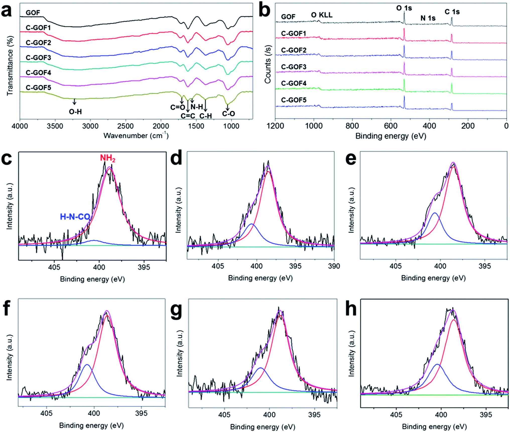 | ||
| Fig. 3 Characterization of the amidation reaction. (a) Fourier transform-infrared spectra and (b) wide-scan X-ray photoelectron spectra of GOF and C-GOFs. Deconvoluted high-resolution N1s signal for (c) GOF, (d) C-GOF1, (e) C-GOF2, (f) C-GOF3, (g) C-GOF4, and (h) C-GOF5. | ||
The thermal decomposition behavior of the GOFs, which was examined using TGA and DSC analyses, also supported crosslinking between GO and chitosan. Fig. 4a shows the amount of residual carbon from the GOFs after thermal decomposition of oxygen-containing functional groups derived from the chitosan present in the GOFs. The amount of polymer in the GO fibers was measured by thermogravimetric analysis. Measuring the remnant of the samples after 500 °C (Fig. 4b), the amount of polymer contained in GOF, C-GOF1, C-GOF2, C-GOF3, C-GOF4, and C-GOF5 was measured to be 3.5, 4.8, 5.2, 4.9, 5.1, and 5.3 wt%, respectively. The crosslinking reaction brought about tightly bounded-chitosan, and the fraction of chitosan in the fiber was slightly increased.
 | ||
| Fig. 4 Thermal decomposition behaviors of raw materials and GOFs. (a) Full temperature range and (b) near 500 degrees of thermogravimetric curves. (c) Differential scanning calorimetry curves. | ||
The onset temperature for thermal decomposition of the C-GOFs was considerably lower (173–175 °C) than those of GO and chitosan (183 °C and 276 °C, respectively), and the onset of decomposition of GOF occurred at 195 °C. Likewise, the exothermic DSC peak observed for GO at 201 °C due to thermal decomposition shifted to 191–197 °C (C-GOFs) and 212 °C (GOF) as a result of fiber formation and the chemical reaction (Fig. 4c). The decrease of the thermal decomposition temperature of the C-GOFs is attributed to a synergistic interaction between covalently bonded GO and chitosan molecules.40,41 Additionally, the lower thermal decomposition temperature of GOF is attributed to disruption of hydrogen bonds between the GO layers.42 Our experimental results clearly indicate that amide crosslinking groups successfully formed between the GO and chitosan.
3.4. Effects of the amidation reaction
The improved structural stability provided by the amidation reaction was evaluated using a swelling test of the GOFs in distilled water. Thickness changes over time were monitored using the optical microscope. Fig. S5† shows that the diameter of the GOFs instantaneously increased upon contact with water, and this increase continued over the next hour. In contrast, even as the soaking time increased, the chemically crosslinked samples (C-GOFs) hardly swelled because the GO flakes were immobilized. The considerable swelling of the GOFs is shown in Fig. 5a, while Fig. 5b shows the more limited swelling behavior observed as the crosslinking reaction time increased. | ||
| Fig. 5 Diameter change of GOFs soaked in distilled water with increasing time during the swelling test. (a) Long and (b) short soaking times. | ||
Tensile testing was used to quantitatively assess the structural stability provided by the crosslinking. Typical stress–strain curves of the GOFs indicated the improved mechanical properties of the C-GOFs compared with GOFs (Fig. 6a). The fracture load of the GO fibers in single fiber tensile tests was about 0.1 N. Load variation due to noise (e.g., machine vibration) during the tensile test was about 0.001 N, affecting high fluctuations in the tensile. We believe that the clamp and fracture did not affect the fluctuations. Young's modulus and tensile strength of composite fibers tend to increase with increased crosslinking density, while the breakage elongation tends to decrease. However, the effect of crosslinking reaction between GOs and chitosan on the breakage elongation was quite different. This is presumably due to the crosslinking reaction mostly occurring on the edges of GO flakes since the carboxyl group is mainly present at the edge of the GO flakes.43 This seemed to connect GO particles in the axial direction, playing a similar role reducing defects of the fibers.44 As a result, Young's modulus, tensile strength, and breakage elongation were improved simultaneously by the amidation reaction.44,45 This effect could be observed only for the small amount of crosslinking. As the crosslinking density increased beyond an optimum, the breakage elongation decreased. These properties are compared in detail in Fig. 6b–e. The Young's modulus of all GOFs increased according to differences between hydrogen bonding in the GOFs and covalent amide bonding in the C-GOFs (Fig. 6b). Fig. 6c and d shows that the tensile strength and breaking strain increased as the amidation time increased from 2 to 3 h, but these properties decreased at amidation reaction times greater than 3 h. The average tensile strength of C-GOF3 (129.6 ± 26.4 MPa) was 41.6% higher than that of GOF (91.5 ± 15.2 MPa), while the average elongation at break of C-GOF3 (4.03 ± 0.97%) was 75.2% higher than that of GOF (2.30 ± 0.40%). Although it was expected that better mechanical properties would be obtained with higher crosslinking density, the best properties were observed at an amidation reaction time of 2–3 h. The same behavior was reported for the crosslinked chitosan system32,46 and can be explained by the increased rigidity of over-crosslinked chitosan molecules.47 We conclude that the optimum amidation reaction time in our process was 2–3 h. The toughness curve in Fig. 6e has a pronounced parabolic shape, which is attributed to a synergistic effect between the strength and breaking strain. Notably, the toughness of C-GOF3 (1.253 ± 0.447 MJ m−3) was significantly greater (by 99.1%) than that of GOF (2.495 ± 0.585 MJ m−3), and the percentage improvement in toughness was much greater than that observed for the tensile strength and breaking strain.
 | ||
| Fig. 6 Mechanical properties of the GOFs. (a) Typical stress–strain curves, (b) Young's modulus, (c) tensile strength, (d) elongation at break, and (e) toughness. | ||
The fracture surface of the GOFs was observed using SEM to qualitatively understand the improved toughness (Fig. 7). The low-magnification SEM images show the flat cross-sectional surfaces of the GOFs. The high-resolution images of the C-GOFs show highly toughened cross-sections of the pulled-out parts (highlighted in yellow), while the GOF fibers were sharply cut without significant pull-out. The C-GOF2 and C-GOF3 in Fig. 7f and h displayed large protrusion areas because of effective load transfer by the optimal crosslinking density.
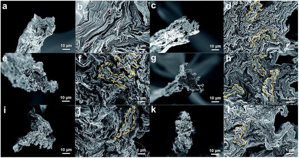 | ||
| Fig. 7 Low and high magnification field-emission scanning electron microscopy images of fractured cross-sectional surfaces of GOFs and C-GOFs. (a and b) GOFs, (c and d) C-GOF1, (e and f) C-GOF2, (g and h) C-GOF3, (i and j) C-GOF4, and (k and l) C-GOF5. | ||
4. Conclusions
More structurally and mechanically robust GOFs were manufactured by crosslinking them in the coagulation bath during the wet-spinning process. Carboxylic acid groups on GO flakes and amine groups on chitosan molecules crosslinked to form amide bonds through the EDC/NHS amidation mechanism; FT-IR, XPS, and TGA/DSC analyses confirmed the crosslinking. The structural and mechanical robustness of the modified GOFs were demonstrated by swelling and tensile tests. An amidation reaction time of 2–3 h provided fibers having the best mechanical properties. The toughness of the GOFs exposed to the amidation reaction time of 3 h was 99.1% higher than that of GOFs not exposed to the amidation reaction.Conflicts of interest
There are no conflicts to declare.Acknowledgements
This work was supported by a National Research Foundation of Korea (NRF) grant funded by the Ministry of Education (MOE) (NRF-2016R1D1A1B03935554) and by an NRF grant funded by the Ministry of Science and ICT (NRF-2015R1A5A1037627). This work was also supported by Nano Material Technology Development Program through NRF funded by Ministry of Science and ICT (NRF-2018M3A7B4089679). The Institute of Engineering Research at Seoul National University provided research facilities for this work.Notes and references
- Z. Xu and C. Gao, Mater. Today, 2015, 18, 480–492 CrossRef CAS.
- R. Bacon, J. Appl. Phys., 1960, 31, 283–290 CrossRef.
- C. Lee, X. Wei, J. W. Kysar and J. Hone, Science, 2008, 321, 385–388 CrossRef CAS PubMed.
- S. K. Hong, K. Y. Kim, T. Y. Kim, J. H. Kim, S. W. Park, J. H. Kim and B. J. Cho, Nanotechnology, 2012, 23, 455704 CrossRef PubMed.
- J. H. Seol, I. Jo, A. L. Moore, L. Lindsay, Z. H. Aitken, M. T. Pettes, X. Li, Z. Yao, R. Huang, D. Broido, N. Mingo, R. S. Ruoff and L. Shi, Science, 2010, 328, 213–216 CrossRef CAS PubMed.
- J. E. Kim, T. H. Han, S. H. Lee, J. Y. Kim, C. W. Ahn, J. M. Yun and S. O. Kim, Angew. Chem., Int. Ed., 2011, 50, 3043–3047 CrossRef CAS PubMed.
- Z. Xu and C. Gao, Nat. Commun., 2011, 2, 571 CrossRef PubMed.
- L. Onsager, Ann. N. Y. Acad. Sci., 1949, 51, 627–659 CrossRef CAS.
- D. Frenkel and R. Eppenga, Phys. Rev. Lett., 1982, 49, 1089 CrossRef CAS.
- Z. Xu, Y. Liu, X. Zhao, L. Peng, H. Sun, Y. Xu, X. Ren, C. Jin, P. Xu, M. Wang and C. Gao, Adv. Mater., 2016, 28, 6449–6456 CrossRef CAS PubMed.
- Y. Yin, T. Wang, R. Huang, Y. Zhang and C. Wang, J. Mater. Chem. C, 2018, 6, 13261–13268 RSC.
- C. Hua, Y. Shang, X. Li, X. Hu, Y. Wang, X. Wang, Y. Zhang, X. Li, H. Duan and A. Cao, Nanoscale, 2016, 8, 10659–10668 RSC.
- X. Liu, D. Liu, J.-h. Lee, Q. Zheng, X. Du, X. Zhang, H. Xu, Z. Wang, Y. Wu and X. Shen, ACS Appl. Mater. Interfaces, 2018, 11, 2282–2294 CrossRef PubMed.
- Q. Liu, M. Zhang, L. Huang, Y. Li, J. Chen, C. Li and G. Shi, ACS Nano, 2015, 9, 12320–12326 CrossRef CAS PubMed.
- L. Kou, T. Huang, B. Zheng, Y. Han, X. Zhao, K. Gopalsamy, H. Sun and C. Gao, Nat. Commun., 2014, 5, 3754 CrossRef CAS PubMed.
- Y. Jia, L. Zhou and J. Shao, Synth. Met., 2018, 246, 108–114 CrossRef CAS.
- B. Li, J. Cheng, Z. Wang, Y. Li, W. Ni and B. Wang, J. Power Sources, 2018, 376, 117–124 CrossRef CAS.
- J.-G. Lee, Y. Kwon, J.-Y. Ju, S. Choi, Y. Kang, W.-R. Yu and D. W. Kim, J. Appl. Electrochem., 2017, 47, 865–875 CrossRef CAS.
- M. Gu, S. Ko, S. Yoo, E. Lee, S. H. Min, S. Park and B.-S. Kim, J. Power Sources, 2015, 300, 351–357 CrossRef CAS.
- G. Xin, T. Yao, H. Sun, S. M. Scott, D. Shao, G. Wang and J. Lian, Science, 2015, 349, 1083–1087 CrossRef CAS PubMed.
- X. Wang, J. Peng, Y. Zhang, M. Li, E. Saiz, A. P. Tomsia and Q. Cheng, ACS Nano, 2018, 12, 12638–12645 CrossRef CAS PubMed.
- Y. S. Kim, J. H. Kang, T. Kim, Y. Jung, K. Lee, J. Y. Oh, J. Park and C. R. Park, Chem. Mater., 2014, 26, 5549–5555 CrossRef CAS.
- X. Hu, Z. Xu and C. Gao, Sci. Rep., 2012, 2, 767 CrossRef PubMed.
- Z. Xu, H. Sun, X. Zhao and C. Gao, Adv. Mater., 2013, 25, 188–193 CrossRef CAS PubMed.
- C. Xiang, C. C. Young, X. Wang, Z. Yan, C. C. Hwang, G. Cerioti, J. Lin, J. Kono, M. Pasquali and J. M. Tour, Adv. Mater., 2013, 25, 4592–4597 CrossRef CAS PubMed.
- V. R. Pattabiraman and J. W. Bode, Nature, 2011, 480, 471 CrossRef CAS PubMed.
- N. Behabtu, J. R. Lomeda, M. J. Green, A. L. Higginbotham, A. Sinitskii, D. V. Kosynkin, D. Tsentalovich, A. N. G. Parra-Vasquez, J. Schmidt and E. Kesselman, Nat. Nanotechnol., 2010, 5, 406–411 CrossRef CAS PubMed.
- C. Wang, Q. Yan, H.-B. Liu, X.-H. Zhou and S.-J. Xiao, Langmuir, 2011, 27, 12058–12068 CrossRef CAS PubMed.
- M. Naebe, J. Wang, A. Amini, H. Khayyam, N. Hameed, L. H. Li, Y. Chen and B. Fox, Sci. Rep., 2014, 4, 4375 CrossRef PubMed.
- S. B. Qasim, S. Najeeb, R. M. Delaine-Smith, A. Rawlinson and I. Ur Rehman, Dent. Mater., 2017, 33, 71–83 CrossRef CAS PubMed.
- J. Bart, R. Tiggelaar, M. Yang, S. Schlautmann, H. Zuilhof and H. Gardeniers, Lab Chip, 2009, 9, 3481–3488 RSC.
- W. Cui, M. Li, J. Liu, B. Wang, C. Zhang, L. Jiang and Q. Cheng, ACS Nano, 2014, 8, 9511–9517 CrossRef CAS PubMed.
- R. Jalili, S. H. Aboutalebi, D. Esrafilzadeh, R. L. Shepherd, J. Chen, S. Aminorroaya-Yamini, K. Konstantinov, A. I. Minett, J. M. Razal and G. G. Wallace, Adv. Funct. Mater., 2013, 23, 5345–5354 CrossRef CAS.
- H.-P. Cong, X.-C. Ren, P. Wang and S.-H. Yu, Sci. Rep., 2012, 2, 613 CrossRef PubMed.
- S. K. Mishra, S. N. Tripathi, V. Choudhary and B. D. Gupta, Plasmonics, 2015, 10, 1147–1157 CrossRef CAS.
- H. Yu, B. Zhang, C. Bulin, R. Li and R. Xing, Sci. Rep., 2016, 6, 36143 CrossRef CAS PubMed.
- Y. M. Shulga, V. M. Martynenko, V. E. Muradyan, S. A. Baskakov, V. A. Smirnov and G. L. Gutsev, Chem. Phys. Lett., 2010, 498, 287–291 CrossRef CAS.
- S. Devaramani, P. S. Adarakatti and P. Malingappa, Electrochim. Acta, 2017, 231, 650–658 CrossRef CAS.
- J. F. Moulder, Physical Electronics, 1995, 230–232 Search PubMed.
- F. Barroso-Bujans, A. Alegría, J. A. Pomposo and J. Colmenero, Macromolecules, 2013, 46, 1890–1898 CrossRef CAS.
- M. Li, H. Song, X. Chen, J. Zhou and Z. Ma, Phys. Chem. Chem. Phys., 2015, 17, 3250–3260 RSC.
- J.-L. Hong, X.-H. Zhang, R.-J. Wei, Q. Wang, Z.-Q. Fan and G.-R. Qi, J. Appl. Polym. Sci., 2014, 131, 39847 Search PubMed.
- B. Konkena and S. Vasudevan, Langmuir, 2012, 28, 12432–12437 CrossRef CAS PubMed.
- S. Park, K.-S. Lee, G. Bozoklu, W. Cai, S. T. Nguyen and R. S. Ruoff, ACS Nano, 2008, 2, 572–578 CrossRef CAS PubMed.
- N. Hu, L. Meng, R. Gao, Y. Wang, J. Chai, Z. Yang, E. S.-W. Kong and Y. Zhang, Nano-Micro Lett., 2011, 3, 215–222 CrossRef CAS.
- M.-C. Chen, C.-T. Liu, H.-W. Tsai, W.-Y. Lai, Y. Chang and H.-W. Sung, Biomaterials, 2009, 30, 5560–5571 CrossRef CAS PubMed.
- D. Nataraj, S. Sakkara, M. Meghwal and N. Reddy, Int. J. Biol. Macromol., 2018, 120, 1256–1264 CrossRef CAS PubMed.
Footnotes |
| † Electronic supplementary information (ESI) available: Morphology of the GO flakes, POM image in Fig. S1; FT-IR and XPS spectra of GO and chitosan in Fig. S2; microscopic images of GO-chitosan pre-crosslinked solution in Fig. S3; side view of fractured surface images in Fig. S4; time-lapse swelling behavior of GOFs in Fig. S5. See DOI: 10.1039/c9ra03945g |
| ‡ These authors contributed equally. |
| This journal is © The Royal Society of Chemistry 2019 |