
 Open Access Article
 This Open Access Article is licensed under a Creative Commons Attribution-Non Commercial 3.0 Unported Licence
Synthesis of calcium carbonate microcapsules as self-healing containers†
Nadeesha Maduwanthi Hettiarachchia,
Rangika Thilan De Silva *ab,
M. M. M. G. Prasanga Gayanath Mantilakaab,
Pooria Pasbakhshc,
K. M. Nalin De Silvaabd and
Gehan A. J. Amaratungaabe
*ab,
M. M. M. G. Prasanga Gayanath Mantilakaab,
Pooria Pasbakhshc,
K. M. Nalin De Silvaabd and
Gehan A. J. Amaratungaabe
aAcademy of Sri Lanka Institute of Nanotechnology (SLINTEC Academy), Nanotechnology and Science Park, Mahenwatta, Pitipana, Homagama, 10200, Sri Lanka. E-mail: rangikaDS@slintec.lk
bSri Lanka Institute of Nanotechnology (SLINTEC), Nanotechnology and Science Park, Mahenwatte, Pitipana, Homagama, 10200, Sri Lanka
cMechanical Engineering Discipline, School of Engineering, Monash University Malaysia, Jalan Lagoon Selatan, Bandar Sunway, 47500 Selangor, Malaysia
dDepartment of Chemistry, Faculty of Science, University of Colombo, Colombo 00300, Sri Lanka
eElectrical Engineering Division, Department of Engineering, University of Cambridge, 9 J. J. Thomson Avenue, Cambridge CB3 0FA, UK
First published on 30th July 2019
Abstract
Contemporary studies of self-healing polymer composites are based on microcapsules synthesized using synthetic and toxic polymers, biopolymers, etc. via methods such as in situ polymerization, electrospraying, and air atomization. Herein, we synthesized a healing agent, epoxy (EPX) encapsulated calcium carbonate (CC) microcapsules, which was used to prepare self-healing EPX composites as a protective coating for metals. The CC microcapsules were synthesized using two facile methods, namely, the soft-template method (STM) and the in situ emulsion method (EM). Microcapsules prepared using the STM (ST-CC) were synthesized using sodium dodecyl sulphate (SDS) surfactant micelles as the soft-template, while the microcapsules prepared using the EM (EM-CC) were synthesized in an oil-in-water (O/W) in situ emulsion. These prepared CC microcapsules were characterized using light microscopy (LMC), field emission scanning electron microscopy (FE-SEM), fourier transform infrared spectroscopy (FTIR), nuclear magnetic resonance spectroscopy (NMR), and thermogravimetric analysis (TGA). The synthesized ST-CC microcapsules were spherical in shape, with an average diameter of 2.5 μm and an average shell wall thickness of 650 nm, while EM-CC microcapsules had a near-spherical shape with an average diameter of 3.4 μm and an average shell wall thickness of 880 nm. The ST-CC capsules exhibited flake-like rough surfaces while EM-CC capsules showed smooth bulgy surfaces. The loading capacity of ST-CC and EM-CC microcapsules were estimated using TGA and found to be 11% and 36%, respectively. The FTIR and NMR spectra confirmed the EPX encapsulation and the unreactive nature of the loaded EPX with the inner walls of CC microcapsules. The synthesized CC microcapsules were further incorporated into an EPX matrix to prepare composite coatings with 10 (w/w%), 20 (w/w%), and 50 (w/w%) capsule loadings. The prepared EPX composite coatings were scratched and observed using FE-SEM and LMC to evaluate the release of encapsulated EPX inside the CC capsules, which is analogous to the healing behaviour. Moreover, EPX composite coatings with 20 (w/w%) and 50 (w/w%) of ST-CC showed better healing performances. Thus, it was observed that ST-CC microcapsules outperformed EM-CC. Additionally, the EPX/CC coatings showed remarkable self-healing properties by closing the gaps of the scratch surfaces. Thus, these formaldehyde-free, biocompatible, biodegradable, and non-toxic CC based EPX composite coatings hold great potential to be used as a protective coating for metal substrates. Primary results detected significant corrosion retardancy due to the self-healing coatings under an accelerated corrosion process, which was performed with a salt spray test.
Introduction
Self-healing polymer composites are inspired by biological systems to autonomously repair the fractures of the composite materials. Typically, the impaired polymer materials are refurbished through patching, which is limited to the accuracy allowed by visual inspection. Besides, these methods are neither autonomic nor near-instantaneous as an assessment is required. Inaccessible brittle microcracks occur and propagate due to the harsh environmental conditions and externally induced stresses, which are difficult to control. Relatively, microcracking is one of the most challenging problems that can lead to a catastrophic failure of composites and hence shorten their life span.1 Therefore, self-healing polymer composites have been proposed as a route for solving the problem of microcracking.1–3 The self-healing polymers are a class of smart materials that are designed to have the inherent ability to recover from damages.4 The most important and challenging aspect of self-healing composite systems is to develop an effective system to carry the healing agents inside the polymeric matrix. The carrier system (mostly nano/microcapsules in the capsule-based system) should be strong enough to survive the manufacturing processes (such as mixing, curing, extrusion, etc.) without releasing the healing agents.5 On the other hand, it should break during the propagation of cracks inside the matrix and release an adequate amount of active healing agents into the crack planes to heal the damage.Different self-healing mechanisms have been researched, including extrinsic and intrinsic self-healing. The extrinsic self-healing can be broken down into the capsule and vascular-based self-healing systems.6,7 In an ideal self-healing polymer composite mono-capsule system, the healing agent is encapsulated within a nano/microcapsule, and it is released into the matrix crack spaces upon the intrusion of a crack into the microcapsule, which triggers the healing process in the presence of a catalyst in the matrix. In the dual-capsule self-healing polymer composite system, the healing agent (monomer) and hardener (cross-linking/curing agent) are separately loaded into the nano/microcapsule and released into the matrix crack upon its intrusion into the shell of the microcapsule in order to begin the healing process. One of the first autonomous self-healing EPX composite systems was reported by White et al.,8 wherein the healing agent (dicyclopentadiene (DCPD)) was loaded into microcapsules while having a solid-phase catalyst (Grubbs catalyst) in the EPX matrix. Apart from the capsule-based self-healing systems, the vascular-based self-healing systems have also been studied to introduce multiple recoveries (healing ability upon cyclic loading/repetitive fractures).5 Capillaries or fibers can also be embedded within the polymer matrix for self-healing. Vahedi et al.6,9 impregnated healing and curing agents into polyacrylonitrile (PAN) electrospun nanofibrous mats (vascular fibrous structure) and obtained 75% healing efficiency at 50 °C even after the 2nd loading cycle.9 Thus, improving the healing ability of composites after the initial crack formation (i.e. multiple recovery cycles) has also become a current research interest.
The capsule-based self-healing system is attractive due to its ease of use without any alteration in the properties of the polymer matrix. Ahangaran et al. synthesized EPX and mercaptan catalyst encapsulated poly(methyl methacrylate) (PMMA) microcapsules as a dual-component healing system and achieved 80% healing efficiency with 10 wt% PMMA microcapsule loading at room temperature after 24 h.10 However, most of the capsule-based self-healing systems have utilized toxic polymers, mainly formaldehyde, in the early studies for fabricating capsules. Also, urea-formaldehyde (UF),8,11,12 polyurethane/urea-formaldehyde (PUF),8,13–15 poly(melamine-formaldehyde) (PMF),14,16 and melamine-formaldehyde (MF)17 capsules have been used as the shell material of the containers carrying the healing agents through in situ polymerization processes. These formaldehyde containers have fairly complex synthesizing pathways based on the number of parameters that have to be maintained (pH, temperature, loading, etc.)8,13,16 and are toxic to living organisms.18,19 This has led to the exploration of non-toxic materials such as biopolymers and minerals to synthesize capsules. Different biopolymers such as alginate18,20,21 and chitosan20 have been used to fabricate containers for carrying self-healing agents. Particularly, alginate has been found to be a promising biopolymer for the formaldehyde-free capsule-based self-healing system, which is also relatively low-cost and synthesized simply without temperature and pH alterations.22 Moreover, they can heal up to 3 times due to the multi-core microcapsule structure.18 Although numerous biopolymer capsule-based self-healing polymers have been reported, not much research has been focused on the synthesis of mineral-based capsules for self-healing EPX composites. To the best of our knowledge, no research work has been carried out utilizing CC nano/microcapsules in order to evaluate the self-healing performance of the EPX composite systems. The CC microcapsules have a number of desirable properties such as biocompatibility,23–25 biodegradability,23–26 and non-toxicity.23,24 Usually, the CC coatings are prepared by using precursor solutions of CaCl2 and Na2CO3 simultaneously, which is a simple and cost-effective process.23,27
Generally, metals and alloys are used in the construction of buildings, bridges, and pipelines, which are prone to rust upon contact with the atmospheric moisture. The polymeric coatings on metals can act as barriers to hinder corrosion.5,28 However, the protective coatings being the outer layer are prone to damages during transportation, installation, and maintenance, leading to the re-exposure of the metal substrates. To overcome this drawback, the self-healing composite coatings on metals have incorporated microcapsules, which can release healing agents once broken. Then, the outermost coating damages can be healed, and the corrosion barrier properties can be maintained. For example, Huang et al. fabricated hexamethylene diisocyanate encapsulated polyurethane (PU) microcapsules through interfacial polymerization having diameters of 5–350 μm and shell thickness of 1–15 μm. The anticorrosive coatings mixed with synthesized microcapsules were applied on a metal plate and shown to maintain corrosion retardant properties under an accelerated corrosion test.29 The triazole derivative filled PU microcapsules had been used for self-healing corrosion protection coating using an interfacial polymerization of diol-diisocyanate and 1,4-butanediol (BD). The PU microcapsule loaded coatings showed better anti-corrosion properties under the salt spray test.30 Guin et al. also encapsulated methyl diphenyl diisocyanate within nano-sized capsules (100–800 nm) using an in situ UF polymerization technique. Those were incorporated into the sol–gel matrix to prepare a self-healing anticorrosive coating, and it exhibited high conductivity (24![[thin space (1/6-em)]](https://www.rsc.org/images/entities/char_2009.gif) 875 ohm cm−2) compared to that of the conventional coating (43625 ohm cm−2).31 The polymeric coatings applied on marine and offshore structures, underground pipelines, and steam conduits, which are continuously exposed to aqueous and/or corrosive environments, particularly require the inclusion of self-healing capsules to enhance their service life.32–37
875 ohm cm−2) compared to that of the conventional coating (43625 ohm cm−2).31 The polymeric coatings applied on marine and offshore structures, underground pipelines, and steam conduits, which are continuously exposed to aqueous and/or corrosive environments, particularly require the inclusion of self-healing capsules to enhance their service life.32–37
The objective of this work is to synthesize CC microcapsules as containers to be used in capsule-based self-healing EPX polymers. Two different approaches were used to synthesize CC microcapsules in order to encapsulate the EPX healing agent and hardener, namely, in situ emulsion method (EM-CC) and soft-template method (ST-CC). In this work, ARALDITE 506 as the healing agent was loaded into ST-CC and EM-CC microcapsules, which were then incorporated into a polymer matrix (EPX) to obtain thin self-healing EPX composite coatings, which acts as a barrier to metal corrosions. The properties of microcapsules such as size, surface morphology, thermal expansion, loading capacity/core content, and chemical properties were assessed. Further, the self-healing ability of the composite coatings loaded with 10, 20, and 50 (w/w%) of microcapsules were evaluated. Thus, these EPX loaded, toxic formaldehyde-free CC microcapsules can act as effective self-healing protective corrosion barrier layer on metals.
Experimental
Materials and reagents
Two forms of epoxy resins (diglycidyl ether of bisphenol A), EPIKOTE 828 (12000–14000 cps at 25 °C) and ARALDITE 506 (500–700 cps at 25 °C), were used as an epoxy matrix and as capsule core material, respectively. Diethylenetriamine (99%, DETA) as the hardener, ethanol (60%), acetone, calcium chloride (99.5%), sodium carbonate (99.5–100.5%), sodium dodecyl sulphate (SDS, 98.5%), sodium chloride (NaCl, 99.5%), and cetyltrimethylammonium chloride solution (CTAC, 25%) were purchased from Sigma Aldrich. All chemicals and reagents were of analytical grade and used without further purification. All solutions were prepared using distilled water.
Microcapsule preparation
Fig. 1(a) demonstrates the synthesis process of ST-CC microcapsules, into which EPX was loaded using vacuum evacuation at ambient temperature. Initially, 100 mL of 0.33 M Na2CO3 and 0.5% SDS were mixed by stirring for 20 minutes. Then, 100 mL of 0.33 M CaCl2 was added to the resultant mixture and stirred well for another 20 minutes. The mixture was then left undisturbed to settle down and the supernatant was removed. Afterwards, the microcapsules were washed with distilled water and oven-dried at 60 °C overnight. Eventually, the ST-CC hollow microcapsules were obtained after the heat treatment, carried out at 500 °C for 2 h, which removed the surfactant. Those ST-CC hollow microcapsules were encapsulated with the EPX resin polymer (ARALDITE 506) using a vacuum evacuation process (vacuum pressure of 1.5 mbar for 120 minutes, repeated for 2 cycles). Fig. 1(b) depicts the formation mechanism of ST-CC microcapsules.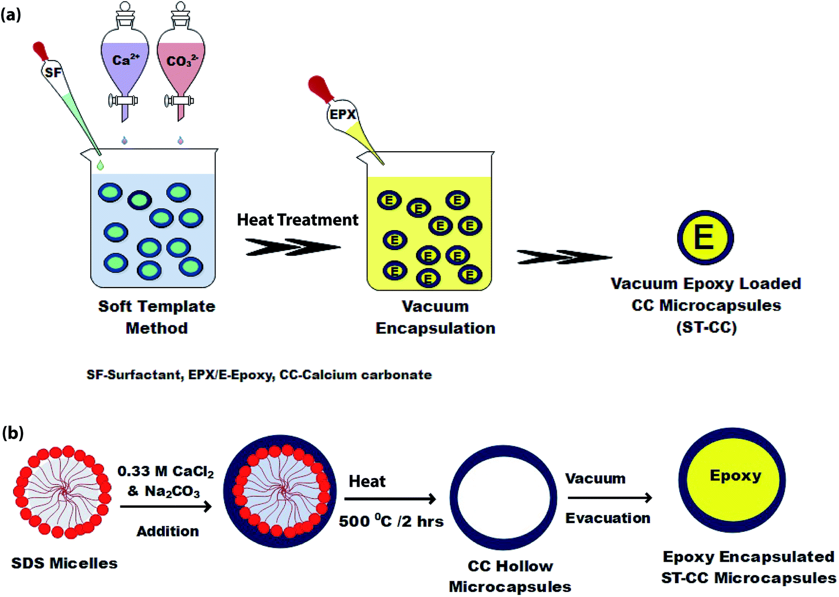 | ||
| Fig. 1 The schematic of ST-CC microcapsules synthesized by STM, (a) process steps, and (b) the formation mechanism. | ||
In Fig. 2(a), the synthesis process of an in situ encapsulated EPX resin (ARALDITE 506) in CC (EM-CC) microcapsules, which were prepared using the oil-in-water (O/W) emulsion method at ambient temperature, is shown. 100 mL of distilled water and 1 mL of EPX resin were mixed at room temperature. Subsequently, 0.5% of CTAC was added into the emulsion mixture while agitating and the resulting mixture was continuously stirred for 150 min. Then, the precursor solutions of CC, which contain calcium chloride and sodium carbonate (0.1 M, 50 mL each), were added dropwise for 30 min simultaneously. The mixture was kept aside to settle, after which the supernatant solution was removed. The remaining microcapsules (EM-CC) were dried overnight at room temperature. Fig. 2(b) shows the formation mechanism of EM-CC microcapsules.
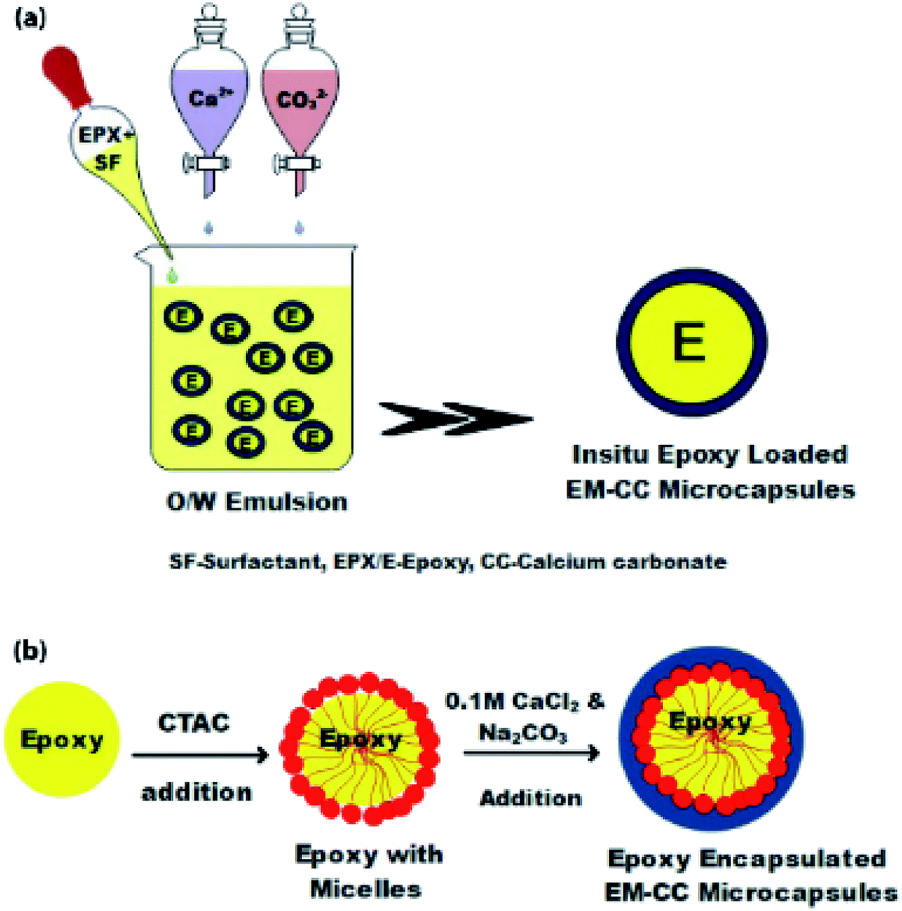 | ||
| Fig. 2 The schematic of EM-CC microcapsules synthesized by EM, (a) process steps, and (b) the formation mechanism. | ||
Fabrication of CC microcapsule loaded EPX composite thin coatings
The EPX composite thin-coatings were fabricated by dispersing microcapsules (10 wt%, 20 wt%, and 50 wt% of ST-CC and EM-CC, separately) in the matrix with EPIKOTE 828 and DETA at a ratio of 100:12. The polymer mixture with microcapsules was gently stirred prior to degassing and then coated onto the cleaned metal plates (1 × 1 × 0.2 cm) using the doctor blade method. It was fully cured overnight at 30 °C prior to further testing. Before coating, the metal plates were cleaned with sandpaper and washed with acetone, followed by the application of the coating mixture. The thickness of the coating was about 500 μm. The samples were prepared by coating the metal substrate with composite coatings containing 10 wt%, 20 wt%, and 50 wt% of EM-CC and ST-CC separately. Control samples were also prepared without microcapsules in the same manner for comparison purposes. The specimens were scratched with a sharp blade and left for 24 h before characterizing them with FE-SEM and LMC to identify the releasing ability of the healing agents and to assess the self-healing performance. The salt spray-based corrosion test was also carried out on the EPX composite coating loaded with 50 wt% of the synthesized ST-CC microcapsules.
Characterization
The morphological characterization of both synthesized microcapsules (ST-CC and EM-CC) and composite thin coatings on the metal substrate were done using a Hitachi SU6600 field emission scanning electron microscope (FE-SEM) (gold was sputtered on microcapsule samples only to observe the size, morphology, and shell wall thickness). The average microcapsule sizes and the thickness of the shell wall of synthesized CC microcapsules were derived from the statistics of at least 25 measurements using Image J software on the FE-SEM images. The microcapsules were placed on a carbon conductive tape, and some of them were ruptured with a blade to observe the core–shell structure.Wet microcapsules and thin polymer composite coatings were analyzed using a light microscope (LMC) at various magnifications (OLYMPUS BX61).
Thermogravimetric analysis (TGA SDTQ-600) was used to determine the loading capacity of the prepared EPX encapsulated microcapsules (ST-CC and EM-CC) after washing with acetone. 10–15 mg of microcapsules were heated in a nitrogen atmosphere at a rate of 10 °C min−1 from 30 °C to 600 °C.38 The loading capacity of microcapsules was derived by considering the weight losses of microcapsules between 100–600 °C.18
Fourier Transform Infrared Spectroscopy ((FT-IR) Bruker Vertex 80 spectrometer) and Nuclear Magnetic Resonance Spectroscopy ((NMR) Bruker Ascend 400 MHz) were used to determine the chemical properties of the microcapsules in order to confirm the encapsulation of EPX resin within the prepared CC microcapsules. Further, the attenuated total reflectance (ATR) measurement mode was used to record the absorbance spectra in 64 scans in the range of 400–4000 cm−1 wavenumber with a resolution of 4 cm−1.
The composite thin coatings on the metal substrate after 24 h of scratching were characterized with FE-SEM (without sputtering with gold). Light microscopy was also used to image the scratched areas of the thin composite coatings on glass slides to check the polymer's releasing ability when the microcapsules were broken.
The salt spray-based corrosion studies were carried out on the metal plates (4 × 3 × 0.2 cm) coated with EPX composite loaded with 50 wt% ST-CC. The coated specimens were sprayed with 0.1 M NaCl solution and kept for 48 h to evaluate the accelerated corrosion process.
Results and discussion
Microcapsule formation mechanism
The ST method was used to produce ST-CC microcapsules, which utilizes surfactant (SDS) micelles as the soft-template, with a coating of CC on the micelles by using its precursor solutions. The SDS surfactant micelles formed a spherical shape in aqueous media due to the balance of the forces between the polar head part and non-polar tail part, thereby promoting the micelle formation.39 Fig. 1(b) illustrates the physical interaction between the micelles and precursor ions such as Ca2+ and CO32−. The ST-CC hollow microcapsules formed were dipped in an excess amount of EPX resin. All the trapped gases within the hollow CC microcapsules were removed by vacuum and refilled with EPX resin polymer. Subsequently, the vacuum supply was removed after the discontinuation of the air bubble formation in the viscous slurry during encapsulation. These ST-CC microcapsules were used in self-healing composite applications. The EM-CC was prepared using surfactant (CTAC) micelles and CC precursor solutions, which are based on oil-in-water (O/W) EM without any polymerization. The micelles were formed as spheres between the EPX and water (Fig. 2(b)). The hydrophobic tails and hydrophilic heads of surfactants were arranged to form micelles (heads toward water and tails toward EPX). These micelles, which encapsulated the EPX polymer within their cores, were coated using CC precursor solutions simultaneously. The core–shell EM-CC microcapsules, which have liquid EPX resin core and solid CC shell, were prepared through an in situ process of emulsification between two different media.Morphological properties
Both types of microcapsules (ST-CC and EM-CC) were characterized to assess their morphology, loading capacity, and chemical and physical properties. Shell wall integrity and microcapsule sizes were measured using FE-SEM images. As shown in Fig. 3(a and b), microcapsules of ST-CC exhibited a spherical shape and rough flake-like surface with a mean diameter of ∼3.0 μm before heat treatment. The flake-like rough structure could be formed on the surfaces due to the slow transformation of the amorphous primary precipitate of CaCO3 into spherical microcapsules.23,40 The ST-CC outer coating thickness was ∼0.74 μm before heat treatment (Fig. S1(a); in ESI†). After heat treatment, the microcapsule surface has contracted to a mean diameter of ∼2.5 μm (Fig. 3(c)) and the thickness of the outer coating decreases to ∼0.65 μm (Fig. S1(b); in ESI†). These rough surfaces showed a high surface area, which will facilitate better interaction with the polymer matrix during composite preparation. Pores were also observed on the surface of ST-CC microcapsules after heat treatment as a result of surfactant removal. These pores could be used for the encapsulation of the EPX polymer using the vacuum evacuation method (Fig. 3(c)). The pore sizes were in the range of 300–800 nm. The SEM images of the EM-CC microcapsules are shown in Fig. 3(e and f). They have a spherical shape with a mean diameter of ∼3.4 μm. The EM-CC outer coating thickness was ∼0.88 μm (Fig. S1 (c); in ESI†), which is a significantly high thickness value compared to that of ST-CC. Further, the shell walls of the microcapsules showed a rough appearance with a slightly bulgy surface (Fig. 3(e)). The SEM image in Fig. 3(f) gives evidence that the organic EPX polymer was encapsulated within the EM-CC microcapsules (images were taken after breaking it). These CC microcapsules were separated quickly from the water medium by pipetting out the supernatant within a few minutes after the mixing of precursors together. Both microcapsules have a high surface area due to flake-like or bulgy rough appearance. These structural and morphological characteristics of microcapsules were determined by the mechanism of their formation. It was found earlier41,42 that the growth of CC microcapsules is a type of colloidal aggregation of primary amorphous CC nanoparticles, which suddenly appears with the mixing of calcium chloride and sodium carbonate precursor solutions, into spherical micron-sized microcapsules. They may slowly recrystallize in water into rhombohedral calcite crystals with time. Thus, to get the porous CC microcapsules, the recrystallization process should be stopped at the spherical stage by filtering and thoroughly washing with water.42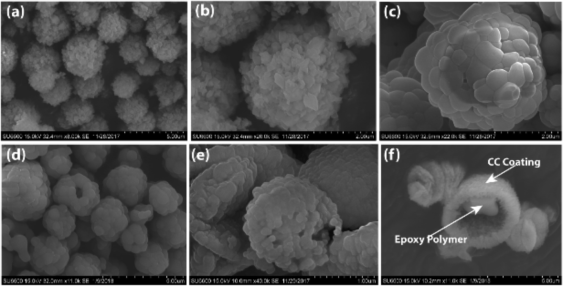 | ||
| Fig. 3 The FE-SEM images of ST-CC microcapsules (a and b) before heat treatment, (c) hollow microcapsules after heat treatment process, (d) after encapsulation of EPX by vacuum evacuation method, (e) EM-CC microcapsules with bulgy surface, and (f) the encapsulated EPX resin within EM-CC microcapsules after breaking it. | ||
Encapsulation efficacy
The loading capacity and the thermal stability of the EPX encapsulated microcapsules were assessed by tracking the mass losses of the hollow and loaded microcapsules with TGA after washing with acetone. The thermograms of the hollow ST-CC and EM-CC microcapsules (unloaded), filled ST-CC and EM-CC microcapsules (loaded), and EPX resin (ARALDITE 506) polymer are shown in Fig. 4. It can be seen that the thermal decomposition of both hollow and filled microcapsules have different thermograms. The hollow ST-CC microcapsules were used for the TGA analysis after heat treatment at 500 °C for 2 h. The total mass-loss was less than 1% from 50 to 600 °C, which corresponds to the loss of adsorbed moisture and the degradation of the residual surfactant that remained after the heat treatment. Thus, this indicates that the ST-CC hollow microcapsules had higher thermal stability compared to other CC microcapsules.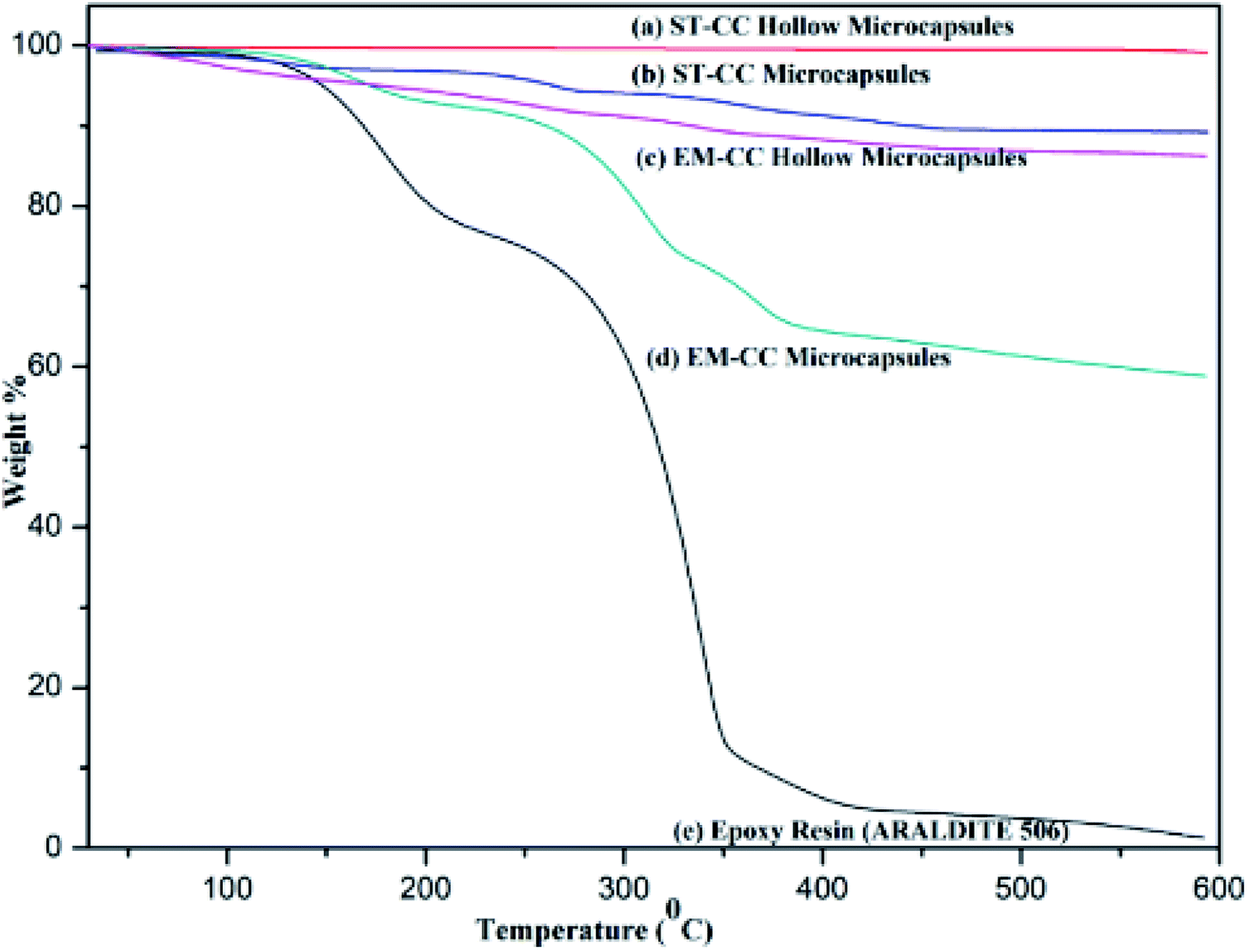 | ||
| Fig. 4 The thermogravimetric analysis (TGA) thermograms of (a) ST-CC hollow microcapsules, (b) ST-CC filled microcapsules, (c) EM-CC hollow microcapsules, (d) EM-CC filled microcapsules, and (e) EPX resin (ARALDITE 506) polymer. | ||
For the ST-CC microcapsules, the first mass loss of less than 1% below 100 °C corresponds to the absorbed moisture, and the subsequent 10% from 100–500 °C relates to the decomposition of uncured EPX resin polymer. The EM-CC hollow and filled microcapsules were subjected to the TGA analysis without heat treatment.
Therefore, the surfactant used for the synthesis of the microcapsule remains within the microcapsule. The initial mass-loss of EM-CC hollow microcapsules represents less than 2.25% below 100 °C and is related to the loss of moisture absorbed and high volatile polymer fraction of the surfactant. Consequent mass-losses were around 11.5%, which represented the decomposition of the residual surfactant from 100–600 °C. Indeed, the encapsulated EPX resin and surfactant were present together. So, the EM-CC microcapsules further lose about 36% of their mass due to the decomposition of the surfactant and uncured EPX resin polymer from 100–600 °C.
Amongst all the microcapsule types, the EM-CC microcapsules showed higher mass-loss due to high loading capacity. In essence, the increase in the loading capacity of EM-CC microcapsules occurs due to two types of organics (both epoxy and surfactant) including uncured EPX resin polymer which decomposes around 300 °C.43 The loading capacity of ST-CC microcapsules and EM-CC microcapsules were estimated to be 11% and 36%, respectively. The highest rate of mass-loss, estimated to be 65%, from pure EPX resin monomer thermogram was observed in the range of 200 to 400 °C. Such a severe loss in its mass was due to the decomposition of uncured EPX resin monomer at 300 °C.43 The thermal stability of the encapsulated EPX monomer within CC microcapsules was higher than that of pure EPX resin monomer, as demonstrated from the residual content at the end of TGA analysis from CC microcapsules and pure EPX resin monomer.
Fourier Transform Infrared Spectroscopy (FTIR) spectra of EPX resin (ARALDITE 506), ST-CC hollow microcapsules, ST-CC microcapsules, EM-CC microcapsules without polymer, and EM-CC microcapsules with polymer are illustrated in Fig. 5. There are two characteristic absorption bands of the oxirane ring, which are detected in the FTIR spectrum of the EPX resin polymer (ARALDITE 506) within the wavenumber range of 4000 cm−1 to 400 cm−1. The first one, at 915 cm−1, corresponds to the C–O stretching of the oxirane group. The second band, positioned at 3057 cm−1, can be ascribed to the C–H stretching of the methylene group of the EPX ring. The intensity of this band was low and was very close to that of the strong O–H absorptions. Nevertheless, it can be used as a qualitative indication of the presence of EPX groups in the low polymerized EPX monomers.44 However, major peaks of diglycidylether of bisphenol A at 3057 cm−1, 1607 cm−1, 1508 cm−1, 1033 cm−1, and 915 cm−1 (ref. 8 and 44) (Table 1) also appeared in the spectra of ST-CC and EM-CC microcapsules. The presence of these specific peaks of EPX resin in the spectra of ST-CC and EM-CC microcapsules confirms the encapsulation of EPX within the core of both the microcapsules. Any changes in the position of the peaks or intensity were not observed in the spectra of microcapsules with or without the polymer. This confirms that CC shell and EPX resin have not undergone any chemical reaction or interaction.
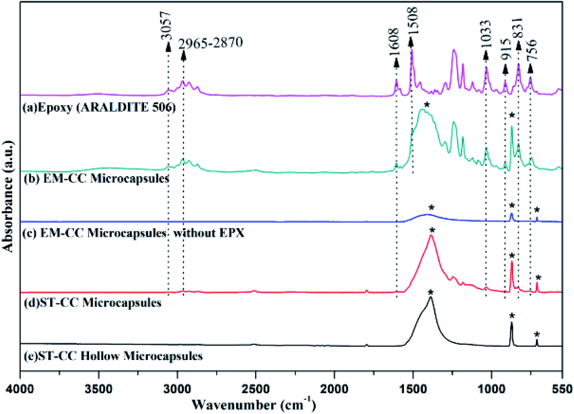 | ||
| Fig. 5 The FTIR spectra of (a) EPX resin (ARALDITE 506), (b) EM-CC microcapsules, (c) EM-CC microcapsules without EPX, (d) ST-CC microcapsules, and (e) ST-CC hollow microcapsules (* denotes similar peaks corresponding to CC shell material). | ||
| Band (cm−1) | Assignment |
|---|---|
| 3057 | Stretching vibration of C–H of the oxirane ring |
| 2965–2870 | Stretching C–H of CH2 and CH for aromatic and aliphatic |
| 1608 | Stretching vibration of C![[double bond, length as m-dash]](https://www.rsc.org/images/entities/char_e001.gif) C of aromatic rings C of aromatic rings |
| 1508 | Stretching vibration of C–C of aromatic rings |
| 1033 | Stretching vibration of C–O–C of oxirane ether group |
| 915 | Stretching vibration of C–O of oxirane group |
| 831 | Stretching vibration of C–O–C of oxirane group |
| 756 | Rocking vibration of CH2 |
Furthermore, the 13C NMR technique was also used to confirm the encapsulation. Fig. 6(a and b) shows the 13C NMR spectra for EPX (ARALDITE 506) encapsulated ST-CC and EM-CC microcapsules, respectively. Peaks denoting quaternary –C– (at 156.35 and 143.65 ppm), –C–H of aromatic ring (at 127.79 and 114.02 ppm), –CH2 of aliphatic and oxirane ring (at 68.76 and 44.78 ppm), –C–H of oxirane ring (at 50.20 ppm), and –CH3 bonds of EPX (Araldite 506) (at 31.03 ppm) (ESI displays Fig. S2–S4†) can be observed in the NMR spectra of ST-CC and EM-CC, which confirms the encapsulation of EPX within the CC microcapsules. Thus, the NMR data are in good agreement with the FTIR results.8,44,45
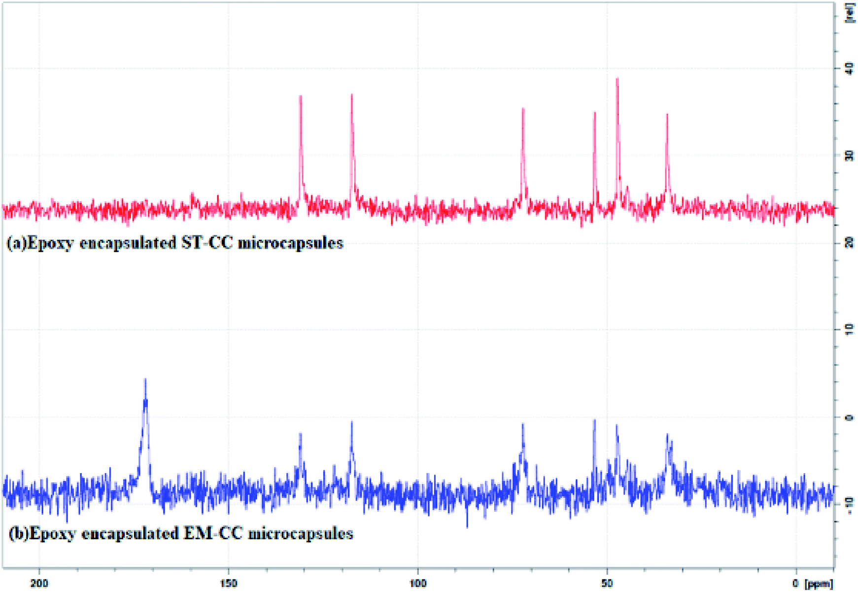 | ||
| Fig. 6 The 13C solid NMR spectra of (a) EPX encapsulated ST-CC microcapsules, and (b) EPX encapsulated EM-CC microcapsules. | ||
Self-healing of EPX composite coatings
Scratch tests were performed on the EPX composite coatings of the metal substrate by varying the loading concentration as 10 wt%, 20 wt%, and 50 wt% with both types of CC microcapsules. The composite coatings were applied on metal substrates to investigate the releasing ability of the loaded CC microcapsules after 24 h of manually fracturing the coatings. As shown in Fig. 7(a), the control specimen associated with the scratch exhibited no signs of release as the depth of the scratch was unchanged. Similarly, none of the EPX/EM-CC coatings exhibited any signs of the apparent release of the healing agent. Indeed, EPX/ST-CC10 also did not show any healing properties. But, EPX/ST-CC20 showed signs of a moderate release of the healing agent (Fig. 7(d)), indicating that the minimal ST-CC loading should be 20 wt% in order to trigger the healing process. Additionally, Fig. 7(b) shows a significant release of the healing agent from EPX/ST-CC 50 composite coating as the scratch was filled up. Once the coating was scratched, the microcapsules along the scratch got damaged, and as a result, the healing agent released into the cavities, thus filling up the gaps. The micrographs of EPX/ST-CC 10 and EPX/EM-CC 10 are given in the ESI (Fig. S5(a and b)†). The release study (stimulating the healing properties) indicated that EPX/ST-CC coatings with 20 wt% or higher CC microcapsules contribute towards self-healing. The ST-CC microcapsules outperformed EM-CC due to (i) less thickness of the shell wall than EM-CC, which was around 650 nm after the heat treatment while that of EM-CC was around 880 nm (Fig. S1(b and c); in ESI†); a thinner wall thickness would allow ST-CC to intrude easily upon crack propagation, (ii) the flake-like rough surface of the ST-CC microcapsules shows higher surface area than EM-CC microcapsules, which will facilitate better interaction with the polymer matrix during composite preparation (when CC microcapsules interact well with the matrix, propagation through the microcapsules should be enhanced), and (iii) the release of EPX through the tiny pores (due to pressure difference at induced stress), apart from the crack intrusion through ST-CC microcapsules, can also be a release mechanism. Despite the high loading capacity of EM-CC (loading contains a fraction of the surfactant), ST-CC showed better performance due to the aforementioned synergistic effects.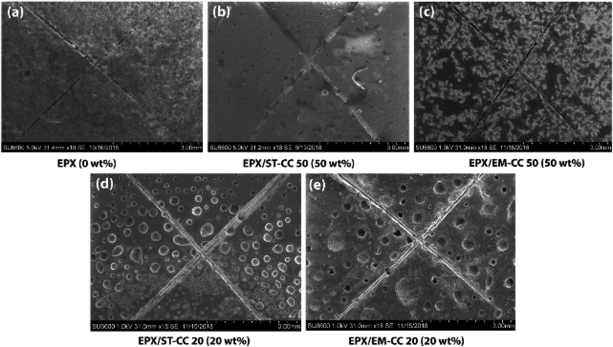 | ||
| Fig. 7 The FE-SEM images of the scratch test on the EPX composite coatings (a) neat [EPX], (b) EPX loaded ST-CC 50 wt% [EPX/ST-CC 50], (c) EPX loaded EM-CC 50 wt% [EPX/EM-CC 50], (d) EPX loaded ST-CC 20 wt% [EPX/ST-CC 20], and (e) EPX loaded EM-CC 20 wt% [EPX/EM-CC 20] after 24 h of scratching, carried out with the help of a sharp object. | ||
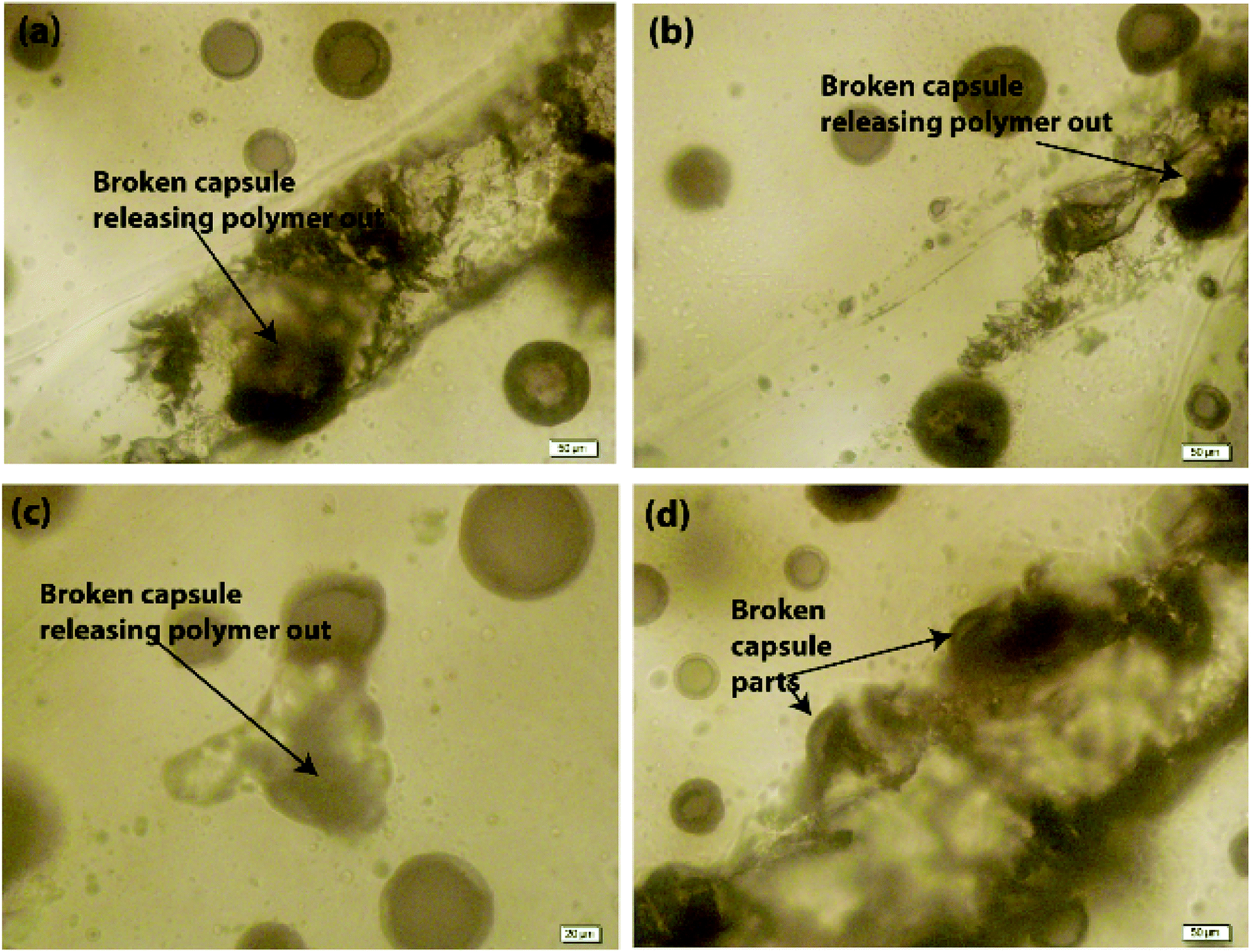
The light microscopy images of EPX/EM-CC10 and EPX/ST-CC10 are illustrated in Fig. 8(a and b), respectively. It shows that both types of microcapsules are well dispersed within the EPX matrix. The light microscopy images of EPX/ST-CC10 and EPX/EM-CC10 composite thin coatings with manually induced cracks exhibit the release of healing agents from the microcapsules (Fig. 9).
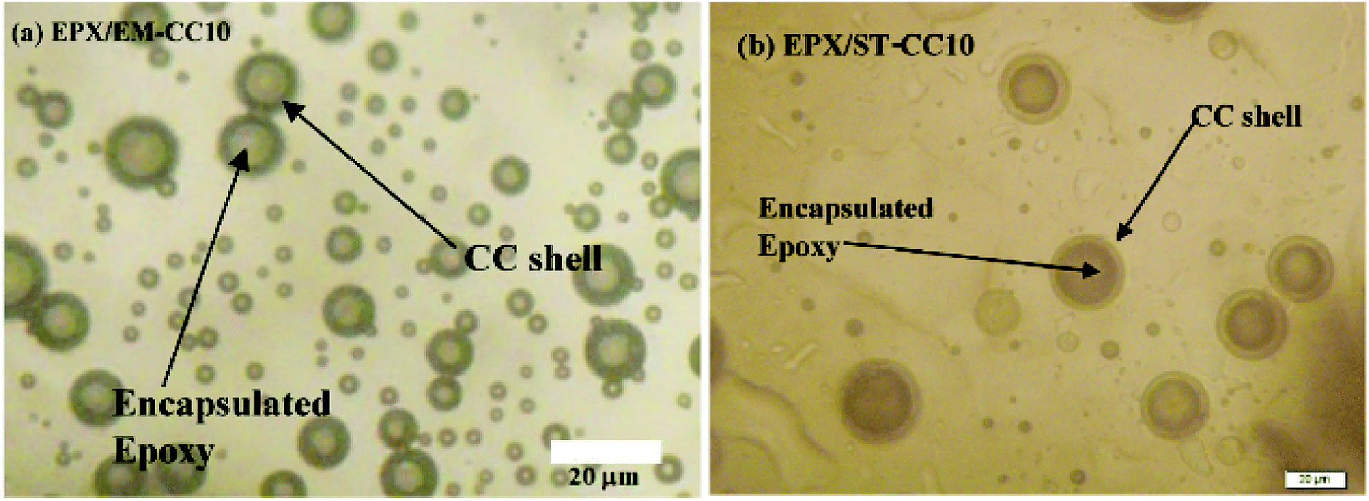 | ||
| Fig. 8 The light microscopy images show a better dispersion of (a) EM-CC microcapsules 10 wt% loaded composite thin coating and (b) ST-CC 10 wt% loaded composite thin coating before scratching. | ||
 | ||
| Fig. 9 The light microscopy images of (a–d) EPX/ST-CC10 with EPX thin composite coating on the glass substrate, thereby confirming the release of the encapsulated EPX after scratching with a sharp object. | ||
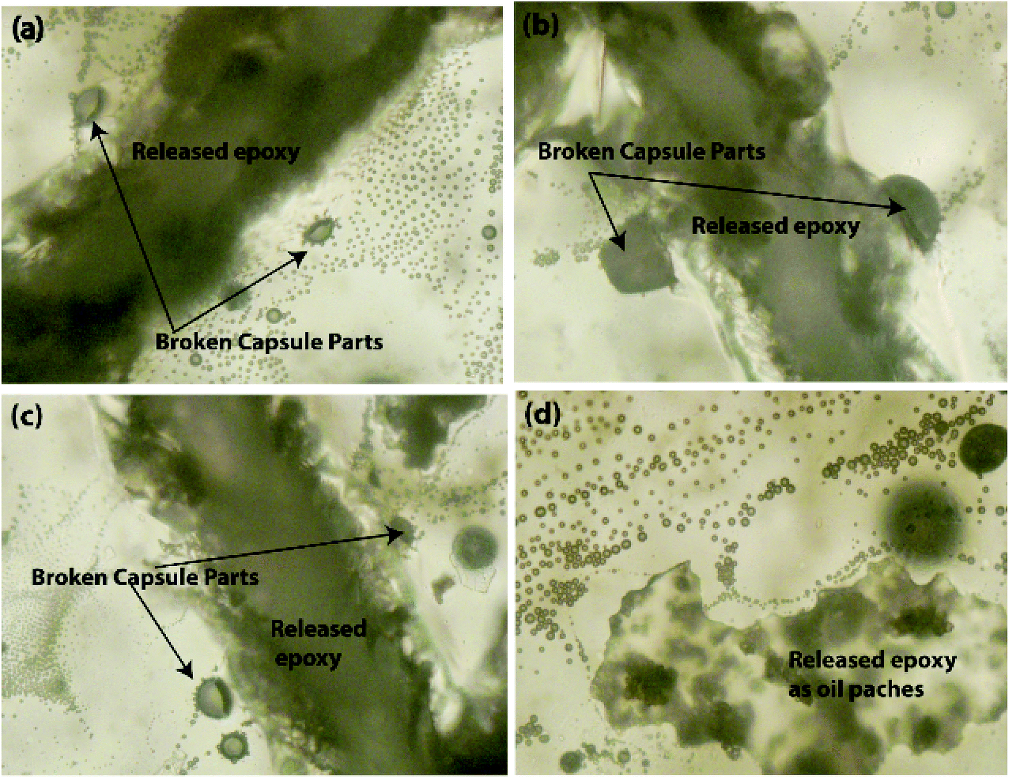
Further, it was observed that the self-healing mechanism of the capsule-based self-healing EPX composite coatings gets triggered upon the intrusion of the microcapsules and releases healing agents into the matrix crack sites. The concept was validated by evaluating EPX/ST-CC10 and EPX/EM-CC10 composite thin-coatings after manually rupturing or scratching the coating surface with a sharp object (Fig. 9 and 10, respectively). Fig. 9(a–d) shows the EPX polymer release from the composite coating of the ST-CC microcapsules. It is evident that the microcapsules were broken along the fracture propagated path (Fig. 9(d) and 10(b)). Fig. 10(a–d) shows the crack propagation in EPX/EM-CC10 composite thin coating, and it was observed that the microcapsules were halved along the crack propagated path to release the healing agent.
 | ||
| Fig. 10 The light microscopy images of (a–c) EPX/EM-CC10 after scratching with a sharp object and (d) after applying a high force on the thin coating with a hammer head (all images were taken under 20 μm resolution). | ||
Additionally, the released EPX patches were also visible as a result of induced mechanical stresses on the thin coatings (Fig. 10(d)). As demonstrated, the encapsulated healing agents in the core of both types of CC microcapsules were released to the crack sites in order to trigger the self-healing process. The optical microscopy images of the scratch test of the composite coatings with other loadings (20 and 50 wt%) are given in the ESI (Fig. S6†).
The ST-CC microcapsules with 50 wt% loading exhibiting a better performance were incorporated into an EPX resin matrix to create a self-healing thin coating, and an accelerated anti-corrosion salt spray test was carried out to evaluate the anti-corrosion performance of the self-healing thin coating. Fig. 11(a and b) show images of the accelerated corrosion test. The scratched area of the metal plate coated with self-healing coating did not show any signs of corrosion compared to the control sample (EPX coating without capsules). This demonstrates the excellent corrosion protection of the prepared self-healing coatings.
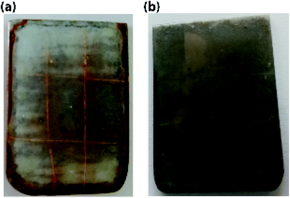 | ||
| Fig. 11 The corrosion test results for metal panels coated with (a) control EPX coating, and (b) EPX coating mixed with 50 wt% of ST-CC microcapsules. 0.1 M NaCl solution was sprayed on the metal plate and kept for 48 h before photography. | ||
Conclusions
The EPX resin encapsulated calcium carbonate spherical microcapsules were successfully fabricated using two methods, namely, the soft-template method and the emulsion method. The sizes of the two types of calcium carbonate microcapsules (EM-CC and ST-CC) were in the range of 2 to 4 μm, with outer shell wall thicknesses of around 600–900 nm. The TGA analysis revealed that the total EPX loading capacity within the ST-CC and EM-CC microcapsules were 11% and 36%, respectively. The FTIR and NMR analysis confirmed the EPX encapsulation and the absence of chemical interactions between EPX and CC microcapsules. Further, the EPX/ST-CC and EPX/EM-CC composite coatings showed the release of the encapsulated healing agents from the microcapsules upon stress intrusion. According to the FE-SEM images, the EPX/ST-CC20 and EPX/ST-CC50 coatings exhibited superior release performance compared to EPX/EM-CC composite coatings. Thus, these formaldehyde-free, non-toxic, biocompatible, and biodegradable CC microcapsules show great potential to be used in self-healing protective coatings, for example, on metal substrates for prolonged protection from corrosion.Conflicts of interest
The authors declare no conflict of interest.Acknowledgements
The authors would like to acknowledge National Research Council, Sri Lanka for supporting this research under grant scheme NRC-17-007 and Dr Nuwan de Silva for his guidance in NMR studies.References
- S. Khoee, S. H. Payandeh, P. Jafarzadeh and H. Asadi, Smart Mater. Struct., 2016, 25, 084014 CrossRef.
- O. Rifaie-Graham, E. A. Apebende, L. K. Bast and N. Bruns, Adv. Mater., 2018, 30, 1705483 CrossRef PubMed.
- D. Y. Wu, S. Meure and D. Solomon, Prog. Polym. Sci., 2008, 33, 479–522 CrossRef CAS.
- I. L. Hia, V. Vahedi and P. Pasbakhsh, Polym. Rev., 2016, 56, 225–261 CrossRef CAS.
- X. Zhou, W. Li, L. Zhu, H. Ye and H. Liu, RSC Adv., 2019, 9, 1782–1791 RSC.
- Y. X. Song, X. J. Ye, M. Z. Rong and M. Q. Zhang, RSC Adv., 2016, 6, 100796–100803 RSC.
- M. Villani, Y. S. Deshmukh, C. Camlibel and A. C. C. Esteves, RSC Adv., 2016, 6, 245–259 RSC.
- S. R. White, N. Sottos, P. Geubelle, J. Moore, M. R. Kessler, S. Sriram, E. Brown and S. Viswanathan, Nature, 2001, 409, 794 CrossRef CAS PubMed.
- V. Vahedi, P. Pasbakhsh, C. S. Piao and C. E. Seng, J. Mater. Chem. A, 2015, 3, 16005–16012 RSC.
- F. Ahangaran, M. Hayaty, A. H. Navarchian, Y. Pei and F. Picchioni, Polym. Test., 2018, 73, 395–403 CrossRef.
- H. Jin, C. L. Mangun, D. S. Stradley, J. S. Moore, N. R. Sottos and S. R. White, Polymer, 2012, 53, 581–587 CrossRef CAS.
- G. L. Li, M. Schenderlein, Y. Men, H. Möhwald and D. G. Shchukin, Adv. Mater. Interfaces, 2014, 1, 1300019 CrossRef.
- Q. Li, N. H. Kim, D. Hui and J. H. Lee, Composites, Part B, 2013, 55, 79–85 CrossRef CAS.
- Y. Yang, Z. Wei, C. Wang and Z. Tong, ACS Appl. Mater. Interfaces, 2013, 5, 2495–2502 CrossRef CAS PubMed.
- E. Koh, N.-K. Kim, J. Shin and Y.-W. Kim, RSC Adv., 2014, 4, 16214–16223 RSC.
- Y. C. Yuan, X. J. Ye, M. Z. Rong, M. Q. Zhang, G. C. Yang and J. Q. Zhao, ACS Appl. Mater. Interfaces, 2011, 3, 4487–4495 CrossRef CAS PubMed.
- Y. Long, B. Vincent, D. York, Z. Zhang and J. A. Preece, Chem. Commun., 2010, 46, 1718–1720 RSC.
- I. L. Hia, P. Pasbakhsh, E.-S. Chan and S.-P. Chai, Sci. Rep., 2016, 6, 34674 CrossRef PubMed.
- G. Nemli and İ. Öztürk, Build. Environ., 2006, 41, 770–774 CrossRef.
- I. L. Hia, E.-S. Chan, S.-P. Chai and P. Pasbakhsh, J. Mater. Chem. A, 2018, 6, 8470–8478 RSC.
- I. L. Hia, W. H. Lam, S.-P. Chai, E.-S. Chan and P. Pasbakhsh, Mater. Chem. Phys., 2018, 215, 69–80 CrossRef CAS.
- H. B. Eral, V. López-Mejías, M. O'Mahony, B. L. Trout, A. S. Myerson and P. S. Doyle, Cryst. Growth Des., 2014, 14, 2073–2082 CrossRef CAS.
- N. Qiu, H. Yin, B. Ji, N. Klauke, A. Glidle, Y. Zhang, H. Song, L. Cai, L. Ma and G. Wang, Mater. Sci. Eng. C, 2012, 32, 2634–2640 CrossRef CAS.
- R. Roth, J. Schoelkopf, J. Huwyler and M. Puchkov, Eur. J. Pharm. Biopharm., 2018, 122, 96–103 CrossRef CAS PubMed.
- W. Wei, G.-H. Ma, G. Hu, D. Yu, T. Mcleish, Z.-G. Su and Z.-Y. Shen, J. Am. Chem. Soc., 2008, 130, 15808–15810 CrossRef CAS PubMed.
- L. Lu, J. Pan and G. Li, J. Mater. Chem. A, 2017, 5, 21505–21513 RSC.
- H. Zhang, X. Zhang, C. Bao, X. Li, D. Sun, F. Duan, K. Friedrich and J. Yang, J. Mater. Chem. A, 2018, 6, 24092–24099 RSC.
- K. Wazarkar, D. Patil, A. Rane, D. Balgude, M. Kathalewar and A. Sabnis, RSC Adv., 2016, 6, 106964–106979 RSC.
- M. Huang and J. Yang, J. Mater. Chem., 2011, 21, 11123–11130 RSC.
- E. Koh, S.-Y. Baek, N.-K. Kim, S. Lee, J. Shin and Y.-W. Kim, New J. Chem., 2014, 38, 4409–4419 RSC.
- A. K. Guin, S. Nayak, M. K. Bhadu, V. Singh and T. K. Rout, ISRN Corros., 2014, 2014, 1–7 CrossRef.
- G. Wu, J. An, D. Sun, X. Tang, Y. Xiang and J. Yang, J. Mater. Chem. A, 2014, 2, 11614–11620 RSC.
- P. D. Tatiya, R. K. Hedaoo, P. P. Mahulikar and V. V. Gite, Ind. Eng. Chem. Res., 2013, 52, 1562–1570 CrossRef CAS.
- A. Vimalanandan, L. P. Lv, T. H. Tran, K. Landfester, D. Crespy and M. Rohwerder, Adv. Mater., 2013, 25, 6980–6984 CrossRef CAS PubMed.
- H. Yi, Y. Yang, X. Gu, J. Huang and C. Wang, J. Mater. Chem. A, 2015, 3, 13749–13757 RSC.
- J. Yamuna, T. Siva, S. S. Kumari and S. Sathiyanarayanan, RSC Adv., 2016, 6, 79–86 RSC.
- A. M. Atta, H. A. Al-Lohedan and K. A. Al-Haddad, RSC Adv., 2016, 6, 41229–41238 RSC.
- D. Sun, H. Zhang, X.-Z. Tang and J. Yang, Polymer, 2016, 91, 33–40 CrossRef CAS.
- M. N. Alizadeh, A. Shayanfar and A. Jouyban, J. Mol. Liq., 2018, 268, 410–414 CrossRef CAS.
- A. I. Petrov, D. V. Volodkin and G. B. Sukhorukov, Biotechnol. Prog., 2005, 21, 918–925 CrossRef CAS.
- D. V. Volodkin, N. I. Larionova and G. B. Sukhorukov, Biomacromolecules, 2004, 5, 1962–1972 CrossRef CAS PubMed.
- G. B. Sukhorukov, D. V. Volodkin, A. M. Günther, A. I. Petrov, D. B. Shenoy and H. Möhwald, J. Mater. Chem., 2004, 14, 2073–2081 RSC.
- P. Zhang and G. Li, Prog. Polym. Sci., 2016, 57, 32–63 CrossRef CAS.
- M. G. González, J. C. Cabanelas and J. Baselga, in Infrared Spectroscopy-Materials Science, Engineering and Technology, InTech, 2012 Search PubMed.
- S. Emami and M. M. A. Nikje, Green Process. Synth., 2019, 8, 108–117 CAS.
Footnote |
| † Electronic supplementary information (ESI) available. See DOI: 10.1039/c9ra03804c |
| This journal is © The Royal Society of Chemistry 2019 |