 Open Access Article
EG/TPU composites with enhanced flame retardancy and mechanical properties prepared by microlayer coextrusion technology
Chao Zhang a,
Meinong Shi*a,
Youchen Zhanga,
Weimin Yanga,
Zhiwei Jiaoa and
Liping Yang*b
aBeijing University of Chemical Technology, Beijing 100029, China. E-mail: shi-mn@mail.buct.edu.cn
bGuangdong Gulf New Materials Institute, Shenzhen 518172, China
First published on 1st August 2019
Abstract
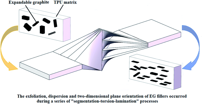
In this work, expandable graphite (EG)/thermoplastic polyurethane (TPU) composites with excellent exfoliation, dispersion and two-dimensional plane orientation of the EG fillers were manufactured by microlayer coextrusion technology. The influence of microlayer coextrusion technology on flame retardancy and mechanical properties of microlayer coextruded composites was investigated. The exfoliation, dispersion and orientation of the EG fillers in TPU matrix were characterized by SEM and XRD. The flame retardancy and thermal stability of the composites were characterized by UL 94, LOI, TGA and CCT. The mechanical properties of the composites were characterized by tensile tests. SEM and XRD showed that microlayer coextrusion technology could not only greatly promote exfoliation and dispersion of the EG fillers in TPU matrix, but also could enhance the two-dimensional plane orientation of the EG fillers in TPU matrix. As compared with the conventional blended composites, the microlayer coextruded composites showed enhanced flame retardancy and mechanical properties, with 15 wt% of EG, the as prepared EG/TPU composites showed a V-0 flame retardance level, whereas EG/TPU composite prepared by conventional blending only showed a V-2 flame retardance level. The exfoliation, dispersion and two-dimensional plane orientation of the EG fillers in TPU matrix were believed to play a critical role in the improvement of flame retardancy. The significance of this research was providing a new feasible idea to fabricate flame retardant composites with excellent mechanical properties.
1. Introduction
As an important commodity plastic, Thermoplastic polyurethane (TPU) is widely used in many applications such as automobiles, sport equipment, medical consumables and food packaging materials, etc.1–4 However, TPU is extremely flammable with melt dripping, and the smoke from combustion and the accompanied release of toxic gases such as HCN and CO greatly restricts its applications in many fields.5 Therefore, more and more researchers have been interested in the flame retardancy modification of TPU.In order to improve the flame retardancy of TPU, all kinds of flame retardants are introduced into TPU to pursue a balanced integration of properties which are required to meet the real needs of industry. Expandable graphite (EG) is an excellent flame retardant for plastic materials. It is non-toxic and does not produce toxic gases when heated. In contact with a heat source, EG expands and produces a large amount of an insulative layer on the surface of the polymer matrix, which can protect the substrate, insulate the heat source and prevent oxygen from coming into contact.6–9 However, as the filler itself, EG has poor interfacial compatibility with the polymer matrix, furthermore, the easy agglomeration of EG also makes the dispersion in the matrix unsatisfactory, both of which greatly affect the final flame retardancy and mechanical properties of the composite materials. Hence, in order to generate enough char contents to inhibit the spread of fire, a large amount of EG filler loading is generally required which conversely causes processing issues and deteriorated mechanical properties.10 For example, in order to achieve a V-0 flame retardance level, it usually requires a high EG loading level up to at least 25%, thus the mechanical properties of the composite will be greatly reduced so that there is little prospect of practical application.11
It is well known that the content of EG fillers satisfying the flame retardancy requirement of the polymer matrix depends on both the chemical structure and the distribution of fillers.12 S. Sánchez-Valdes et al.13 used an amine-alcohol modified polyethylene (PE-g-DMAE) as compatibilizer, and improved the dispersion of IFRs by increasing their compatibility with polymeric matrix. Ming G. et al.14 used expandable graphite (EG) and phosphorus oxychloride to synthesize expanded graphite modified with phosphorus (EGP), and discovered that EGP fillers are more easily dispersed in the FPUF matrix to form a dense carbonization layer compared to EG fillers. Liu L. Z. et al.15 load the boric acid on the surface of expandable graphite (EG), and discovered that the modification of EG fillers could promote the increase of carbonization layer density. Li J. et al.16 and Liu D. Y. et al.17 investigated the synergy between different flame retardants by adding two or three flame retardancy components into the polymer matrix, and discovered that the strong interfacial bonding between these different char residues strengthened the integrality and continuity of the intumescent carbonization layers, leading to a stronger barrier effect in condensed phase. The above methods are undoubtedly very effective for preparing flame retardant composites with high mechanical properties, and lays a foundation for the development of high performance flame retardant composites.
Recently, microlayer coextrusion technology has been innovatively used to prepare flame retardancy composites. Laufer G. et al.,18 Li Y. et al.,19 and Carosio F. et al.20 found that the multilayered coating could effectively prolong the time to ignition and reduce the heat release rate of polymeric substrates. Chen B. S. et al.21 investigated the influence of the multilayered distributing state of IFRs on the flame-retarding properties of the matrix and found that the layer interfaces and confined layer spaces in the multilayered system were considered to play a crucial role in retarding the spread of fire as well as the propagation of crazes. However, few studies related to the influence of the exfoliation, dispersion and orientation of fillers on the flame retardancy of the polymer matrix are concerned, to the authors' best knowledge. As compared with conventional blended composites, microlayer coextruded composites have alternating layered structures that are continuous along the extrusion direction, while the extruded film has thousands of layers in the case of constant thickness and the single layer thickness can be up to nanometer scale.22 As seen in Fig. 1, during the microlayer coextrusion process, this unique cavity structure causes the composite melt to be constantly subjected to a force that gradually widens and narrows, which is very similar to the effect of biaxial stretching. This distinctive processing technology will be very beneficial to the exfoliation, dispersion and two-dimensional plane orientation of the filler in polymer matrix, which will greatly promote the increase of carbonization layer density during combustion. It is well known that the carbon layer plays an important role of heat insulation and oxygen barrier during the combustion process, and the change in carbon layer density will significantly affect the flame retardancy of the whole composites. Simultaneously, this unique multilayer structure can effectively inhibit the propagation and extension of cracks. Sung et al.23,24 investigated the mechanical behaviors of alternating multilayer composite consisting of polycarbonate (PC) and styrene–acrylonitrile copolymer (SAN) layers and found that the crazes generated from SAN layers could be terminated by shear bands in adjacent PC layers through interfacial adhesion effect, resulting in the increase of the strength and toughness of the whole composite. Therefore, microlayer coextrusion technology has great application prospects in manufacturing flame retardancy composites with balanced mechanical properties.
In this paper, the EG/TPU microlayer coextruded composites were prepared by microlayer coextrusion technology. The effect of the exfoliation, dispersion and orientation of the EG fillers in TPU matrix on the flame retardancy of the whole composite was investigated. At the same time, the enhancement effect of the microlayer coextrusion technology on the mechanical properties of the composite was also investigated to evaluate the feasibility of fabricating the flame retardancy microlayer coextruded composites with balanced mechanical properties.
2. Experimental
2.1. Materials
TPU (69M92), with a density of 1.22 g cm−3 and hardness of 92 Shore A, was provided by Baoding Bangtai Polymer New Material Co. (China). EG, with a mean particle size of about 270 mesh, were supplied by Qingdao Kangboer Graphite Products Co., Ltd. (China).2.2. Sample preparation
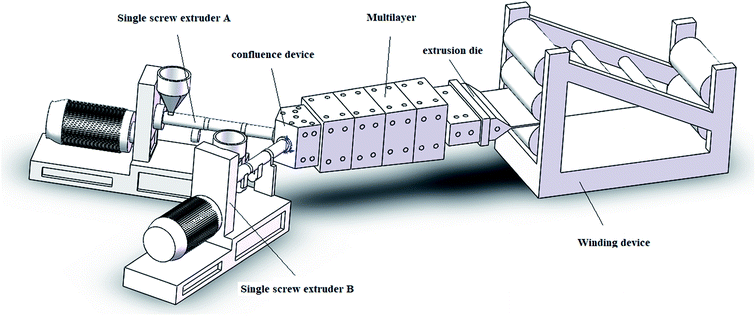
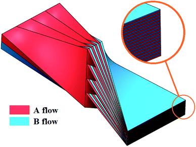
Prior to the microlayer coextrusion process, the EG/TPU pellets with different amounts of EG were prepared using a twin screw extruder. Set temperatures from hopper to die were 170, 185, 195, and 190 °C, respectively. The screw speed of the twin screw extruder was 300 rpm.During the microlayer coextrusion process, EG/TPU pellets were added into extruders A and B to finally obtain the 512 layers of EG/TPU microlayer coextruded multilayer film. As seen in Fig. 2, the microlayer coextrusion equipment mainly consists of two single screw extruders, a confluence device, four multipliers, an extrusion die and a winding device. The single screw extruders are combined in a confluence device, to obtain a 2-layers polymer melt. The 2-layers melt flowing into the first multiplier was divided into four equal parts in the width direction, as shown in Fig. 3. The four equal parts were twisted by 90°, and then flowed through the second multiplier, and the total thickness and width of the melt at the outlet were equal to the inlet. Each time a multiplier was passed, the number of layers of the melt was increased by a factor of four and the thickness was correspondingly reduced by a factor of four. When the melt flowed through four multilayers, the number of layers turned into 512. The set temperature from the feed hopper to the die were 170, 185, 195, and 190 °C, respectively, and the set temperature of the multiplier was 190 °C. The screw speed of the single screw extruder was 300 rpm.
For the comparison with microlayer coextruded composites, the EG/TPU conventional blended monolayer film was also prepared using only one extruder of the microlayer coextrusion equipment without any multilayers.
The formulations of different samples are shown in Table 1.
| Samples | Sample serial number | EG content |
|---|---|---|
| Conventional blended composites (1 layer) | CB-0 | 0% |
| CB-5 | 5% | |
| CB-10 | 10% | |
| CB-15 | 15% | |
| Microlayer coextruded composites (512 layers) | MC-0 | 0% |
| MC-5 | 5% | |
| MC-10 | 10% | |
| MC-15 | 15% |
2.3. Morphological observation
Scanning electron microscopy (SEM, Hitachi, S-4700) was used to investigated the morphology of the conventional blended and microlayer coextruded composites. All these samples were quenched in liquid nitrogen for 1 h and then were cryogenically fractured. The fractured sections were sputter coated with Au and then observed.2.4. X-ray diffraction spectroscopy (XRD) analysis
X-ray diffraction spectroscopy (XRD, Rigaku, 2500VB2) was used to investigated the dispersibility of EG filler in the TPU matrix. All samples were scanned under 2θ ranging from 0.5 to 35° at a rate of 1° min−1.2.5. Combustion tests
LOI values were measured using the oxygen index measuring instrument (China, JF-4TG) on test bars of 130 × 6.5 × 2 mm3 in size, according to GB/T 2406.2-2009. Measurements were made on at least 15 specimens of each sample.Vertical burning tests (UL 94) were also conducted using the vertical burning tester (China, HVR-JT/M) on the test bars of 130 × 13 × 2 mm3 according to ASTM D3801. Measurements were made on at least 5 specimens of each sample.
2.6. Thermal stability analysis
All thermogravimetric tests were performed on a thermogravimetric analyzer (TGA, Waters Corporation, TGAQ50). Each sample, with a weight of about 5 mg, was heated from 30 °C to 800 °C at a rate of 10 °C min−1 under nitrogen flow of 60 ml min−1.2.7. Cone calorimeter tests
Cone calorimeter tests were performed using the cone calorimeter (TESTech Instrument (Suzhou) Technologies, TTech-GBT16172) according to ISO5660-1 2015 under an external heat flux of 50 kW m−2. The sample size for the cone calorimeter tests was 100 × 100 × 3 mm3. For each sample, average value of at least 3 specimens was taken as the final test results.2.8. Mechanical properties
Tensile tests were performed using universal testing machine (Instron, Instron 3367) according to GB/T 1040.3-2006. Measurements were made on at least 5 specimens of each sample at a test speed of 100 mm min−1.3. Results and discussion
3.1. Phase morphology
Many studies have proven that the microlayer coextrusion technology not only provide high enough shear stress to make the 2-D filler with high aspect ratio orientated along a two-dimensional plane in the polymer matrix, but also enhance the exfoliation and dispersion of fillers.25–29 Thus we believe that both the exfoliation, dispersion and two-dimensional plane orientation of EG fillers could be promoted in TPU matrix by microlayer coextrusion technology.SEM was used to analyze EG orientation and dispersion. Fig. 4 shows the fracture surface of the EG/TPU samples. The fracture surfaces of conventional blended composites and microlayer coextruded composites with 5, 10 and 15 wt% of EG are shown in Fig. 4. The large EG aggregates are found in the conventional blended composites with 5, 10 and 15 wt% of EG. The higher the content of EG fillers in conventional blended composites, the larger aggregates. Upon the introduction of microlayer coextrusion technology, it could be observed that most of the large EG aggregates were broken into thinner flakes during the microlayer coextrusion process. There is much lesser large EG aggregates in microlayer coextruded composites with 5, 10 and 15 wt% of EG. Possibly the microlayer coextrusion technology could greatly promote the exfoliation and dispersion of the EG fillers in the TPU matrix. Furthermore, the two-dimensional plane orientation of the EG fillers in the composites could be enhanced by microlayer coextrusion technology. As shown in Fig. 4a2, b2 and c2, it can be found that most of large EG aggregates are randomly dispersed in conventional blended composites. From Fig. 4d2, e2 and f2 we can see that more and more EG aggregates delaminated into thin flakes and these thin flakes aligned parallel to a two-dimensional plane in microlayer coextruded composites under the action of the force field in the multilayers.
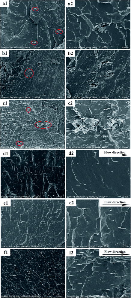 | ||
| Fig. 4 SEM images of the brittle fracture surface of (a1, a2) CB-5, (b1, b2) CB-10, (c1, c2) CB-15, (d1, d2) MC-5, (e1, e2) MC-10, (f1, f2) MC-15. | ||
3.2. XRD analysis of expandable graphite (EG)
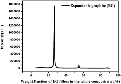
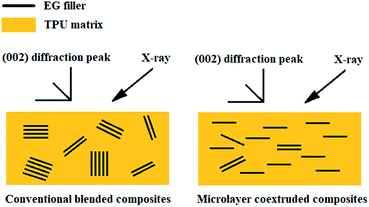
XRD analysis of CB-5, MC-5, CB-10, MC-10, CB-15 and MC-15 are performed, as shown in Fig. 6, all the EG/TPU composites showed the same characteristic diffraction peak (002) of EG at about 26.4° (Fig. 5). The angle (both around 26.4°) of the (002) diffraction peak of the microlayer coextruded composite is very similar to that of the conventional blended composite, which indicates that the interlayer spacing of the EG filler was not changed during the microlayer coextrusion process. Furthermore, it can also be found that the (002) diffraction peaks of the microlayer coextruded composites are apparently stronger than that of the conventional blended composites, and shows a very sharp diffraction peak in Fig. 6. From Fig. 4 we can see that the microlayer coextrusion technology can greatly facilitate the exfoliation, dispersion and two-dimensional plane orientation of the EG fillers in the TPU matrix, and the enhanced peak value of the (002) diffraction peak can be explained by the changing state of EG fillers. It has been demonstrated that the orientation and exfoliation of graphite can significantly affect the peak value of the (002) characteristic diffraction peak. The better the orientation of graphite in the polymer matrix, the XRD pattern in the direction perpendicular to the orientation of the graphite will show larger and sharper peak value at 2θ = 26.4°.30,31 The EG fillers undergo a continuous exfoliation process during the microlayer coextrusion process, and the EG fillers after exfoliation are gradually oriented along the two-dimensional plane under the force of a biaxial stretching inside the cavity, which endows the EG fillers with a highly oriented structure along the (002) crystal plane. Besides, the number of carbon layers arranged in parallel is large, and the degree of regularization is high (seen in Fig. 7). Furthermore, the integrated peak value of the (002) diffraction peak of the whole composite exhibits a significant increase, and the results measured by XRD can support the two-dimensional plane orientation of the EG filler in the TPU matrix, which is consistent with the SEM results.3.3. Flame retardancy effect
| Sample | t1/s | t2/s | Cotton indicator ignited by flaming particles or drops | Afterflame or afterglow of any specimen up to the holding clamp | Vertical burning level |
|---|---|---|---|---|---|
| CB-0 | 17.2 | — | Yes | Yes | NR |
| CB-5 | 15.1 | 15.7 | Yes | Yes | NR |
| CB-10 | 12.5 | 13.8 | Yes | Yes | NR |
| CB-15 | 8.1 | 10.2 | Yes | No | V-2 |
| MC-0 | 16.7 | — | Yes | Yes | NR |
| MC-5 | 6.1 | 8.2 | Yes | Yes | NR |
| MC-10 | 3.4 | 3.2 | Yes | No | V-2 |
| MC-15 | 2.8 | 3.2 | No | No | V-0 |
Different flame formations could be observed for TPU matrix in Table 2: the dripping flame phenomenon was observed for pure TPU prepared by both conventional blended technology and microlayer coextrusion technology, the dripping appears at once with a release of burning drops that burned the cotton within the first few seconds of ignition, and finally all the samples were totally burned out. Thus pure TPU prepared by both conventional blended technology and microlayer coextrusion technology did not pass the UL-94 tests.
For the EG/TPU composites prepared by conventional blended technology, both the afterflame time t1 and t2 of the composite will be reduced gradually with the increase of EG content, thereby improving the flame retardancy of the composite. As the EG filler content increased to 15 wt%, the afterflame time t1 and t2 of the EG/TPU conventional blended composites decreased to 8.1 s and 10.2 s respectively, accompanied by drops and the afterflame lower than the 125 mm mark, reaching a V-2 rating. Therefore, we found that the drop phenomenon is the main factor to descend the vertical burning level of EG/TPU composites.
Compared with conventional blended technology, the EG/TPU composite prepared by the microlayer coextrusion technology has apparently enhanced flame retardancy in the case of the same EG filler content. TPU composite with only 10 wt% of EG can reach a V-2 rating. The TPU composite with 15 wt% of EG did not show drop phenomenon in combustion, resulting in a V-0 rating, while the composite with the same EG content prepared by conventional blended technology only reaches a V-2 level.
It is well known that the EG filler will expand to form an expansion layer on the surface of the composite material under heating, and then the expansion layer is used as a barrier layer to isolate oxygen and heat. Therefore, the enhanced exfoliation, dispersion and two-dimensional plane orientation of the EG filler in the TPU matrix has a great influence on the density of the expansion layer, thereby affecting the flame retardancy of the composite material. The EG/TPU composite prepared by conventional blended technology will form a poor density expansion layer under high temperature combustion due to the poor dispersion of the EG filler. And this results in the first occurrence of combustion in the lower density region of the expansion layer, greatly increasing the possibility of drop phenomenon, thereby reducing the flame retardancy of the composite. However, compared with the conventional blended technology, the EG/TPU composites prepared by microlayer coextrusion technology has better exfoliation, dispersion and two-dimensional orientation of the EG fillers, and the uniformly dispersed EG rapidly expands to form a dense expansion layer under high temperature combustion, thereby greatly improved the flame retardancy of the composite material.
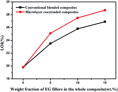
It can be seen from Fig. 8 that the LOI value of pure TPU by both conventional blended technology and microlayer coextrusion technology are similar (both around 19.8%). The LOI value of the TPU with 5 wt%, 10 wt% and 15 wt% of EG prepared by conventional blended technology is 23.5%, 25.8% and 26.9% respectively. Compared with conventional blended technology, the EG/TPU composite prepared by microlayer coextrusion technology have higher LOI value at the same EG filler content. The LOI value of the TPU with 5 wt%, 10 wt% and 15 wt% of EG prepared by microlayer coextrusion technology is 25.1%, 27.5% and 28.7% respectively. Thus, it could be concluded that with the increase of the EG filler content, the flame retardancy of the EG/TPU composite increased obviously. Furthermore, compared with conventional blended technology, microlayer coextrusion technology is more conducive to improving the flame retardancy of EG/TPU composite. van Krevelen et al.32 found that the formation of chars can inhibit the release of flammable carbonaceous gases, and reduce the exothermicity induced by pyrolysis reactions. Hence, a higher density of the expansion layer should be followed with a higher LOI value. Both the exfoliation, dispersion and two-dimensional plane orientation of EG fillers could be improved by microlayer coextrusion technology. This will increase the density of the expansion layer of the composite under high temperature combustion, and thereby improving the flame retardancy properties of the composite.
3.4. Thermal stability
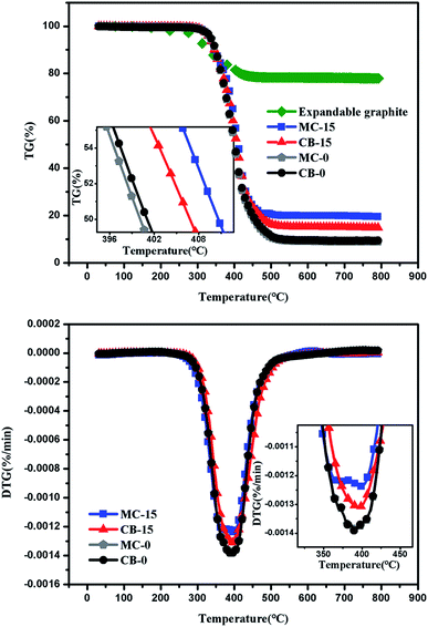
Thermal properties of EG/TPU composites are investigated by TGA under nitrogen atmosphere. TGA data of EG/TPU composites are given in Table 3. The related TGA curves are shown in Fig. 9. In this section, TPU composites with 0 wt% and 15 wt% of EG prepared by both conventional blended technology and microlayer coextrusion technology were tested by thermogravimetric analysis. The onset decomposition temperature (T5%) were defined as the temperature at which the weight loss reached 5%. The char residue and temperature of the maximum weight loss rate (Tmax) of the samples were obtained from the DTG curves.| Sample | T5%/°C | T50%/°C | Tmax/°C | Char residue at 800 °C/% |
|---|---|---|---|---|
| CB-0 | 335.92 | 398.95 | 397.25 | 6.44 |
| MC-0 | 336.02 | 398.97 | 397.87 | 6.74 |
| CB-15 | 333.21 | 405.87 | 401.25 | 15.35 |
| MC-15 | 332.87 | 410.71 | 407.22 | 19.53 |
Firstly, the thermal stability of EG fillers were tested by TGA to better investigate the TGA results of EG/TPU composites. It can be seen from the EG curve in Fig. 9 that the intercalant in the EG began to decompose at around 180 °C degrees and decomposed rapidly at 270–400 °C. The processing temperature of the EG/TPU composite in this experiment was between 170 °C and 190 °C. Hence, it can be concluded that only little amount of intercalant in the EG de-intercalated from the EG in the extrusion process.
It can be seen from Fig. 9 and Table 3 that the decomposition temperature at 5% and 50% weight loss (T5% and T50%) for sample CB-0 is 335.92 °C and 398.95 °C respectively, Tmax where the composites show the maximum mass loss is 397.25 °C. At last the char residue of sample CB-0 arrives at 6.44%. For the sample MC-0, there is little difference between MC-0 and CB-0, thus MC-O and CB-0 show approximately one curve on TG and DTG images. It can be found that the thermal performance of pure TPU can be hardly influenced by microlayer coextrusion technology.
Compared with pure TPU, the starting decomposition temperature at 5% (T5%) for both samples CB-15 and MC-15 is lower. The apparent decrease could be mainly explained that the intercalant in EG would decompose rapidly at 270–400 °C to release volatiles such as sulfur dioxide and water, which would result in a loss of quality in the EG/TPU composite, and thereby reducing the T5% temperature of the EG/TPU composite.
Furthermore, the T50% and Tmax temperature for sample CB-15 is 405.87 °C and 401.25 °C respectively, which is higher than that of pure TPU. At the same time, the char residue at 800 °C increase by 138.35% over pure TPU. The apparent increase could be mainly explained that the addition of EG filler may benefit for the formation of the expansion layer of the composite under high temperature combustion. However, The T50% and Tmax temperature for sample MC-15 is 410.71 °C and 407.22 °C respectively, which is significantly higher than that of both CB-15 and pure TPU. At the same time, the char residue at 800 °C increase by 203.26% and 27.2% over CB-15 and pure TPU respectively. This indicates that microlayer coextrusion technology is more conducive to improving the thermal stability of EG/TPU composite than conventional blended technology. This can be explained by the fact that the microlayer coextrusion technology not only promotes the two-dimensional plane orientation of the EG filler, but also greatly enhances its exfoliation and dispersion in TPU matrix, which will greatly improve the formation of the expansion layer of the composite under high temperature combustion, thereby greatly improving the thermal stability of the composite. Improvement in thermal performance will contribute to the development of composite with better integrated properties.
3.5. Cone microcalorimetry
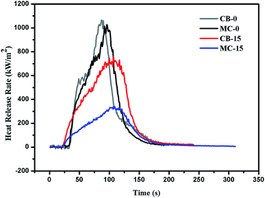
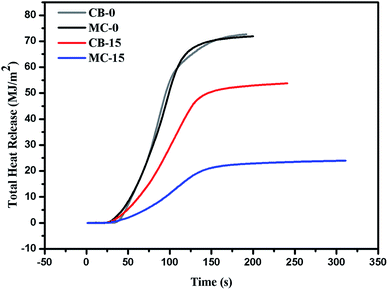
The experimental results obtained by the cone calorimeter have a good correlation with the large combustion experiments, and thus are widely used in the flame retardant research of polymer materials. According to our test results, The TPU microlayer coextruded composite with 15% of EG had the best flame retardancy all samples, so in this section, TPU composites with 0 wt% and 15 wt% of EG prepared by both conventional blended technology were tested by cone calorimeter. The heat release rate (HRR) and the total heat release (THR) curves of samples CB-0, MC-0, CB-15, MC-15 were shown in Fig. 10 and 11, and the corresponding data were shown in Table 4.| Sample | TTI (s) | PHRR (kW m−2) | Av-HRR (kW m−2) | THR (MJ m−2) | TSR (m2 m−2) | Char yields (%) |
|---|---|---|---|---|---|---|
| CB-0 | 36 | 1065 | 149.17 | 72.63 | 1018 | 7.92 |
| MC-0 | 35 | 1028 | 144.88 | 71.93 | 1097 | 8.27 |
| CB-15 | 29 | 759 | 121.33 | 53.82 | 761 | 16.42 |
| MC-15 | 28 | 361 | 100.79 | 23.99 | 357 | 21.58 |
As seen in Fig. 10, 11 and Table 4, there is little difference in the cone calorimetry data between CB-0 and MC-0, which indicates the flame retardancy of pure TPU can be hardly influenced by microlayer coextrusion technology.
Time to ignition (TTI) is usually an important parameter for evaluating the combustion properties of polymer materials. As seen in Table 4, Compared to pure TPU, the addition of EG causes an apparent decrease (from 36 s to 29 s) in the TTI value of the composite. It can be explained that the reduction in TTI arises from the black color of EG which causes the increased radiant heat absorption within the top layer of the material.33–35 In addition, it can be found that the microlayer coextrusion technology has little effect on the time to ignition of EG/TPU composites.
Both HRR and THR are important parameters for flame retardancy evaluation. It can be seen clearly from Fig. 10 and 11 that very big differences of combustion behaviors exist between the TPU composites with the same EG content under different processing technologies. EG is an effective flame retardant and the incorporation of it by conventional blended technology could decrease the HRR and THR values of the TPU to some extent. The addition of EG promoted the formation of a carbon layer to a certain extent during combustion, and the carbon layer acted as a barrier layer to limit the heat and mass transfer from polymer to the heat source during combustion. When prepared by microlayer coextrusion technology, the decreases in these values are more significant, especially the HRR and THR values, which were decreased by 59% (from 1046 kW m−2 to 431 kW m−2) and 67% (from 72.63 MJ m−2 to 23.99 MJ m−2), respectively. Furthermore, MC-15 (21.58%) left much more carbon residues than CB-15 (16.42%) under the condition that the EG filler content is constant. It can be discovered that microlayer coextrusion technology could endow EG system with higher flame retardant efficiency compared to conventional blended technology. It can be explained by changes in exfoliation, dispersion and orientation of the EG fillers in TPU matrix. Microlayer coextrusion technology could not only greatly promote exfoliation and dispersion of the EG fillers in TPU matrix, but also could enhance the two-dimensional plane orientation of the EG fillers in TPU matrix. The good exfoliation and dispersion of the EG fillers in TPU matrix could greatly facilitate the formation of the carbon layer in the early stages of combustion, and it could also greatly increase the density of the carbon layer during combustion. Carbon layers generated during combustion act as a barrier for both heat flow and mass transport, thereby improving the flame retardancy of the TPU composites.
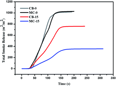
Suffocation caused by smoke is one of the main causes of death from the real fire, therefore the TSR changes of EG/TPU composites are also investigated during combustion. As seen in Fig. 12 and Table 4, the TSR value of CB-15 decreased by 29% (from 1065 m2 m−2 to 759 m2 m−2) compared with that of pure TPU. In addition, when prepared by microlayer coextrusion technology, the decreases in TSR value is more significant, which is decreased by 66% (from 1065 kW m−2 to 461 kW m−2) compared with that of pure TPU. It is well know that EG can promote the TPU matrix to produce a protective barrier layer to effectively prevent smoke generation. The microlayer coextrusion technology can promote the exfoliation, dispersion and two-dimensional plane orientation of the EG fillers in TPU matrix, which is very beneficial to the formation of carbon layer during combustion and can further generate a more compact carbon layer, which will greatly help to block the production of smoke during combustion.
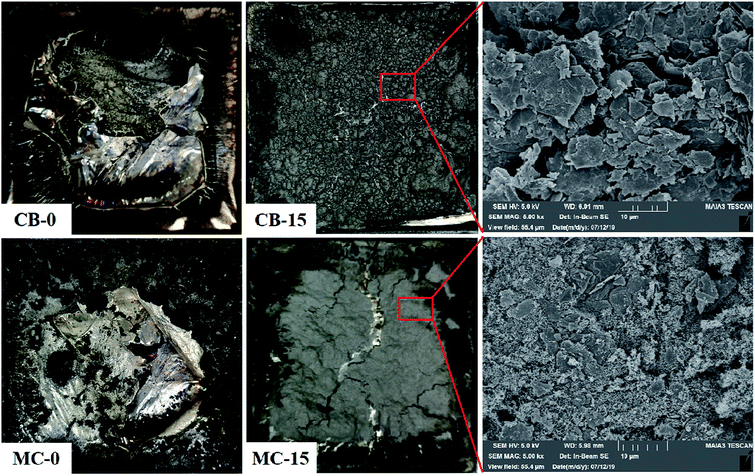
The microscopic morphology of the char residues after the CCT were examined by SEM in order to better understand the carbon layer formation effects of flame retardant TPU with EG fillers after combustion. As seen in Fig. 13 (CB-0 and MC-0), there is little char residues from pure TPU prepared by both conventional blended technology and microlayer coextrusion technology after combustion due to its inflammability, which indicates the flame retardancy of pure TPU can be hardly influenced by microlayer coextrusion technology. In the case of the EG/TPU composites prepared by conventional blended technology (Fig. 13, CB-15), its char residues can form loose carbon layer structures with small holes. The carbon layer structures act as a barrier for both heat flow and mass transport during combustion, thereby improving the flame retardancy of the TPU composites. However, the small holes could provide a flow channel for the flammable gas from the inner matrix to the gas phase. Hence, the char residues of sample CB-15 could only exhibit the limited flame retardancy. For the EG/TPU composites prepared by microlayer coextrusion technology (Fig. 13, MC-15), its char residues can form flat and tight carbon layer structures with no holes. Obviously, EG/TPU composites prepared by microlayer coextrusion technology can form a denser carbon layer structure compared to conventional blended technology, which is attributed to the excellent dispersion, exfoliation and orientation of the EG fillers in TPU matrix. Hence, the EG/TPU composites prepared by microlayer coextrusion technology can exhibit much better flame retardancy compared to conventional blending technology.
3.6. Mechanical properties
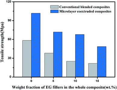
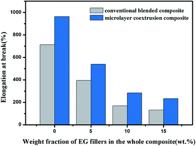
In addition to flame retardancy of composites, mechanical properties are also indispensable for practical application. Although the addition of fillers can improve the flame retardancy of the composites, it probably also greatly deteriorate the mechanical properties of the materials due to the promoted cracks spread in polymer matrix induced by fillers.36,37 It has been confirmed that the microlayer coextrusion technology can greatly alleviate the negative effect of the deteriorate in the mechanical properties of the composites due to the addition of the filler.38,39 Therefore, in this work, tensile tests are performed to investigate the influence of EG filler orientation and dispersion on the tensile strength and elongation at break of TPU composites. As shown in Fig. 14 and 15, the tensile strength and elongation of break of conventional blended composites are dramatically decreased with the addition of EG fillers. This can be explained by the fact that the large EG aggregates which are randomly distributed in the conventional blended composites, act as stress concentrations in the TPU matrix, provided potential development areas for cracks generation and accelerated the propagation of cracks throughout the whole EG/TPU composite.From Fig. 14 and 15, it can be also found that the tensile strength and elongation at break of microlayer coextruded composites shows significant improvement as compared with that of conventional blended composites. The tensile strength and elongation at break of the microlayer coextruded composites with 15 wt% of EG increased by 123% and 85% respectively, compared to conventional blended composites with 15 wt% of EG. For pure polymers, the unique interfacial effects produced by the microlayer coextrusion technology will facilitate the two-dimensional plane orientation of the pure polymer molecular chains at the microlayer interface, which will greatly improve the mechanical properties of the material along the two-dimensional plane orientation.40,41 Hence, the mechanical properties of pure TPU prepared by microlayer coextrusion technology are much better, compared to the pure TPU conventional blended composites. The enhancement of the mechanical properties of microlayer coextruded composites with EG fillers loading could be explained in two ways. On the one hand, large EG aggregates may have some defects which could be broken easily, also, the interfacial interaction between EG and TPU should also be considered, for thin flakes, there's larger interfacial surface of the thin fillers, whereas for large EG aggregates, the interfacial surface is much lower, which will lead to poor interfacial interactions. Poor interfacial interactions between EG fillers and TPU matrix will provide the possibility of crack growth and accelerate the extension of cracks throughout the entire composite, which is very detrimental to the mechanical properties of the composite. The gradual exfoliation of large EG aggregates during the microlayer coextrusion process will greatly improve the interface surface between EG and TPU, which can decrease the stress concentration effect of the EG in the microlayer coextruded composites. On the other hand, the fracture mechanism of microlayer coextruded composites is different from that of conventional blended composites. It has been confirmed that during the deformation of the microlayer coextrusion composites under stress, the cracks initiated in brittle layers will be terminated by the adjacent ductile layers.42 This indicates that the microlayer coextrusion technology may provide a potential method to manufacture flame retardancy composites with balanced mechanical properties.
4. Conclusion
The EG/TPU composites with excellent exfoliation, dispersion and two-dimensional plane orientation of the EG fillers were prepared by microlayer coextrusion technology. Compared to conventional blended composites, the microlayer coextruded composites showed apparently enhanced flame retardancy and mechanical properties. The force field in multilayers during the microlayer coextrusion process could greatly enhance the exfoliation, dispersion and two-dimensional plane orientation of the EG fillers. It not only enables the large EG aggregates break into thin flakes, but also promotes a more uniform distribution of the EG filler in the TPU matrix, which can significantly improve the density of the expansion layer during the burning process and thereby enhance the flame retardancy of the whole composite. Furthermore, the microlayer coextruded composites showed higher tensile strength and elongation at break compared to that of conventional blended composites. Therefore, it can be concluded that the microlayer coextrusion technology may provide a potential approach to manufacture flame retardancy polymer composites with balanced mechanical properties.Conflicts of interest
There are no conflicts to declare.Acknowledgements
This work is supported by the National Key Research and Development Plan of China (No. 2016YFB0302000), the Guangdong Provincial Science and Technology Plan Projects (Grant No. 2016B090915001).References
- A. Toldy, G. Harakály, B. Szolnoki, E. Zimonyi and G. Marosi, Flame retardancy of thermoplastics polyurethanes, Polym. Degrad. Stab., 2012, 97, 2524–2530 CrossRef CAS.
- D. Tabuani, F. Bellucci, A. Terenzi and G. Camino, Flame retarded thermoplastic polyurethane (TPU) for cable jacketing application, Polym. Degrad. Stab., 2012, 97(12), 2594–2601 CrossRef CAS.
- A. Toldy, G. Harakály, B. Szolnoki, E. Zimonyi and G. Marosi, Flame retardancy of thermoplastics polyurethanes, Polym. Degrad. Stab., 2012, 97(12), 2524–2530 CrossRef CAS.
- U. Almeida Pinto, L. L. Y. Visconte, J. Gallo and R. C. R. Nunes, Flame retardancy in thermoplastic polyurethane elastomers (TPU) with mica and aluminum trihydrate (ATH), Polym. Degrad. Stab., 2000, 69(3), 257–260 CrossRef.
- H. Li, N. Ning, L. Zhang, Y. Wang, W. Liang and M. Tian, Different flame retardancy effects and mechanisms of aluminium phosphinate in PPO, TPU and PP, Polym. Degrad. Stab., 2014, 105(7), 86–95 CrossRef CAS.
- Z. Zong Min, R. Wen-Hui, K. A-Hui, L. Wang and W. Yu-Zhong, Highly effective flame retarded polystyrene by synergistic effects between expandable graphite and aluminum hypophosphite, Polym. Degrad. Stab., 2018, 154, 1–9 CrossRef.
- L. J. Li, Y. J. Chen, L. J. Qian, B. Xu and W. Xi, Addition flame-retardant effect of nonreactive phosphonate and expandable graphite in rigid polyurethane foams, J. Appl. Polym. Sci., 2018, 135(10), 45960 CrossRef.
- R. Wen-Hui, L. Wang, H. Wang, H. B. Zhao and Y. Z. Wang, Flame-retardant and smoke-suppressant flexible polyurethane foams based on reactive phosphorus-containing polyol and expandable graphite, J. Hazard. Mater., 2018, 360, 651–660 CrossRef PubMed.
- D. Y. Liu, B. Zhao, J. S. Wang, P. W. Liu and Y. Q. Liu, Flame retardation and thermal stability of novel phosphoramide/expandable graphite in rigid polyurethane foam, J. Appl. Polym. Sci., 2018, 135(27), 46434 CrossRef.
- P. Kiliaris and C. D. Papaspyrides, Polymer/layered silicate (clay) nanocomposites: an overview of flame retardancy, Prog. Polym. Sci., 2010, 35(7), 902–958 CrossRef CAS.
- L. A. Savas, T. K. Deniz, U. Tayfun and M. Dogan, Effect of microcapsulated red phosphorus on flame retardant, thermal and mechanical properties of thermoplastic polyurethane composites filled with huntite & hydromagnesite mineral, Polym. Degrad. Stab., 2017, 135, 121–129 CrossRef CAS.
- F. Laoutid, L. Bonnaud and M. Alexandre, et al., New prospects in flame retardant polymer materials: from fundamentals to nanocomposites, Mater. Sci. Eng., R, 2009, 63(3), 100–125 CrossRef.
- S. Sánchez-Valdes, et al., Influence of modified polyethylene compatibilizer on filler dispersion and flammability characteristics of linear low density polyethylene/cyclo olefin copolymer blends containing flame retardant combinations, J. Adhes. Sci. Technol., 2018, 32(14), 1560–1577 CrossRef.
- G. Ming, S. Chen, Y. J. Sun and Y. X. Wang, Flame Retardancy and Thermal Properties of Flexible Polyurethane Foam Containing Expanded Graphite, Combust. Sci. Technol., 2017, 189(5), 793–805 CrossRef CAS.
- L. Z. Liu, W. L. Li, W. W. Cui, X. R. Zhang and W. Ling, Performance study of flame-retardant semi-rigid polyurethane foam with modified expandable graphite, Pigm. Resin Technol., 2016, 45(60), 450–455 CrossRef CAS.
- J. Li, X. H. Mo, Y. Li, H. W. Zou, M. Liang and Y. Chen, Influence of expandable graphite particle size on the synergy flame retardant property between expandable graphite and ammonium polyphosphate in semi-rigid polyurethane foam, Polym. Bull., 2018, 75(11), 5287–5304 CrossRef CAS.
- D. Y. Liu, B. Zhao, J. S. Wang, P. W. Liu and Y. Q. Liu, Flame retardation and thermal stability of novel phosphoramide/expandable graphite in rigid polyurethane foam, J. Appl. Polym. Sci., 2018, 135(27), 46434 CrossRef.
- G. Laufer, C. Kirkland, A. B. Morgan and J. C. Grunlan, Exceptionally flame retardant sulfur-based multilayer nanocoating for polyurethane prepared from aqueous polyelectrolyte solutions, ACS Macro Lett., 2013, 2(5), 361–365 CrossRef CAS.
- Y. Li, S. Mannen, A. B. Morgan, S. Chang, Y. Yang, B. Condon and J. C. Grunlan, Intumescent all-polymer multilayer nanocoating capable of extinguishing flame on fabric, Adv. Mater., 2011, 23(34), 3926–3931 CrossRef CAS PubMed.
- J. Alongi, F. Carosio, A. Frache and G. Malucelli, Layer by Layer coatings assembled through dipping, vertical or horizontal spray for cotton flame retardancy, Carbohydr. Polym., 2013, 92(1), 114–119 CrossRef CAS PubMed.
- B. S. Chen, W. L. Gao, J. B. Shen and S. Y. Guo, The multilayered distribution of intumescent flame retardants and its influence on the fire and mechanical properties of polypropylene, Compos. Sci. Technol., 2014, 93, 54–60 CrossRef CAS.
- J. L. Li, X. W. Jiang, Z. W. Jiao and W. M. Yang, Structure and Properties of Micro Layer PVC/Nano-SiO2 Composites, Plast. Sci. Technol., 2018, 46(09), 19–24 Search PubMed.
- D. Haderski, K. Sung, J. Im, A. Hiltner and E. Baer, Crazing phenomena in PC/SAN microlayer composites, J. Appl. Polym. Sci., 1994, 52(2), 121–133 CrossRef CAS.
- K. Sung, D. Haderski, A. Hiltner and E. Baer, Mechanisms of interactive crazing in PC/SAN microlayer composites, J. Appl. Polym. Sci., 1994, 52(2), 147–162 CrossRef CAS.
- L. C. Xia, H. Wu, S. Y. Guo, X. J. Sun and W. B. Liang, Enhanced sound insulation and mechanical properties of LDPE/mica composites through multilayered distribution and orientation of the mica, Composites, Part A, 2016, 81, 225–233 CrossRef CAS.
- J. B. Shen, M. Wang, J. Li and S. Y. Guo, In situ fibrillation of polyamide 6 in isotactic polypropylene occurring in the laminating-multiplying die, Polym. Adv. Technol., 2011, 22, 237–245 CrossRef CAS.
- J. B. Shen, J. Li and S. Y. Guo, The distribution and morphological evolution of dispersed phase in laminating-multiplying elements during extrusion, Polym. Compos., 2012, 33(5), 693–699 CrossRef CAS.
- S. Nazarenko, A. Hiltner and E. Baer, Polymer microlayer structures with anisotropic conductivity, J. Mater. Sci., 1999, 34(7), 1461–1470 CrossRef CAS.
- M. Tiphaine, F. Nadege and G. Alain, et al., Confinement effect in PC/MXD6 multilayer films: Impact of the microlayered structure on water and gas barrier properties, J. Membr. Sci., 2017, 525, 135–145 CrossRef.
- W. F. Zhao, G. H. Chen and J. H. Lee, Bidirectional Oriented Magnetite-Coated Graphite Nanosheets/Epoxy Nanocomposite with Electromagnetic Interference Shielding Anisotropy, Adv. Mater. Res., 2010, 123–125, 15–18 CAS.
- S. Paszkiewicz, M. Nachman and S. Anna, et al., Influence of expanded graphite (EG) and graphene oxide (GO) on physical properties of PET based nanocomposites, Pol. J. Chem. Technol., 2014, 16(4), 45–50 CAS.
- D. W. van Krevelen, Some basic aspects of flame resistance of polymeric materials, Polymer, 1975, 16(8), 615–620 CrossRef CAS.
- P. Wei, S. Bocchini and G. Camino, Flame retardant and thermal behavior of polylactide/expandable graphite composites, Polimery, 2013, 58, 361–364 CrossRef CAS.
- B. Dittrich, K. A. Wartig, D. Hofmann, R. Mülhaupt and B. Schartel, Flame retardancy through carbon nanomaterials: carbon black, multiwall nanotubes, expanded graphite, multilayer graphene and graphene in polypropylene, Polym. Degrad. Stab., 2013, 98, 1495–1505 CrossRef CAS.
- T. Gulera, U. Tayfuna, E. Bayramlia and M. Doganb, Effect of expandable graphite on flame retardant, thermal and mechanical properties of thermoplastic polyurethane composites filled with huntite & hydromagnesite mineral, Thermochim. Acta, 2017, 647, 70–80 CrossRef.
- M. DeSarkar, P. Senthilkumar, S. Franklin and G. Chatterjee, Effect of particulate fillers on thermal expansions and other critical performances of polycarbonate-based compositions, J. Appl. Polym. Sci., 2012, 124(1), 215–226 CrossRef CAS.
- N. Tomar and S. N. Maiti, Mechanical properties of mica-filled PBT/ABAS composites, J. Appl. Polym. Sci., 2010, 117(2), 672–681 CrossRef CAS.
- M. Gupta, Y. Lin, T. Deans, E. Baer, A. Hiltner and D. A. Schiraldi, Structure and gas barrier properties of poly(propylene-graft-maleic anhydride)/phosphate glass composites prepared by microlayer coextrusion, Macromolecules, 2010, 43, 4230–4239 CrossRef CAS.
- M. A. Gafur, R. Nasrin, M. F. Mina, M. A. H. Bhuiyan, Y. Tamba and T. Asano, Structures and properties of the compression-molded istactic-polypropylene/talc composites: effect of cooling and rolling, Polym. Degrad. Stab., 2010, 95, 1818–1825 CrossRef CAS.
- M. Shi, Y. Zhang, L. Cheng, Z. Jiao, W. Yang, J. Tan and Y. Ding, Interfacial Diffusion and Bonding in Multilayer Polymer Films: A Molecular Dynamics Simulation, J. Phys. Chem. B, 2016, 120(37), 10018–10029 CrossRef CAS PubMed.
- Y. Gao, X. Y. Gao, J. Li and S. Y. Guo, Microwave absorbing and mechanical properties of alternating multilayer carbonyl iron powder-poly(vinyl chloride) composites, J. Appl. Polym. Sci., 2018, 135(12), 45846 CrossRef.
- B. Chen, W. Gao, J. Shen and S. Guo, The multilayered distribution of intumescent flame retardants and its influence on the fire and mechanical properties of polypropylene, Compos. Sci. Technol., 2014, 93, 54–60 CrossRef CAS.
| This journal is © The Royal Society of Chemistry 2019 |

