
 Open Access Article
 This Open Access Article is licensed under a Creative Commons Attribution-Non Commercial 3.0 Unported Licence
Effect of morphological change of copper-oxide fillers on the performance of solid polymer electrolytes for lithium-metal polymer batteries
Bit Na Choi†
,
Jin Hoon Yang†,
Yong Seok Kim and
Chan-Hwa Chung *
*
School of Chemical Engineering, Sungkyunkwan University, Suwon 16419, Republic of Korea. E-mail: chchung@skku.edu; Tel: +82-31-290-7275
First published on 15th July 2019
Abstract
Solid polymer electrolytes (SPEs) for Li-metal polymer batteries are prepared, in which poly(ethylene oxide) (PEO), lithium bis(trifluoromethylsulfonyl)imide (LiTFSI), and copper-oxide fillers are formulated. Their structural and electrochemical properties are analyzed when the morphology of the copper-oxide fillers has been modulated to spherical or dendritic structure. The ionic conductivity obtained by electrochemical impedance spectroscopy (EIS) has been increased to 1.007 × 10⁻⁴ S cm−1 at 30 °C and 1.368 × 10⁻³ S cm−1 at 60 °C, as the 5 wt% dendritic fillers have been added to the SPEs. This ionic conductivity value is 1.3 times higher than that of 5 wt% spherical filler-contained SPEs. The analyses of differential scanning calorimetry (DSC) and X-ray diffraction (XRD) indicate that the increase of ionic conductivity is due to the remarkable decrease of crystallinity upon the addition of copper-oxide filler into PEO matrix of SPEs. The fabricated SPEs with the dendritic copper-oxide fillers present a total ionic transference number of 0.99 and a lithium-ion transference number of 0.38. More importantly, it presents a stable potential window of 2.0–4.8 V at 25 °C and high thermal stability up to 300 °C. The specific discharge capacity of the prepared cell with the dendritic filler-contained SPEs is measured to be 51 mA h g−1 and 125 mA h g−1 under 0.1 current-rate (C-rate) at 25 °C and 60 °C, respectively. In this study, the ionic conductivity and the electrochemical performance of the PEO-based polymer electrolyte have been evaluated when morphologically different copper-oxide fillers have been incorporated into the PEO matrix. We have also confirmed the safety and the flexibility of the prepared solid polymer electrolytes when they are used in flexible lithium-metal polymer batteries (LMPBs).
1. Introduction
In recent years, the lithium-ion batteries have been used in energy storage devices as a power source for the operation of portable electronics and other energy storage systems (ESS), because they present high energy density and relatively stable power density.1–5 In commercial lithium-ion batteries, however, there is the critical safety issue related to the explosion of non-aqueous liquid electrolytes when they are exposed to water vapor in the air. To solve this safety problem in lithium batteries, many researchers have turned to solid polymer electrolytes (SPEs) as an alternative electrolyte, which can replace liquid electrolytes for the next-generation lithium batteries.6–9 The solid polymer electrolytes (SPEs) have several advantages including good stability during the charge–discharge cycles, light weight, wide working temperature range, high energy density, and non-flammability.10–12 Furthermore, various designs of lithium batteries with these solid polymer electrolytes can be implemented due to their flexible property.13–16Recently, some solid polymer electrolytes have been developed with several types of polar polymers such as polyethylene oxide (PEO), polyvinyl acetate (PVA), polycarbonate (PC), polyvinylidene fluoride (PVdF), and so on.17–21 So far, polyethylene oxide (PEO) is the most widely used polymer matrix in the SPEs for the Li-metal batteries, due to its high chain flexibility.22,23 In addition, the PEO can effectively dissolve the various lithium salts in it by organizing lithium ion with ether oxygen of PEO through the coupling effect.24
In the PEO, the migration of lithium ion generally occurs in the amorphous region, which facilitates higher segment motion of PEO matrix, because of low barriers to rotating ions in the main matrix.25 At ambient temperatures, however, the PEO has low ionic conductivity due to the limited segment motion of the matrix. It represents that the intrinsic PEO contains the high crystalline region, which heavily hinders lithium ion mobility, leading to low ionic conductivity.26 Therefore, the crystalline region in the PEO should be reduced to improve ionic conductivity of the SPEs.27–29
To enhance ionic conductivity of the solid polymer electrolytes, one of the approaches is the addition of the organic or ionic liquid into the SPEs as a plasticizer.30–33 With these plasticizers, however, the SPE itself becomes weak in mechanical strengths and flammable. Another approach is the addition of inorganic materials as a filler, which seems to be better method to enhance ionic conductivity and interfacial stability because the mechanical strength of SPE has been maintained. The inorganic fillers, such as metal oxides, clays, metal–organic frameworks (MOFs), and carbon nanotubes (CNTs), have been proposed and reported that they present the improvement of ionic conductivity and electrochemical performance in Li-battery application, due to the several beneficial effects as an inorganic filler.34–38 One is that the inorganic fillers physically prevent the PEO from recrystallization of its chain, resulting more amorphous region produced.39 The inorganic filler also accelerates the dissociation of PEO segment and makes more free anions, which increases lithium ion mobility, according to the Lewis acid–base interactions between the inorganic fillers and the lithium salt.40 The other effect is that the inorganic filler forms the Li+ ion conducting pathways on the inorganic filler itself.41 Because of these beneficial effects, the use of inorganic fillers in the SPEs has been considered for the application in Li-metal polymer batteries (LMPBs).42–46
In this work, we use the copper oxides of different morphologies as an inorganic filler and identify the morphological effect of the inorganic filler on the electrochemical performance of the solid polymer electrolytes. The SPEs are prepared with a blending method using polyethylene oxide (PEO) as a polymer matrix, bis(trifluoromethanesulfonyl)imide (LiTFSI) as a lithium salt, and inorganic fillers of either spherical or dendritic copper-oxide powders, respectively. The dendritic copper-oxide powders used in this work have been prepared with the spontaneous galvanic displacement reaction, of which details are noted in our previous work.47 These high-surface-area powders of dendritic morphologies are supposed to interact more with the PEO matrix than the spherical particles, which results the reduction of crystalline phase in PEO. Hence, the structural effect of the inorganic fillers on the ion conductivity and the electrochemical performance of the fabricated polymer electrolyte have been analyzed and evaluated for the use in Li-metal batteries.
2. Experimental
2.1 Materials
Polyethylene oxide (PEO, M.W. 4.0 × 10⁵), lithium bis(trifluoromethylsulfonyl)imide (LiTFSI), acetonitrile (anhydrous, >99.8%) are purchased from Sigma-Aldrich, Korea. Other reagents, such as copper sulfate pentahydrate (CuSO4·5H2O), sodium chloride (NaCl), hydrogen chloride (HCl), and potassium hydroxide (KOH), are obtained from Dae Jung Chemicals, Korea. The spherical copper powders, purchased from Dae Jung Chemicals, are annealed at 200 °C for 2 h in air for the preparation of spherical inorganic fillers of copper-oxide.2.2 Preparation of dendritic copper oxide filler
Dendritic copper powders are synthesized using the spontaneous galvanic displacement reaction, of which process steps are as follows. At first, the aluminum plate (8 cm × 7 cm) is immersed in 1 M KOH solution for 3 min to remove the oxide layer. This pre-treated aluminum plate has been put into the aqueous solution of 0.1 M CuSO4·5H2O, 1 M NaCl, and 0.2 M HCl for 30 min, in which the dendritic copper powders is synthesized with the galvanic displacement reaction between the aluminum and copper ions on the plate. The obtained dendritic copper powders are then rinsed with DI water and ethanol for several times until solution become neutral. After drying in vacuum at 70 °C for 12 h, the fabricated copper powders are grinded with mortar then oxidized at 200 °C for 2 h in air.2.3 Preparation of the solid polymer electrolytes (SPEs)
Lithium bis(trifluoromethylsulfonyl)imide (LiTFSI) and polyethylene oxide (PEO, M.W. 4.0 × 10⁵) with a molar ratio of 1![[thin space (1/6-em)]](https://www.rsc.org/images/entities/char_2009.gif) :15, respectively, are dissolved in acetonitrile (anhydrous, >99.8%) solvent and stirred for 24 h at 50 °C. The dendritic or the spherical copper-oxide powders of 5 wt% is added and dispersed well into the solution. The homogeneous solution is spilled on a Teflon dish and then placed in an oven at 50 °C for 12 h. Subsequently, the film is further dried in vacuum at 50 °C for 48 h until the solvent is completely evaporated. To be assembled in battery cells, the dried electrolyte film is cut into a disk (Ø 18 mm) using the punching tool.
:15, respectively, are dissolved in acetonitrile (anhydrous, >99.8%) solvent and stirred for 24 h at 50 °C. The dendritic or the spherical copper-oxide powders of 5 wt% is added and dispersed well into the solution. The homogeneous solution is spilled on a Teflon dish and then placed in an oven at 50 °C for 12 h. Subsequently, the film is further dried in vacuum at 50 °C for 48 h until the solvent is completely evaporated. To be assembled in battery cells, the dried electrolyte film is cut into a disk (Ø 18 mm) using the punching tool.
2.4 Preparation of the electrode and the cell
In a slurry for cathode preparation, the LiFePO4 of 70 wt% as active materials, the Super-P of 20 wt% as conducting materials, the polyvinylidene fluoride (PVdF) of 10 wt% as a polymer binder, and the N-methyl-2-pyrrolidone (NMP) as a solvent are used. The slurry is uniformly pasted onto an aluminum foil using a Doctor's Blade and then dried in vacuum at 110 °C for 24 h. After the simple mechanical pressing, the prepared cathode is ready to be assembled in a battery cell, on which active material is loaded with 1.6 mg cm−2. As an anode, lithium metal foil of 300 μm is used. The CR2032 battery cells of [Li|the solid polymer electrolyte|LiFePO4] are assembled in a glovebox under argon environment.2.5 Structural characterization
The morphologies of copper-oxide fillers and SPEs are characterized using field-emission scanning electron microscope (FE-SEM, JSM7000F, JEOL), and the particle size of the fillers are analyzed with the particle size analyzer (PSA, Malvern, MS3000_MV&LV). The crystal structures and the chemical states of fillers are also evaluated with the powder X-ray diffraction (PXRD, SmartLab, Rigaku) using Cu Kα radiation (λ = 1.5418 Å) between 10° and 80° of 2θ with 2° min−1. Separately, the additional characterization on the crystalline nature of SPEs has been also characterized with high-resolution X-ray diffraction (HRXRD, SmartLab, Rigaku) and differential scanning calorimetry (DSC, DSC7020, SEICO INST.). In the DSC measurement, the sample has been heated in 80–100 °C at 10 °C min−1 under nitrogen ambient.2.6 Thermal analysis
Thermal stability of solid polymer electrolytes is measured by the thermogravimetric analysis (TGA, TG/DTA 7300, SEICO INST) in the temperature range between 25 °C and 500 °C with the heating rate of 10 °C min−1 under nitrogen. The thermal durability of the solid polymer electrolytes is also evaluated at 300 °C.2.7 Electrochemical characterization
The ionic conductivity of the SPEs is analyzed by electrochemical impedance spectroscopy (EIS) technique using ZIVE SP1 analyzer supplying 10 mV of voltage amplitude in the frequency range of 1 Hz to 1 MHz at various temperatures. In the measurement, the prepared SPEs are sandwiched in between two blocking electrodes (stainless steel, Ø 16 mm), and the ionic conductivity (σ) of SPEs is estimated with the following equation:
 | (1) |
The ionic transference number (tion), lithium-ion transference number (tLi+), and the linear sweep voltammetry (LSV) studies are figured out using WMPG 1000S analyzer managed by WMPG 3.3 software (Wonatech). The ionic transference number (tion) is analyzed using DC polarization technique at 25 °C. The two stainless-steel blocking electrodes are used as same as in ionic conductivity measurement, and the current is monitored as a figure of time at 10 mV for 1 h. The ionic transference number (tion) is calculated with the following equation:
 | (2) |
On the other hands, the lithium-ion transference number (tLi+) is calculated using AC/DC polarization technique at 25 °C. At this time, two lithium metal electrodes are used, and the prepared SPEs are placed between these two Li electrodes. The currents are monitored when the 10 mV has been applied for 4 h. The resistances are studied before and after polarization by the AC impedance technique. The lithium-ion transference number (tLi+) of prepared SPE is calculated with the Bruce–Vincent's equation:
 | (3) |
The electrochemical stability window of the prepared SPEs is determined using linear sweep voltammetry (LSV) from 2 V to 6 V at the voltage rate of 1 mV s−1 at 25 °C. Prepared SPEs are again sandwiched in between a working electrode of stainless steel and a counter electrode of lithium metal.51 The galvanostatic charge–discharge (GCD) cycling test in CR2032 cells (Li|solid polymer electrolyte|LiFePO4) is also carried using WMPG 1000S analyzer. After the 24 h heat treatment at 80 °C for the solid contact between electrodes and the SPE film, the GCD cycles are performed from 2.8 V to 4.2 V at various current rates (1C = 150 mA h g−1) at various temperatures.
3. Results and discussion
3.1 Characterization of dendritic copper-oxide powders used as fillers
The dendritic copper powders are fabricated by the spontaneous galvanic displacement reaction, of which process steps are reported elsewhere in detail.47,52 The dendritic copper powders are then oxidized with the annealing at 200 °C for 2 h. As observed in Fig. 1a, the morphology of the dendritic particles has not been changed even after the oxidation at 200 °C. The prepared dendritic powders are D50 = 2.81 μm in size, based on the analysis results of particle size analyzer (cf. Fig. 1b). | ||
| Fig. 1 Characterization of the prepared dendritic copper-oxide powders; (a) FE-SEM image, (b) the result of particle size analysis, and (c) XRD patterns. | ||
The oxidation states and crystallinity of the dendritic powders are also characterized a little more in detail using the X-ray diffraction (XRD) patterns shown in Fig. 1c. After the oxidation step, the prepared dendritic powders show XRD peaks at several 2θ values, such as 35.5°, 37.1°, 38.8°, and 63.2°. Compared with Cu (no. 04-0836), Cu2O (no. 05-0667), and CuO (no. 45-0937) of JCPDS indexes, the peaks identified with Cu2O (β) and CuO (γ) are evident without any apparent peaks of metallic Cu (α), which confirms that the prepared powders are mostly oxidized into Cu2O and CuO, while their dendritic structures are maintained.
3.2 Morphology and crystallinity
In the fabrication of solid polymer electrolyte, the P(EO)15LiTFSI film has been prepared with polyethylene and LiTFSI, of which molar ratio is 15:1 in this work. The FE-SEM images in Fig. 2 show the morphologies of intrinsic P(EO)15LiTFSI without fillers, 5 wt% spherical filler-contained P(EO)15LiTFSI, and 5 wt% dendritic filler-contained P(EO)15LiTFSI, respectively. In the image of intrinsic P(EO)15LiTFSI film, the isolated semi-crystalline spherulitic morphology is very remarkably evident, which indicates the existence of crystalline PEO.53
 | ||
| Fig. 2 Top-view FE-SEM images for (a) intrinsic P(EO)15LiTFSI, (b) 5 wt% spherical filler-contained P(EO)15LiTFSI, and (c) 5 wt% dendritic filler-contained P(EO)15LiTFSI. | ||
As shown in Fig. 2b, these spherulitic features are reduced and get smaller on the surface of the spherical filler-contained P(EO)15LiTFSI than that on the intrinsic P(EO)15LiTFSI, due to the suppression of recrystallization by the inorganic filler particles in the PEO matrix.54 Notably, for the dendritic filler-contained P(EO)15LiTFSI, the spherulitic morphology significantly disappears on the surface (see Fig. 2c), which represents that dendritic particles are highly impeding the recrystallization of PEO by the sufficient interaction with PEO matrix at their hierarchical structures of high surface area. Such recrystallization features in PEO matrix are also confirmed by XRD and DSC analyses (vide infra). To elucidate the degree of recrystallization of the PEO matrix, the XRD patterns are carefully analyzed, based on the addition of lithium salt (LiTFSI) and copper-oxide fillers.
Fig. 3 presents the XRD patterns of pure PEO, recrystallized intrinsic P(EO)15LiTFSI, 5 wt% spherical filler-contained P(EO)15LiTFSI, and 5 wt% dendritic filler-contained P(EO)15LiTFSI.
 | ||
| Fig. 3 XRD patterns of (a) pure PEO, (b) intrinsic P(EO)15LiTFSI, (c) 5 wt% spherical filler-contained P(EO)15LiTFSI, and (d) 5 wt% dendritic filler-contained P(EO)15LiTFSI. | ||
In Fig. 3a, two strong XRD peaks at 2θ = 19.2° and 23.4° are appeared due to its semi-crystalline nature of PEO, which are assigned to the (1 2 0) and (1 1 2), respectively.55 As the reduction of peak intensities noticed in Fig. 3, this semi-crystalline feature has been suppressed during the recrystallization step, once it has been dissolved and recrystallized after the addition of LiTFSI and inorganic fillers. During the recrystallization, the Li+, TFSI−, and inorganic fillers are incorporated into the PEO matrix, which causes the reduction of crystalline phase and the increase of amorphous region in the recrystallized PEO.
In the cases of filler-contained SPE film, the patterns of copper oxide additionally appear at 2θ = 35.7° and 37.5°. In addition, the morphological difference of inorganic fillers makes the degree of re-crystallinity different, as noticed in Fig. 3c and d. The high-surface-area dendritic fillers reduce the crystalline peak intensities at 2θ = 19.1° and 23.2° more than the spherical fillers, even when the same amount has been added in weight. It is possibly because the inorganic fillers hinder the dissolved PEO from recrystallization at the interface of organic and inorganic materials surface. Therefore, the sufficient interaction between the high-surface-area dendritic fillers and the dissolved PEO results less crystalline phase and more amorphous region in the recrystallized matrix, which is consistent with the microscopic images (vide ante).
The differential scanning calorimetry (DSC) is also performed to investigate the phase change behavior of SPEs, such as glass transition temperature (Tg), melting temperature (Tm), and degree of crystallinity (χc). All of the measurement data are summarized in Table 1, which are evaluated from the DSC data obtained during the 2nd heating to remove any thermal history. The DSC thermos grams of pure PEO, intrinsic P(EO)15LiTFSI, 5 wt% spherical filler-contained P(EO)15LiTFSI, and 5 wt% dendritic filler-contained P(EO)15LiTFSI are presented in Fig. 4.
| Tg | Tm | Hm (J g−1) | χc (%) | |
|---|---|---|---|---|
| Pure PEO | −54.2 | 66.48 | 123 | 57.55 |
| Intrinsic P(EO)15LiTFSI | −47.61 | 51.15 | 51.3 | 24.00 |
| 5 wt% spherical filler-contained P(EO)15LiTFSI | −48.23 | 40.84 | 29.7 | 13.89 |
| 5 wt% dendritic filler-contained P(EO)15LiTFSI | −49.43 | 38.52 | 28.7 | 13.43 |
 | ||
| Fig. 4 DSC thermos grams of (a) pure PEO, (b) intrinsic P(EO)15LiTFSI, (c) 5 wt% spherical filler-contained P(EO)15LiTFSI, and (d) 5 wt% dendritic filler-contained P(EO)15LiTFSI. | ||
An endothermic peak of melting temperature (Tm) of the crystalline state of pristine PEO is obtained at the temperature of 66.48 °C, while the transition from rigid to flexible phase of PEO (Tg) is observed at the temperature of −54.2 °C (see Fig. 4a). When the LiTFSI has been added into PEO matrix, the glass transition temperature (Tg) rises to −47.61 °C, because the mobility of EO segment is lowered. As also shown in Fig. 5b, the Tm of this intrinsic P(EO)15LiTFSI is decreased to 51.15 °C due to the strong electron-withdrawing group (–SO2CF3) and the highly dissociated ions from LiTFSI in the PEO segment caused by highly flexible segment (–N(SO2)2).22
 | ||
| Fig. 5 TGA thermos grams for (a) pure PEO, (b) intrinsic P(EO)15LiTFSI, (c) 5 wt% spherical filler-contained P(EO)15LiTFSI, and (d) 5 wt% dendritic filler-contained P(EO)15LiTFSI. | ||
When two different fillers are incorporated into the intrinsic P(EO)15LiTFSI, the Tg and the Tm are moved towards lower temperatures as well, due to the interaction between PEO segment and copper-oxide fillers (cf. Fig. 4c, d and Table 1). Decrease in Tg and Tm of copper-oxide filer-contained PEO highlights the flexible matrix of PEO. It attains the flexible partial movement of ions in PEO matrix resulting to higher ionic conductivity of SPEs. The degree of crystallinity (χc) of SPEs is analyzed using the values of the melting enthalpy (ΔHm) of prepared SPEs and the melting enthalpy (ΔHPEO = 213.7 J g−1) of 100% crystalline PEO, as noted in the following equation:56
 | (4) |
As listed in Table 1, the degree of crystallinity (χc) was decreased from 57.55% to 24.00% when the LiTFSI was added into pure PEO. It was drastically reduced down to 13.89% and 13.43% when the spherical and the dendritic copper-oxide fillers were dispersed into the intrinsic P(EO)15LiTFSI, respectively. On the comparison between the spherical and the dendritic morphologies of copper-oxide fillers, it has been found that the dendritic fillers interact more with the PEO matrix and form more amorphous structures in the SPEs than the spherical fillers, resulting in the decrease of the crystallinity of the SPEs.
3.3 Thermal properties
Thermal stability of the SPEs was characterized using the thermo-gravimetric analysis (TGA). The thermo-grams of pure PEO, intrinsic P(EO)15LiTFSI, 5 wt% spherical filler-contained P(EO)15LiTFSI, and 5 wt% dendritic filler-contained P(EO)15LiTFSI are shown in Fig. 5. The weight of SPEs is generally reduced by 4–6% at 150 °C, due to the evaporation of moisture in SPEs.41 The pure PEO has single-step decomposition at around 370 °C, whereas the intrinsic P(EO)15LiTFSI has two-step decompositions at 380 °C and 430 °C, as presented in Fig. 5a and b, respectively. For the intrinsic P(EO)15LiTFSI, first decomposition step at around 380 °C is related to the non-complexed PEO, which was slightly shifted from 370 °C. The second decomposition step at around 430 °C is caused by the complex of LiTFSI and PEO matrix.57On the other hands, two TGA curves for 5 wt% spherical filler-contained P(EO)15LiTFSI and 5 wt% dendritic filler-contained P(EO)15LiTFSI have three-step decomposition, as noticed in Fig. 5c and d. First decomposition observed at 300 °C is related to the complex of copper oxide and PEO matrix. Second step at 380 °C and third step at 430 °C imply the non-complexed PEO and the complex of LiTFSI salt and PEO matrix, respectively, as same as those of intrinsic P(EO)15LiTFSI. It represents that the prepared SPEs with copper-oxide fillers are thermally stable up to 300 °C and fairly good for the battery application.
3.4 Electrochemical properties
Linear sweep voltammetry (LSV) was carried out to investigate the stable operation voltage and the electrochemical stability of SPEs for the use as an electrolyte in a lithium polymer battery. The LSV curve of the cell (Li|5 wt% dendritic filler-contained P(EO)15LiTFSI|stainless steel) obtained at 25 °C is shown in Fig. 6(a). The current density recorded in the potential range of 2.0–4.8 V (vs. Li/Li+) was almost negligible. Though the oxidation occurs drastically at the potential above 5 V (vs. Li/Li+), the stable operation potential is wide enough for lithium-battery application. For investigating the electrochemical stability of SPE, the cyclic voltammetry measurement was also carried out for 4 cycles at a scan rate of 0.5 mV s−1 in the voltage range up to 5 V, and the respective data is shown in Fig. 6(b). It can be seen from the data that there is no any oxidation and reduction peak in the measured voltage range indicating the good electrochemical stability of SPE. | ||
| Fig. 6 (a) Linear sweep voltammetry curve and (b) cyclic voltammetry curves obtained from the cell of (Li|5 wt% dendritic filler-contained P(EO)15LiTFSI|stainless steel). | ||
Ionic conductivity of the SPEs is one of the most important factor for the use in the battery application, because it is directly associated with the major performance of LMPBs. Fig. 7a and b show the Nyquist plots of intrinsic P(EO)15LiTFSI, 5 wt% spherical filler-contained P(EO)15LiTFSI, and 5 wt% dendritic filler-contained P(EO)15LiTFSI monitored at 30 °C and 60 °C, respectively. Using the values in Nyquist plots, the calculated ionic conductivity (σ) at 30 °C was 0.7258 × 10⁻⁴ S cm−1 and 1.007 × 10⁻⁴ S cm−1 for 5 wt% spherical filler-contained P(EO)15LiTFSI and 5 wt% dendritic filler-contained P(EO)15LiTFSI, respectively. These values are more than twice as high as that of intrinsic P(EO)15LiTFSI without the fillers (σ = 0.3623 × 10⁻⁴ S cm−1). The increase of ionic conductivity in the filler-contained P(EO)15LiTFSI arises from the increase in the amorphous region of the PEO matrix by adding the copper-oxide fillers, as explained in the discussions of XRD and DSC data. It is known that more amorphous region of SPEs provides the higher ionic conductivity, as also reported in the literature.39 Furthermore, the ionic conductivity of 5 wt% dendritic filler-contained P(EO)15LiTFSI is about 1.3 times higher than that of 5 wt% spherical filler-contained P(EO)15LiTFSI at 30 °C. It is related to sufficient interaction of PEO matrix with the high-surface-area dendritic fillers than the relatively smaller surface-area spherical fillers. At 60 °C, the ionic conductivity of SPEs was increased to 0.9615 × 10⁻³ S cm−1 and 1.368 × 10⁻³ S cm−1 for 5 wt% spherical filler-contained P(EO)15LiTFSI and 5 wt% dendritic filler-contained P(EO)15LiTFSI, respectively, whereas the ionic conductivity of intrinsic P(EO)15LiTFSI was less increased to 0.457 × 10⁻³ S cm−1. It is because the ion mobility has been enhanced in the amorphous region of SPEs at higher temperatures.
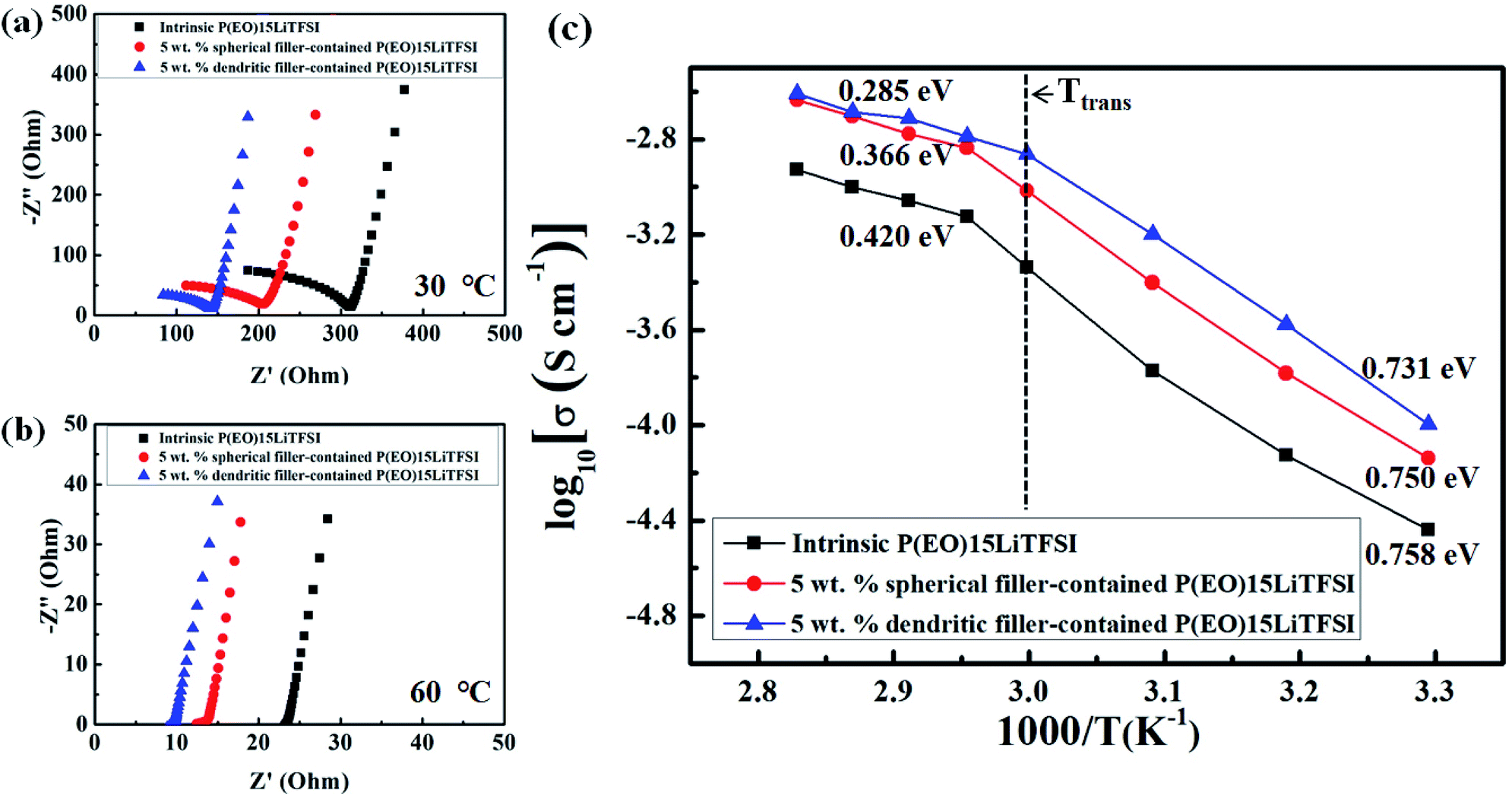 | ||
| Fig. 7 Nyquist plots obtained (a) at 30 °C and (b) 60 °C, and (c) temperature-dependent ion conductivity of the prepared SPEs. | ||
The Fig. 7c presents temperature dependency of the ionic conductivities of the prepared SPEs in this work. Overall, it shows that ionic conductivity (σ) of SPEs has been improved as temperature increases, following the Arrhenius-type activated process. As the temperature approaches up to phase-transition temperature (Ttrans) of PEO, the sharp increase in ionic conductivity of SPEs has been monitored, while the ionic conductivity increases slowly as the temperature goes over the Ttrans of PEO as interpreted by logσ vs. 1/T plots of Fig. 7c. The activation energy of temperature-dependent ionic conductivity is obtained according to Arrhenius-type behavior given in the following equation:41
 | (5) |
As shown in Fig. 8, the DC polarization curve has been also obtained using the cell of (stainless steel|5 wt% dendritic filler-contained P(EO)15LiTFSI|stainless steel) at 25 °C. The total ionic transference number (tion) of dendritic filler-contained P(EO)15LiTFSI was then evaluated by the eqn (2). The tion value was observed to be 0.99, which means that the ionic conductivity has been contributed by almost all the present ions in the polymer. To estimate the specific distribution of Li+ ion in LMPBs, the lithium-ion transference number (tLi+) in the filler-contained P(EO)15LiTFSI are also examined by the AC/DC polarization using the cell of (Li|filler-contained P(EO)15LiTFSI|Li) at 25 °C. The lithium-ion transference numbers (tLi+) were calculated by using the eqn (3). The tLi+ value was 0.29 and 0.38 for 5 wt% spherical filler-contained P(EO)15LiTFSI and 5 wt% dendritic filler-contained P(EO)15LiTFSI, respectively (cf. Fig. 9a and b), whereas the tLi+ value of intrinsic P(EO)15LiTFSI was only 0.17.58 The higher tLi+ value of the polymer provides the better electrochemical performance as the SPEs,59,60 which is explained by the increased ion mobility due to the Lewis acid–base effect. Furthermore, the value of tLi+ for dendritic filler-contained P(EO)15LiTFSI is higher than that of spherical filler-contained P(EO)15LiTFSI, which represents that dendritic filler-contained polymer presents better ion mobility in it. It is consistent with all the results of SEM, XRD, and DSC.
 | ||
| Fig. 8 Typical DC polarization curve for the cell of (stainless steel|5 wt% dendritic filler-contained P(EO)15LiTFSI|stainless steel) at 25 °C. | ||
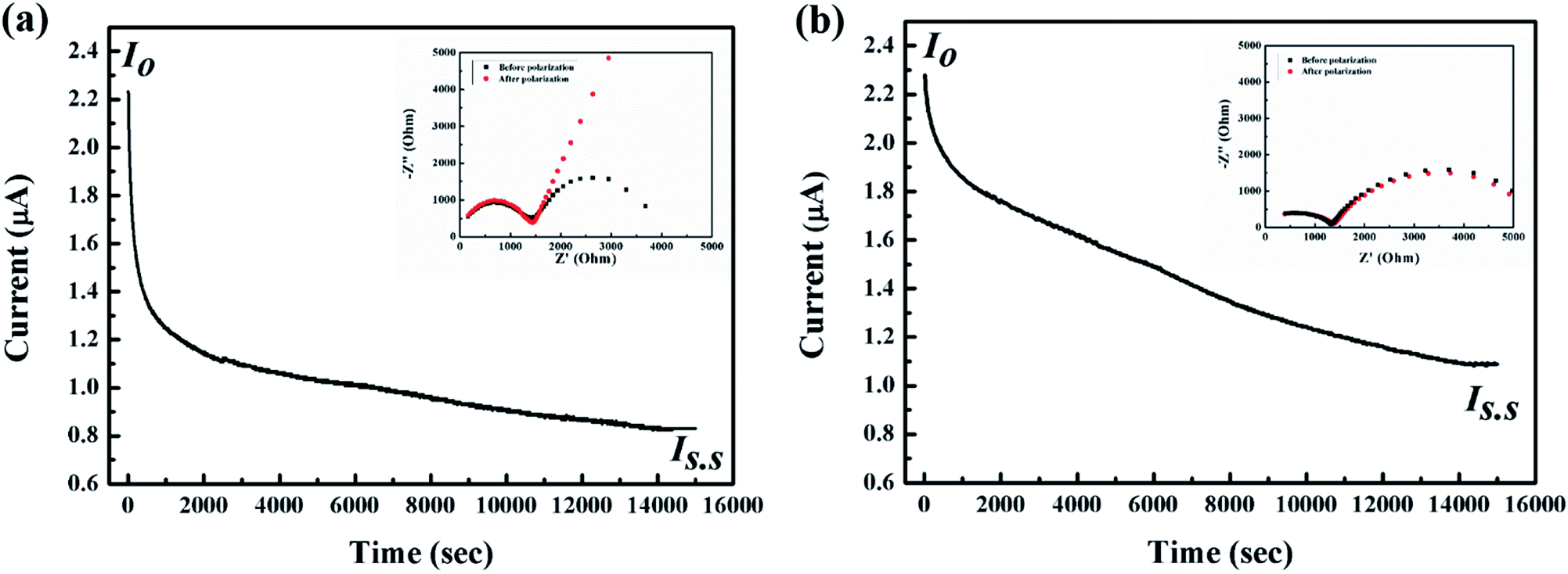 | ||
| Fig. 9 Typical DC polarization curves obtained from (a) 5 wt% spherical filler-contained P(EO)15LiTFSI and (b) 5 wt% dendritic filler-contained P(EO)15LiTFSI (inset shows Nyquist plots of AC polarization before and after DC polarization at 25 °C). | ||
3.5 LMPB cell performance
Fig. 10 shows the performance of the lithium symmetric cell at 25 °C with 5 wt% dendritic filler-contained P(EO)15LiTFSI polymer electrolyte. The half cycle of charging and discharging step was 2 hours, respectively. The cell potential was maintained stably during the repeated cycles of charging-discharging at a constant current density of 0.1 mA cm−2. | ||
| Fig. 10 Galvanostatic cycling performance of the Li symmetrical cells with 5 wt% dendritic filler-contained P(EO)15LiTFSI polymer electrolyte at a constant current density of 0.1 mA cm−2. Each half-cycle of charging and discharging step lasts 2 h at 25 °C. | ||
The cyclic performances are measured with the coin cell of (Li|5 wt% dendritic filler-contained P(EO)15LiTFSI|LiFePO4), in which the capacity evaluation of first cycle is excluded due to the usual SEI formation process. Fig. 11a presents the galvanostatic charge/discharge curves at various current rates (C-rates) at 25 °C. The specific discharge capacities of the cell were 51.03, 35.19, 20.19, 15.94, and 0.8 mA h g−1 at 0.1, 0.2, 0.3, 0.5, and 1 C-rate at 25 °C, respectively. The specific discharge capacities are observed to decrease with increase in C-rate as usual, which is caused by a large polarization.61 In general, the LMPBs with the SPEs based on PEO matrix hardly operate at 25 °C. However, the prepared LMPB with the dendritic filler-contained SPEs in this work has the discharge capacity of 51.03 mA h g−1 at 0.1 C-rate, because of its high ionic conductivity even at 25 °C.
 | ||
| Fig. 11 The galvanic charge–discharge profiles of (Li|LiFePO4) cell using 5 wt% dendritic filler-contained P(EO)15LiTFSI with various current rates at (a) 25 °C and (b) 60 °C, and the rate performance of (Li|LiFePO4) cell with intrinsic P(EO)15LiTFSI, 5 wt% spherical filler-contained P(EO)15LiTFSI, and 5 wt% dendritic filler-contained P(EO)15LiTFSI at (c) 25 °C and (d) 60 °C. | ||
As the cell operating temperature increases to 60 °C, the specific discharge capacity has improved drastically to 125, 113, 97, 78, and 52 mA h g−1 at 0.1, 0.2, 0.3, 0.5, and 1 C-rate, respectively (see Fig. 11b). These values of discharge capacities are suitable enough for LMPB application. This improvement is due to the crystallinity changes of PEO matrix in SPEs at different temperatures as discussed in DSC results (cf. Fig. 4).
For further evaluation on the effect of filler morphology in SPEs on the cell performance, the rate capabilities of the cells with intrinsic P(EO)15LiTFSI, 5 wt% spherical filler-contained P(EO)15LiTFSI, and 5 wt% dendritic filler-contained P(EO)15LiTFSI are compared at different temperatures. The specific capacities at various current rates (C-rates) at 25 °C are shown in Fig. 11c. When the intrinsic P(EO)15LiTFSI was used in the cell, the specific capacity was 7 mA h g−1 at 0.1 C-rate at 25 °C, which means that it is hardly operated at 25 °C. On the other hands, the SPEs with the fillers were operated reasonably at low current rates even at 25 °C. Moreover, the cell performance of the cell with the 5 wt% dendritic filler-contained P(EO)15LiTFSI is higher than that with 5 wt% spherical filler-contained P(EO)15LiTFSI. Furthermore, the specific capacities of the cell increase drastically at 60 °C, as shown in Fig. 11(d). The 5 wt% dendritic filler-contained P(EO)15LiTFSI also shows higher performance than the other solid polymer electrolytes, due to its superior ionic conductivity through the amorphous phase of PEO in the SPEs.
To elucidate the merits of solid polymer electrolytes, we have assembled the pouch cell of (Li|5 wt% dendritic filler-contained P(EO)15LiTFSI|LiFePO4) operating the light-emitting diode (LED) after it has been cut and folded as shown in Fig. 12. The cell still works properly and lights the light-emitting diode, which confirms safety and flexibility of the Li-metal polymer battery with the prepared solid polymer electrolyte in this work.
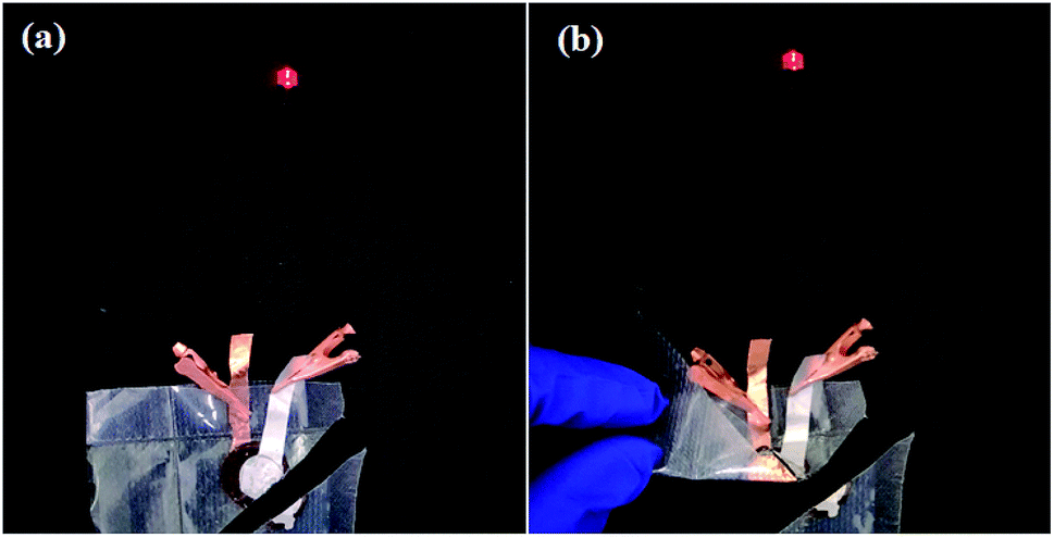 | ||
| Fig. 12 Photographs of the (Li|5 wt% dendritic filler-contained P(EO)15LiTFSI|LiFePO4) pouch cell operating the LED even (a) with being cut at corner and then (b) with being folded. | ||
4. Conclusions
The crystallinity of PEO matrix has been modified by adding the two different morphologies of copper-oxide fillers in the fabrication of solid polymer electrolytes (SPEs) for the application of lithium-metal polymer batteries (LMPBs). Both copper-oxide fillers of spherical and dendritic morphologies improve the ionic conductivity of the SPEs and their electrochemical performance, due to the generation of amorphous phase in the PEO matrix. The dendritic filler-contained SPE presents better electrochemical performance, of which surface interacts more with the PEO matrix and produces more amorphous phase. The ionic conductivity (σ) of the dendritic filler-contained P(EO)15LiTFSI is 1.007 × 10⁻⁴ S cm−1 and 1.368 × 10⁻³ S cm−1 at 30 °C and 60 °C, respectively. The dendritic filler-contained P(EO)15LiTFSI is thermally stable up to 300 °C and electrochemically stable up to 4.8 V. The (Li/LiFePO4) cell with the copper-oxide filler contained P(EO)15LiTFSI shows the enhanced discharge capacity of 125 mA h g−1 under 0.1 C-rate at 60 °C, whereas the cell is still operating even at 25 °C with 51.03 mA h g−1. In this work, the dendritic structure of copper-oxide fillers delivers better morphological effect on the enhancement of ionic conductivity by producing amorphous phase in the PEO matrix more than the spherical fillers. The safety and the flexibility of dendritic filler-contained SPEs in LMPBs application are also demonstrated.Conflicts of interest
There are no conflicts to declare.Acknowledgements
This research was supported by the Basic Science Research Program through the National Research Foundation of Korea (NRF) funded by the Ministry of Science, ICT, and Future Planning (NRF-2016R1A2A2A05005327), and the project for Cooperative R&D between Industry, Academy, and Research Institute funded Korea Ministry of SMEs and Startups in 2018 (S2605154). Also, the author acknowledges NRF for the financial support from the projects NRF-2016R1D1A1B03934561 and NRF-2019R1A2B5B01070383 funded by the Korea Government (MSIT).References
- M. Armand and J. M. Tarascon, Nature, 2008, 451, 652–657 CrossRef CAS.
- V. Etacheri, R. Marom, R. Elazari, G. Salitra and D. Aurbach, Energy Environ. Sci., 2011, 4, 3243–3262 RSC.
- E. Quartarone and P. Mustarelli, Chem. Soc. Rev., 2011, 40, 2525–2540 RSC.
- H. S. Ko, H. W. Park, G. J. Kim and J. D. Lee, Korean J. Chem. Eng., 2019, 36, 620–624 CrossRef CAS.
- J. Lee and J. H. Moon, Korean J. Chem. Eng., 2017, 34, 3195–3199 CrossRef CAS.
- J. Janek and W. G. Zeier, Nat. Energy, 2016, 1, 1–4 Search PubMed.
- A. L. Robinson and J. Janek, MRS Bull., 2014, 39, 1046–1047 CrossRef.
- M. Wakihara, Y. Kadoma, N. Kumagai, H. Mita, R. Araki, K. Ozawa and Y. Ozawa, J. Solid State Electrochem., 2012, 16, 847–855 CrossRef CAS.
- P. G. Balakrishnan, R. Ramesh and T. Prem Kumar, J. Power Sources, 2006, 155, 401–414 CrossRef CAS.
- Y. Zhao, Z. Huang, S. Chen, B. Chen, J. Yang, Q. Zhang, F. Ding, Y. Chen and X. Xu, Solid State Ionics, 2016, 295, 65–71 CrossRef CAS.
- Y. Zhao, C. Wu, G. Peng, X. Chen, X. Yao, Y. Bai, F. Wu, S. Chen and X. Xu, J. Power Sources, 2016, 301, 47–53 CrossRef CAS.
- B. Chen, Z. Huang, X. Chen, Y. Zhao, Q. Xu, P. Long, S. Chen and X. Xu, Electrochim. Acta, 2016, 210, 905–914 CrossRef CAS.
- S. Ahmad, Ionics, 2009, 15, 309–321 CrossRef CAS.
- Z. Zhang and S. Fang, Electrochim. Acta, 2000, 45, 2131–2138 CrossRef CAS.
- J. W. Fergus, J. Power Sources, 2010, 195, 4554–4569 CrossRef CAS.
- A. Mauger, M. Armand, C. M. Julien and K. Zaghib, J. Power Sources, 2017, 353, 333–342 CrossRef CAS.
- L. Yue, J. Ma, J. Zhang, J. Zhao, S. Dong, Z. Liu, G. Cui and L. Chen, Energy Storage Materials, 2016, 5, 139–164 CrossRef.
- J. Y. Song, Y. Y. Wang and C. C. Wan, J. Power Sources, 1999, 77, 183–197 CrossRef CAS.
- S. Rajendran, Solid State Ionics, 2004, 167, 335–339 CrossRef CAS.
- B. Sun, J. Mindemark, K. Edström and D. Brandell, Solid State Ionics, 2014, 262, 738–742 CrossRef CAS.
- F. R. Wang, L. B. Li, X. Y. Yang, J. You, Y. P. Xu, H. Wang, Y. Ma and G. X. Gao, Sustainable Energy Fuels, 2018, 2, 492–498 RSC.
- Z. G. Xue, D. He and X. L. Xie, J. Mater. Chem. A, 2015, 3, 19218–19253 RSC.
- L. Porcarelli, C. Gerbaldi, F. Bella and J. R. Nair, Sci. Rep., 2016, 6, 19892 CrossRef CAS.
- D. Golodnitsky, E. Strauss, E. Peled and S. Greenbaum, J. Electrochem. Soc., 2015, 162, A2551–A2566 CrossRef CAS.
- A. Manuel Stephan, Eur. Polym. J., 2006, 42, 21–42 CrossRef CAS.
- P. Johansson, Polymer, 2001, 42, 4367–4373 CrossRef CAS.
- R. Tanaka, M. Sakurai, H. Sekiguchi, H. Mori, T. Murayama and T. Ooyama, Electrochim. Acta, 2001, 46, 1709–1715 CrossRef CAS.
- S. K. Fullerton-Shirey and J. K. Maranas, Macromolecules, 2009, 42, 2142–2156 CrossRef CAS.
- Y. Li, Y. Zhao, Y. Cui, Z. Zou, D. Wang and S. Shi, Comput. Mater. Sci., 2018, 144, 338–344 CrossRef CAS.
- L. Meabe, T. V. Huynh, N. Lago, H. Sardon, C. Li, L. A. O'Dell, M. Armand, M. Forsyth and D. Mecerreyes, Electrochim. Acta, 2018, 264, 367–375 CrossRef CAS.
- C. Wang, Q. Sun, Y. Liu, Y. Zhao, X. Li, X. Lin, M. N. Banis, M. Li, W. Li, K. R. Adair, D. Wang, J. Liang, R. Li, L. Zhang, R. Yang, S. Lu and X. Sun, Nano Energy, 2018, 48, 35–43 CrossRef CAS.
- B. W. Zewde, L. Carbone, S. Greenbaum and J. Hassoun, Solid State Ionics, 2018, 317, 97–102 CrossRef CAS.
- S. K. Singh, Shalu, L. Balo, H. Gupta, V. K. Singh, A. K. Tripathi, Y. L. Verma and R. K. Singh, Energy, 2018, 150, 890–900 CrossRef CAS.
- L. Wang, X. Li and W. Yang, Electrochim. Acta, 2010, 55, 1895–1899 CrossRef CAS.
- C. He, J. Liu, J. Cui, J. Li and X. Wu, Solid State Ionics, 2018, 315, 102–110 CrossRef CAS.
- S. Farheen and R. D. Mathad, Mater. Today: Proc., 2016, 3, 3632–3636 Search PubMed.
- K. Vignarooban, M. A. K. L. Dissanayake, I. Albinsson and B. E. Mellander, Solid State Ionics, 2014, 266, 25–28 CrossRef CAS.
- S. Klongkan and J. Pumchusak, Electrochim. Acta, 2015, 161, 171–176 CrossRef CAS.
- S. Chen, J. Wang, Z. Zhang, L. Wu, L. Yao, Z. Wei, Y. Deng, D. Xie, X. Yao and X. Xu, J. Power Sources, 2018, 387, 72–80 CrossRef CAS.
- F. Croce, G. B. Appetecchi and L. Persi, Nature, 1998, 394, 456–458 CrossRef CAS.
- S. K. Chaurasia and A. Chandra, Solid State Ionics, 2017, 307, 35–43 CrossRef CAS.
- Z. H. Zhang, Y. R. Zhao, S. J. Chen, D. J. Xie, X. Y. Yao, P. Cui and X. X. Xu, J. Mater. Chem. A, 2017, 5, 16984–16993 RSC.
- X. T. Fu, D. N. Yu, J. W. Zhou, S. W. Li, X. Gao, Y. Z. Han, P. F. Qi, X. Feng and B. Wang, CrystEngComm, 2016, 18, 4236–4258 RSC.
- R. Liu, P. He, Z. Wu, F. Guo, B. Huang, Q. Wang, Z. Huang, C.-a. Wang and Y. Li, J. Electroanal. Chem., 2018, 822, 105–111 CrossRef CAS.
- A. Enotiadis, N. J. Fernandes, N. A. Becerra, M. Zammarano and E. P. Giannelis, Electrochim. Acta, 2018, 269, 76–82 CrossRef CAS.
- D. Zhou, R. Liu, Y.-B. He, F. Li, M. Liu, B. Li, Q.-H. Yang, Q. Cai and F. Kang, Adv. Energy Mater., 2016, 6 Search PubMed.
- Y.-S. Park, C. Y. An, P. K. Kannan, N. Seo, K. Zhuo, T. K. Yoo and C.-H. Chung, Appl. Surf. Sci., 2016, 389, 865–873 CrossRef CAS.
- S. K. Chaurasia and R. K. Singh, Phase Transitions, 2010, 83, 457–466 CrossRef CAS.
- M. Watanabe, M. Kanba, K. Nagaoka and I. Shinohara, J. Polym. Sci., Polym. Phys. Ed., 1983, 21, 939–948 CrossRef CAS.
- J. Evans, C. A. Vincent and P. G. Bruce, Polymer, 1987, 28, 2324–2328 CrossRef CAS.
- W. Li, Y. Pang, J. Liu, G. Liu, Y. Wang and Y. Xia, RSC Adv., 2017, 7, 23494–23501 RSC.
- K. Zhuo, C. Y. An, P. K. Kannan, N. Seo, Y.-S. Park and C.-H. Chung, Korean J. Chem. Eng., 2017, 34, 1483–1489 CrossRef CAS.
- H. Gupta, Shalu, L. Balo, V. K. Singh, S. K. Chaurasia and R. K. Singh, RSC Adv., 2016, 6, 87878–87887 RSC.
- M. Chintapalli, X. C. Chen, J. L. Thelen, A. A. Teran, X. Wang, B. A. Garetz and N. P. Balsara, Macromolecules, 2014, 47, 5424–5431 CrossRef CAS.
- S. R. Mohapatra, A. K. Thakur and R. N. P. Choudhary, J. Power Sources, 2009, 191, 601–613 CrossRef CAS.
- J. H. Shin, K. W. Kim, H. J. Ahn and J. H. Ahn, Mater. Sci. Eng., B, 2002, 95, 148–156 CrossRef.
- H. Gupta, Shalu, L. Balo, V. K. Singh, S. K. Singh, A. K. Tripathi, Y. L. Verma and R. K. Singh, Solid State Ionics, 2017, 309, 192–199 CrossRef CAS.
- X. Judez, M. Piszcz, E. Coya, C. Li, I. Aldalur, U. Oteo, Y. Zhang, W. Zhang, L. M. Rodriguez-Martinez, H. Zhang and M. Armand, Solid State Ionics, 2018, 318, 95–101 CrossRef CAS.
- B. Jinisha, K. M. Anilkumar, M. Manoj, V. S. Pradeep and S. Jayalekshmi, Electrochim. Acta, 2017, 235, 210–222 CrossRef CAS.
- J. F. Vélez, M. Aparicio and J. Mosa, Electrochim. Acta, 2016, 213, 831–841 CrossRef.
- I. Aldalur, M. Martinez-Ibañez, M. Piszcz, L. M. Rodriguez-Martinez, H. Zhang and M. Armand, J. Power Sources, 2018, 383, 144–149 CrossRef CAS.
Footnote |
| † These authors contributed equally to this work. |
| This journal is © The Royal Society of Chemistry 2019 |